

Page 1
User’s Guide
400A AC/DC Clamp Meter
Model MA220
Page 2

MA220-EU-EN V1.5 7/09
2
Introduction
Thank you for selecting the Extech MA220 AC/DC Clamp Meter. This meter measures
AC/DC Current, AC/DC Voltage, Resistance, Capacitance, Frequency, Duty Cycle,
Temperature, Diode Test, and Continuity. This professional meter, with proper care, will
provide years ofsafe reliable service.
Safety
International Safety Symbols
This symbol, adjacentto another symbol or terminal,indicates the user must
refer to the manual for further information.
This symbol, adjacentto a terminal, indicates that, undernormal use,
hazardous voltages may be present
Double insulation
SAFETY NOTES
Do not exceed the maximum allowableinput range of any function
Do not apply voltage tometer when resistance function is selected.
Set the function switch OFF whenthe meter isnot in use.
Remove the battery if meter isto be stored for longer than 60 days.
WARNINGS
Set function switch to the appropriateposition before measuring.
When measuring volts do not switch to current/resistancemodes.
Do not measure current ona circuit whosevoltage exceeds 240V.
When changing ranges using the selectorswitch always disconnect the test leads
from the circuit under test.
Do not exceed the maximum ratedinput limits.
OVERVOLTAGE CATEGORY III
This meter meets the IEC 610-1-95 standard for OVERVOLTAGE CATEGORY III. Cat III
meters are protectedagainst overvoltage transients in fixed installation at the distribution
level. Examples include switches in thefixed installation andsome equipment for industrial
use with permanentconnection to the fixed installation.
Page 3
MA220-EU-EN V1.5 7/09
3
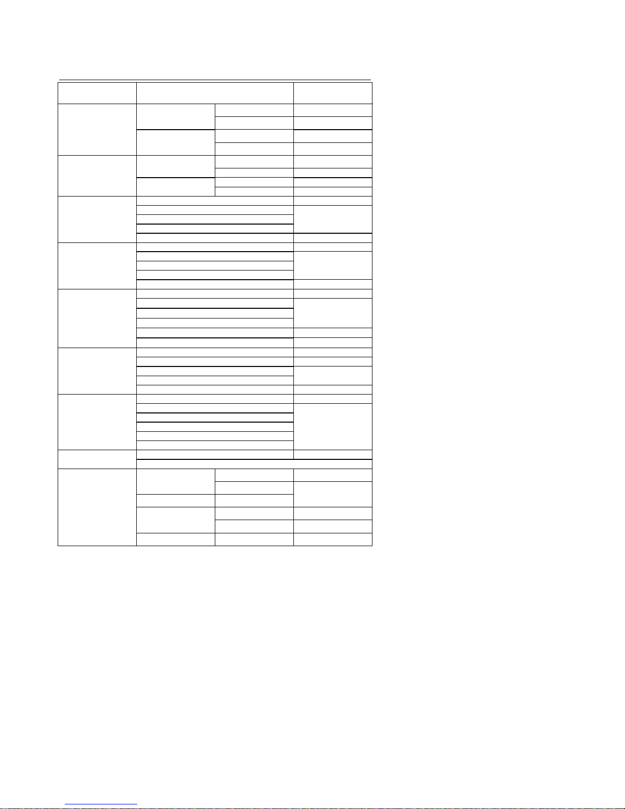
Specifications
Function
Range
Accuracy (of
reading)
DC Current 40.00 ADC
0-20.00 ADC ± (2.5% + 6 digits)
20.00-40.00 ADC ± (3% + 6 digits)
400.0 ADC
0-300.0 ADC ± (2.5% + 6 digits)
300.0-400.0 ADC ± (3.5% + 6 digits)
AC Current 40.00 AAC
0-20.00 AAC ± (3% + 10 digits)
20.00-40.00 AAC ± (5% + 10 digits)
400.0 AAC 0-300.0 AAC ± (3% + 10 digits)
300.0-400.0 AAC ± (5% + 10 digits)
DC Voltage
400.0mV± (0.8% + 3
digits)4.000V
± (1.5% + 3 digits)40.00V
400.0V
600V ± (2.0% + 3 digits)
AC Voltage 400.0mV ± (1% + 10 digits)
4.000V
± (2% + 5 digits)40.00V
400.0V
600V ± (2% + 5 digits)
Resistance
400.0
± (1.0% + 4 digits)
4.000k
± (1.5% + 2 digits)
40.00k
400.0
k
4.000 M
± (2.5% + 3 digits)
40.00M
± (3.5% + 5 digits)
Capacitance 40.00nF ± (5% + 30 digits)
400.0nF ± (3% + 5 digits)
4.000µF ± (3.5% + 5 digits)
40.00µF
100.0µF ± (5% + 5 digits)
Frequency
5.000Hz
± (1.5% + 5
digits)
50.00Hz
± (1.2% + 2 digits)
Sensitivity: 5~5KHz:
10Vrms min.
5KHz~150KHz:
40Vrms min.
500.0Hz
5.000KHz
50.00KHz
150.0KHz
Duty Cycle 0.5% to 99.0% ± (1.2% + 2 digits)
Pulse Width: 100µs-100ms,Frequency: 5Hz to 150KHz
Temperature -50.0 to 400.0°C
-50.0 to -20.0°C ± 7°C
-20.0 to 400.0°C
± (3% + 5 °C)
400 to 1000°C
400 to 1000°C
-58.0 to 400.0°F
-58.0 to 0°F ± 14°F
0 to 400.0°F ± (2.5% + 6 digits)
400 to 1832°F
400 to 1832°F ± (3% + 7°F)
Page 4

MA220-EU-EN V1.5 7/09
4
Jaw size 23mm (0.9") approx.
Display 4000 count LCD
Continuity Audible tone < 150 approx.
Diode Test Open circuit voltage < 1.5VDC;
Test current 0.3mA(typical)
AC V bandwidth 50Hz to 400Hz
AC A bandwidth 50/60Hz
Low battery indication “ ” is displayed
Overrange indication “OL” is displayed
Auto Power OFF After 30 minutes
Measurement rate 2 per second, nominal
Input Impedance 7.8MΩ (V DC and V AC)
Operating Temperature 5ºC to 40ºC(41ºF to 104ºF)
Storage Temperature -20oC to 60oC (-4oF to 140oF)
Operating Humidity Max 80% up to 31ºC (87ºF) decreasing linearly to 50% at 45ºC
(113ºF)
Storage Humidity <80%
Operating Altitude 2000meters (6560ft.) operating
Batteries (2) 1.5V AAA batteries
Weight 200g (0.44lb)
Size 200x50x35mm (7.87” x1.97” x 1.38”)
Safety For indoor use and in accordance with the requirements for
double insulation to IEC1010-1 (1995):EN61010-1 (1995)
Overvoltage Category III, Pollution Degree 2.
Page 5

MA220-EU-EN V1.5 7/09
5
Meter Description
1. Conductor jaws
2. Jaw opening trigger
3. Function select switch
4. LCD Display
5. ZERO button
6. Data Hold andBacklight Button
7. Mode select button
8. Range select button
9. Hz/%/Duty Cycle button
10. COM input jack
11. V/Temp jack
12. Battery cover (rear)
AC AC(alternating current)
DC DC(direct currrent)
Minus sign
AUTO AutoRange mode
ZERO ZERO mode
•))) Audible Continuity
HOLD Data Hold mode
Low Battery icon
Diode test mode
m milli
V Volts
A Amps
K kilo
M Mega
Ω Ohms
°F Degrees Fahrenheit
°C Degrees Centigrade
Page 6

MA220-EU-EN V1.5 7/09
6
Operation
Notice: Read andunderstand all WARNING and CAUTION statementslisted in the
safety section of this operation manual prior to using this meter. Set the function select
switch to the OFF position when the meter is not in use.
DC/AC Current Measurements
Warning: Disconnect the test leads from the meter before making
current clamp measurements.
1. Set the Functionswitch to the 400ADC, 40ADC, 400AAC or
40AAC range. If the range of the measured is not known, select
the higher range first then move to the lower range if necessary.
2. For DC current measurement, press theZERO key to null the
meter display.
3. Press the trigger to open jaw. Fully enclose one conductor to be
measured.
4. The clamp meter LCD will display the reading.
DC/AC Voltage Measurements
1. Set the rotary function switch to the Volts/Hz/%position.
2. Insert the black test lead banana plug into the negative(COM) jack and the red test lead
banana plug intothe positive (V/Temp) jack
3. Select AC or DC withthe MODE button
4. Connect the test leads to the circuit under test
5. Read the voltage on thedisplay. The displaywill indicate theproper decimal pointand
value.
Resistance Measurements
1. Set the function switch to the •))) CAP position.
2. Insert the black test lead banana plug into the negative(COM) jack
Insert the red test lead banana plug into the positive (V Temp jack.
3. Touch the test probe tips across the circuit or part under test. It is best to disconnect one
side of thepart under test so the rest of the circuit will not interfere with the resistance
reading.
4. Read the resistance on the display. The display will indicatethe proper decimal point and
value.
Continuity Check
1. Set the function switch to the •))) CAP position.
2. Push the mode button to indicate •))) on the display.
3. Insert the black lead banana plug into thenegative (COM) jack
Insert the red test lead banana plug into the positive (V) jack.
4. Touch the test probe tips to the circuitor wire you wish to check.
5. If the resistance is less than approximately 150, the audible signal will sound. If the
circuit is open, the display will indicate “OL.”.
Page 7

MA220-EU-EN V1.5 7/09
7
Diode Test
1. Turn the rotary switch to the •))) CAP position.
2. Insert the black test lead banana plug into the negative(COM) jack and the red test lead
banana plug intothe positive (V jack.
3. Push the mode button to indicate on the display.
4. Touch the test probes to the diode under test. Typically for a normal diode, forward
voltage will indicate0.4V to 0.7V. Reverse voltage will indicate “OL”. Shorted devices will
indicate near 0Vand an open device will indicate “OL” in both polarities.
Capacitance Measurements
Warning: To avoid electrical shock,disconnect power to the unit under test and
discharge all capacitorsbefore taking any capacitance measurements. Remove the
batteries and unplug the line cords.
1. Set the function switch to the •))) CAP position.
2. Push the mode buttonto indicate nF on the display.
3. Insert the black lead banana plug into the negative(COM) jack and
insert the red test lead banana plug into the positive (VTemp) jack.
4. Press the ZERO key to null the meter display.
5. Touch the test probe tips to thecapacitor you wish to check.
6. Read the capacitance value on the display.
Frequency or % Duty Cycle Measurements
1. Turn the rotary switch to the Volts Hz % position.
2. Insert the black test lead banana plug into the negative(COM) jack and the red test lead
banana plug intothe positive (V jack.
3. Select Hz or % with the HZ/% button.
4. Touch the test probe tips to thecircuit under test.
5. Read the frequency on the display.
Temperature Measurements
1. Turn the rotary switch to the Temp position.
2. Insert the Temperature Probe into the negative (COM) and the (VTemp jacks, making
sure to observe correct polarity.
3. Select °C or °F with the MODE button.
4. Touch the temperature probe head to the part whose temperature you wish to measure.
Keep the probe touching the part under test until the reading stabilizes.
5. Read the temperature on the display.
Warning: To avoid electrical shock,be sure the thermocouple has been removed before
changing to another measurement function.
Auto/Manual Ranging
The meter turns on in Autoranging mode. Press the RANGE button to enter manual
ranging. Each press of the range button will step to the next range as indicated by theunits
and decimal point location. Press and hold the RANGE button for two seconds to return to
Autoranging mode.
Note: Manual ranging does not function in AC Current or Diode and Continuity check
functions. In Temperature function, itwill change theresolution from 0.1° to 1°.
Page 8

MA220-EU-EN V1.5 7/09
8
Data Hold
To freeze theLCD meter reading, press the HOLD button. While data hold is active, the
HOLD display iconappears on the LCD. Press the HOLD button again to return to normal
operation.
Backlight
Press and hold the HOLD button for >2 seconds to turn the backlight on/off.
Note: The HOLD feature will activatewhen the backlight is turned on. Press the HOLD
button again to exit the Hold feature.
Zero Button
Zeros Capacitance and DC Current measurements. Also allows the user to offset the
meter by using the displayed value as the zero reference value. Press the
ZERO
key
momentarily to activate and to exit Zero mode.
Maintenance
WARNING: To avoid electrical shock, disconnect themeter from anycircuit, remove the
test leads from the input terminals and turn OFF the meter before opening the case. Do
not operate withopen case.
Cleaning and Storage
Periodically wipe the case with adamp cloth andmild detergent; do not use abrasives or
solvents. If themeter is not to be used for periodsof longer than60 days, remove the
batteries and store them separately
Battery Replacement
1. Remove the two rear Phillips head screws
2. Open the battery compartment
3. Replace the two 1.5V AAAbatteries.
4. Re-assemble the meter
You, as the end user, are legally bound (Battery ordinance) to return all used
batteries and accumulators; disposal in the household garbage is prohibited!
You can hand over your used batteries / accumulators at collection points in
your community or wherever batteries /accumulators are sold!
Disposal:
Follow the valid legal stipulations in respect of the disposal of the
device at the end of its lifecycle
Copyright © 2004 Extech Instruments Corporation.
All rights reserved including the right of reproduction in whole or in part in any form.
 Loading...