

Page 1

White LED Light Meter
Model LT40
Additional User Manual Translations available at www.extech.com
USER MANUAL
www.GlobalTestSupply.com
Page 2

2
Introduction
Congratulations on your purchase of the Extech LT40 LED Light Meter that measures light from
white LED light, fluorescent, metal halide, high-pressure sodium and incandescent sources. The
LT40 can measure light up to 400,000 Lux (40,000 Fc). The LT40 offers an overload indication, low
battery indication, Data hold, maximum/average/minimum hold (MAX/MIN), Zero adjustment,
auto power off with disable function, and auto ranging features. This instrument is shipped fully
tested and calibrated and, with proper use, will provide years of reliable service. Please visit our
website (www.extech.com) to check for the latest version of this User Guide, Product Updates, and
Customer Support.
Features
• Overload Indication: LCD screen will show “OL” at the upper left-hand corner.
• Low battery Indication”
• Display Update Rate: 2.5 times per second.
• Spectral response near CIE luminous spectral efficiency ratings.
• Cosine Angle corrected.
• Conforms to JIS C 1609:1993 and CNS 5119 general class A Specifications.
• Measures LED white light and all visible light.
• Measures the intensity of illumination in Lux or foot-candles.
• Applications include: Warehouses, factories, office buildings, restaurants, schools, library,
hospitals, photo/video, parking garages, museums, art galleries, stadiums, building
security.
• Data hold freezes displayed reading.
• Maximum/Average/Minimum Memory Hold
• Zero adjustment.
• Auto power off with disable function.
• Auto range.
”.
Safety
• Do not operate the meter in environments where the following are present: explosive gases
(or materials), combustible gases (or materials), steam, or dust.
• Please replace the battery immediately when the symbol “ ” appears on the LCD.
• Do not touch the meter’s circuit board for any reason as static electricity or contamination
could damage the sensitive components.
• For Indoor use only. This instrument was designed for pollution degree 2.
• Operation Altitude: Up to 2000m (7000’).
www.GlobalTestSupply.com
LT40-en-GB_V2.2 2/17
Page 3
3
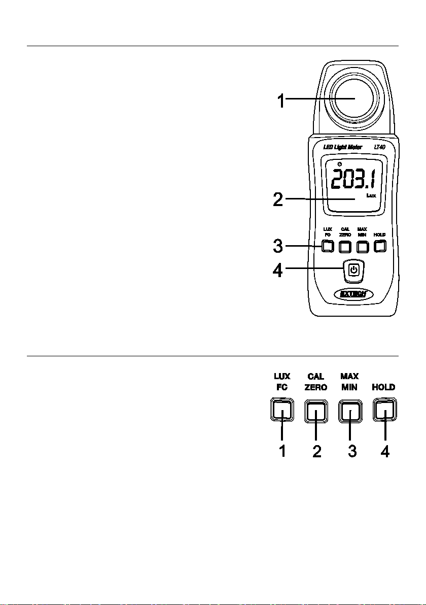
Meter Description
1. Photo detector (remove protective cover to expose sensor)
2. Display (LCD)
3. Control push-buttons
4. Power Button: ON/OFF
Battery compartment and tripod mount are located on
rear of instrument
Push-Button Description
1. Lux/Fc units selector
2. Calibration and ZERO button
3. Maximum/Average/Minimum memory button
4. Data hold button
LT40-en-GB_V2.2 2/17
www.GlobalTestSupply.com
Page 4

4
Operation
Power ON-OFF
Press and hold the Power button for at least 2 seconds and then release to power the meter. To
power the meter OFF, momentarily press the Power button.
Taking Measurements
1. Switch the meter ON and remove the sensor’s protective cover to expose the light sensor
dome. The display should switch ON, if not check that batteries are installed and fresh.
2. The meter measures the intensity of the light (illuminance) that strikes the sensor dome in
foot candles and lux units (1 fc = 10.76 lux), displaying this measured value on its LCD.
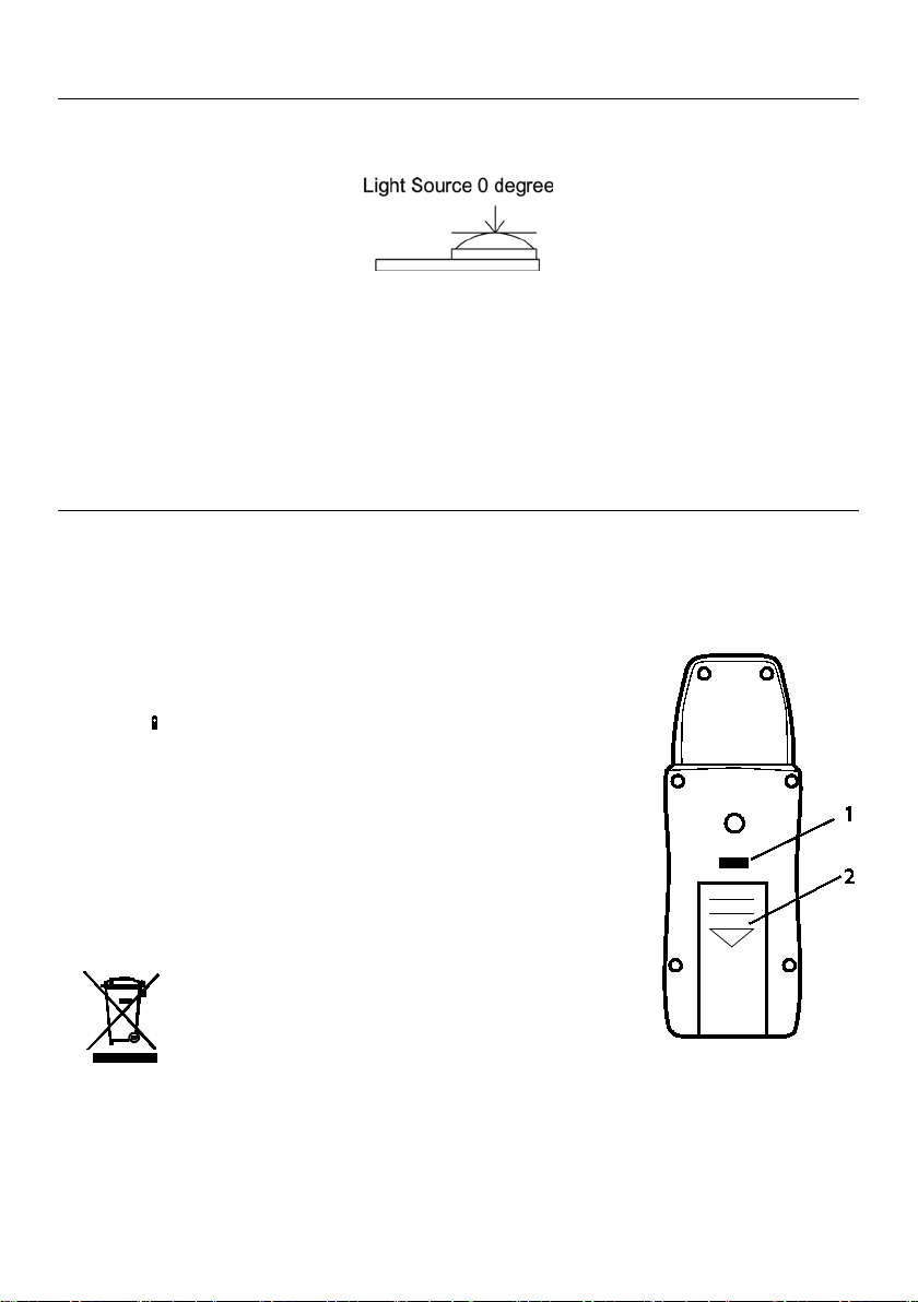
3. Position the meter and light source so that the light strikes the sensor dome straight on
(perpendicular) with as little an angle as possible.
4. The meter’s display can show a value up to 3999. However, for readings that represent
measurements higher than this, the meter uses x10 feature (right-most decimal point
flashing). For example, to represent a measurement of 39,990 the meter will display 3999
with the right-most digit flashing.
Auto Power OFF
To save battery life, the meter powers down automatically after approximately 12 minutes of
inactivity.
Enable/Disable Auto Power Off
While the meter is ON, press and hold the Power button for at least 2 seconds (and then release)
to disable the Auto Power OFF utility; the Clock symbol will switch OFF. To enable the Auto
Power OFF utility, repeat this process.
LUX/FC Button
Press the LUX/FC button to toggle between Lux and FC (foot-candles) measurement units.
LT40-en-GB_V2.2 2/17
www.GlobalTestSupply.com
Page 5

5
MAX/MIN Button
The meter can record the maximum, minimum, and average readings as described below:
1. Short press the “MAX/MIN” button and the meter will begin to track the
maximum/average/minimum measurements; the “MAX” icon will display at the top of the
LCD window indicating that the meter is now showing the maximum reading. The reading
will not change until a higher reading is registered.
2. Press the “MAX/MIN” button again to switch from “MAX” to “AVG”, where the meter will
show the average measurement value. The “AVG” icon will be displayed above the displayed
value.
3. Press the “MAX/MIN” button again to change the mode from “AVG” to “MIN”, where the
meter will show the minimum value measured. The “MIN” icon will be displayed.
4. Press the “MAX/MIN” button again to switch from “MIN” back to “MAX”.
5. To exit this mode, hold the “MAX/MIN” button for at least 2 seconds. The MAX/AVG/MIN
icons should all be switched OFF when the unit returns to the normal operating mode.
Data ‘Hold’ Button
Press the HOLD button to freezes the current reading on the LCD. Press the HOLD button again
to release the reading.
www.GlobalTestSupply.com
LT40-en-GB_V2.2 2/17
Page 6

6
CALIBRATION and ZERO Buttons
1000 LUX Calibration
WARNING: The 1000 LUX calibration should be performed by qualified personnel only, equipped with the
exact light source specified in the instructions. Performing a 1000 LUX calibration without a proper light
source or without following the specific steps correctly will lead to the clearing of the stored calibration
data, rendering the unit unusable. If the calibration data is inadvertently cleared it cannot be recreated
until a proper calibration is performed.
1. Prepare a 2856
toward the light source.
2. Power ON the meter.
3. Simultaneously press and hold the “CAL/ZERO” button and the power button for at least
2 seconds.
4. Release the buttons when “CAL” is displayed on the LCD screen.
5. Place the LT40 in the light source. Press and hold the “CAL” button for 2 more seconds,
and the LT40 will power down.
6. The meter is now calibrated.
ZERO Calibration
1. Ensure that the protective cover is attached to the light sensor.
2. Power the meter and the LCD should display ‘0’.
3. Momenarily press the “ZERO” button for the zero adjustment and the CAL icon will
switch ON.
4. The CAL icon will switch OFF when the calibration has been completed.
5. If the protective cap is not covering the sensor when the ZERO calibration is started the
LCD display will read “CAP”. In this case, please cover the sensor with the cap and restart
this procedure.
o
K/1000 Lux light source and face the meter’s sensor perpendicularly
www.GlobalTestSupply.com
LT40-en-GB_V2.2 2/17
Page 7
7
Measurement Considerations and User Tips
• For maximum accuracy allow the light being measured to fall directly on the sensor as
perpendicular as possible with a minimal angle of incidence.
• When the meter is not in use please keep the protective cap in place over the light sensor.
This will prolong the life of the sensor.
• When the meter is to be stored for long periods, please remove the batteries and store them
separately. Batteries can leak and cause damage to the meter’s components.
• Avoid areas of high temperature and humidity when using this instrument.
Battery Replacement and Maintenance
Cleaning and storage
1. The white plastic sensor dome should be cleaned with a damp cloth when necessary. Use
only a mild soap if needed. Do not use solvents, abrasives, or harsh detergents to clean the
dome.
2. Store the meter in an area with moderate temperature and relative humidity.
Battery Replacement
When the battery power decreases to a critical level, the low battery
symbol “ ”will appear on the LCD. Replace the 2 x 1.5V AAA batteries
located in the rear battery compartment.
1. Press and hold the battery compartment lock button (see
diagram).
2. Slide the battery compartment cover off in the direction of the
arrow.
Install two (2) 1.5V ‘AAA’ batteries observing polarity and close the
battery compartment. Ensure that the compartment cover is securely
fastened before using the meter.
Never dispose of used batteries or rechargeable batteries
in household waste.
As consumers, users are legally required to take used
batteries to appropriate collection sites, the retail store where the batteries were
purchased, or wherever batteries are sold.
Disposal: Do not dispose of this instrument in household waste. The user is obligated to take
end-of-life devices to a designated collection point for the disposal of electrical and electronic
equipment.
www.GlobalTestSupply.com
LT40-en-GB_V2.2 2/17
Page 8
8
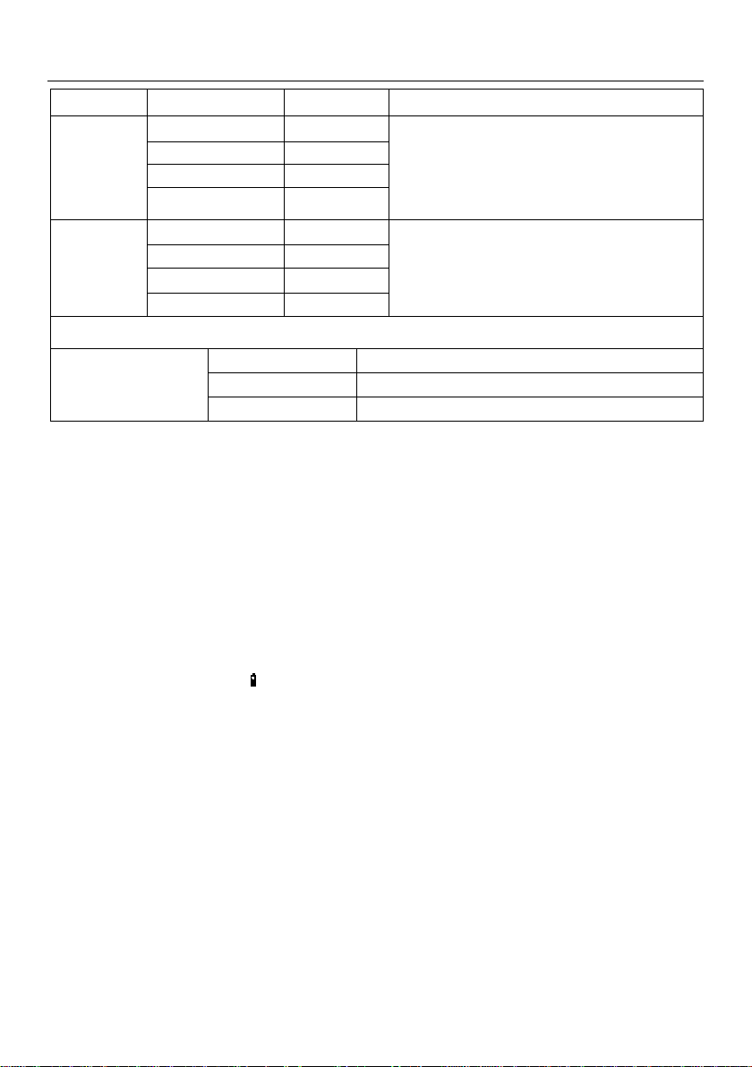
Specifications
3999
1
Units Range Resolution Accuracy
Lux
Foot
candles
Angle deviation from
cosine characteristics
399.9 0.1
39,990* 10
399,900* 100
39.99 0.01
399.9 0.1
3999 1
39,990* 10
* Readings above 3999 use a x10 or x100 multiplier (1 Fc = 10.76 Lux)
30° ±2%
60° ±6%
80° ±25%
General Specifications
Sampling rate 2.5 times per second (digital display)
Photo detector Silicon photo-diode with spectral response filter and cosine
correction
Display 4-digit LCD (maximum display: 3999) with low battery icon,
measurement overload, and other function indicators
Auto Range The meter automatically ranges the display
Operating conditions Temperature: 5 to 40
Storage conditions Temperature: -10 to 60
Low battery indication “
LED Type White LED light can be accurately measured
Power supply 2 x 1.5V ‘AAA’ batteries
Battery life Approximately 200 hours
Auto Power OFF Meter switches OFF after 12 minutes of inactivity
Dimensions 133 x 48 x 23 mm (5.2 x 1.9 x 0.9”)
Weight 250 g. (8.8 oz.) including batteries
” appears on the LCD when battery voltage falls critically low
LED: ±(3%reading + 3 Lux) up to 500 Lux
±(3%reading) >500 Lux
Visible: ±(8%reading + 3 Lux)
LED: ±(3%reading + 0.3 Fc) up to 46 Fc
±(3%reading) >46 Fc
Visible: ±(8%reading + 0.3 Fc)
o
C (41 to 104oF); Humidity: < 80% RH
o
C (14 to 140oF); Humidity: < 70% RH
www.GlobalTestSupply.com
LT40-en-GB_V2.2 2/17
Page 9

9
Appendices
Lux
Foot
Candles
Lux
Foot
Candles
Factories
Home
20-75
2-7
Emergency Stairs, Warehouse
100-150
10-15
Washing
75-150
7-15
Exit/Entrance Passages
150-200
15-20
Recreational
Activities
150-300
15-30
Packing Work
200-300
20-30
Drawing Room,
Table
300-750
30-75
Visual Work: Production Line
300-500
30-50
Makeup
750-1,500
75-150
Typesetting: Inspection Work
500-1,500
50-150
Reading, Study
1,500-3,000
150-300
Electronic Assembly, Drafting
1,000-2,000
100-200
Sewing
Office
Restaurant
75-100
7-10
Indoor Emergency Stairs
75-150
7-15
Corridor Stairs
100-200
10-20
Corridor Stairs
150-300
15-30
Entrance,
Wash Room
200-750
20-75
Conference,
Reception Room
300-750
30-75
Cooking Room,
Dining Table
750-1,500
75-150
Clerical Work
750-1,500
75-150
Show Window
1,500-2,000
150-2000
Typing, Drafting
Store
Hospital
75-150
7-15
Indoors 30-75
3-7
Emergency Stairs
150-200
15-20
Corridor/Stairs
75-100
7-10
Stairs
200-300
20-30
Reception
100-150
10-15
Sick Room,
Warehouse
300-500
30-50
Display Stand
150-200
15-20
Waiting Room
500-750
50-75
Elevator 200-750
20-75
Medical Exam Room
750-1,500
75-150
Show Window,
Packing Table
750-1,500
75-150
Operating Room
1,500-3,000
150-300
Storefront, Show Window
5,000-10,000
500-1000
Eye Inspection
RELATIVE SENSITIVITY (%)
WAVELENGTH (nm)
LT40
Typical Light Levels (1 Fc = 10.76 Lux)
Spectral Sensitivity
Peak sensitivity wavelength: 550nm;
Deviation from comparative luminosity
standard: JIS standard C1609-1993.
All rights reserved including the right of reproduction in whole or in part in any form
Copyright © 2014-2017 FLIR Systems, Inc.
ISO-9001 Certified
www.extech.com
LT40-en-GB_V2.2 2/17
www.GlobalTestSupply.com
 Loading...