

Page 1
InfraRed Thermometer
with Laser Pointer
MODEL IR400
User Manual
www.GlobalTestSupply.com
Page 2

Introduction
Congratulations on your purchase of the Model IR400 IR Thermometer. The IR400 is capable of
non-contact (infrared) temperature measurements at the touch of a button. The built-in laser pointer
increases target accuracy while the backlit LCD and handy push-buttons combine for convenient,
ergonomic operation. This meter is shipped fully tested and calibrated and, with proper use, will
provide years of reliable service.
Safety
Use extreme caution when the laser pointer beam is on
Do not point the beam toward anyone's eye or allow the beam
to strike the eye from a reflective surface
Do not use the laser near explosive gases or in other
potentially explosive areas
Meter Description
Meter Description
1. Laser pointer beam
2. IR Sensor
3. Measurement Trigger
4. Battery Compartment
5. LCD Display
6. Push-buttons
7. Handle Grip
Display Description
1. Temperature scan in progress (trigger held)
2. Last reading held (trigger released)
3. Laser pointer ON
4. Emissivity (0.95 fixed)
5. Max or MIN value displayed
6. Temperature display
7. Low battery icon (replace battery)
8. Temperature units
2
1
2
3
5
6
4
7
IR400-en-GB_v1.3 06/15
www.GlobalTestSupply.com
Page 3

Operating Instructions
Basic IR Measurements
1. Hold the meter by its handle and point it toward the surface to be measured.
2. Pull and hold the trigger to turn the meter on and begin testing. The temperature reading, the
flashing ‘SCAN’ icon, the unit of measure, and € = 0.95 will appear.
3. Release the Trigger and the reading will hold for approximately 10 seconds (HOLD will appear
on the LCD) after which the meter will automatically shut off..
Laser Pointer
1. When the trigger is pressed, the laser pointer will turn on and identify the spot being measured.
The icon on the display indicates that the pointer is on.
2. To turn the laser pointer off, press the button while scanning. Press the button again to
turn the pointer back on.
MAX - MIN
The Max / Min feature provides a means to display the highest (MAX) or lowest (MIN) temperature
measured during a scan.
1. While the trigger is pressed, press the MAX/MIN button. The “MAX” icon will appear and the
maximum measured temperature will appear in the display. The displayed temperature will not
change until a higher temperature is measured.
2. Press the MAX/MIN button again and the “MIN” icon will appear. The minimum temperature
only will be displayed
3. Press the MAX/MIN button again to return to a real time display.
Temperature Units C/F
To change the temperature units, press and release the trigger. Momentarily press the C/F button
and the temperature unit will change.
Backlight
When the meter is on, press the
to turn the backlight off.
Note: Constant use of the backlight feature will reduce battery life.
Over-Range Indication
If the temperature measurement exceeds the specified temperature range, the thermometer will
display “HI” or “LO” in place of a temperature reading.
backlight button to turn the backlight on. Press the button again
3
www.GlobalTestSupply.com
IR400-en-GB_v1.3 06/15
Page 4
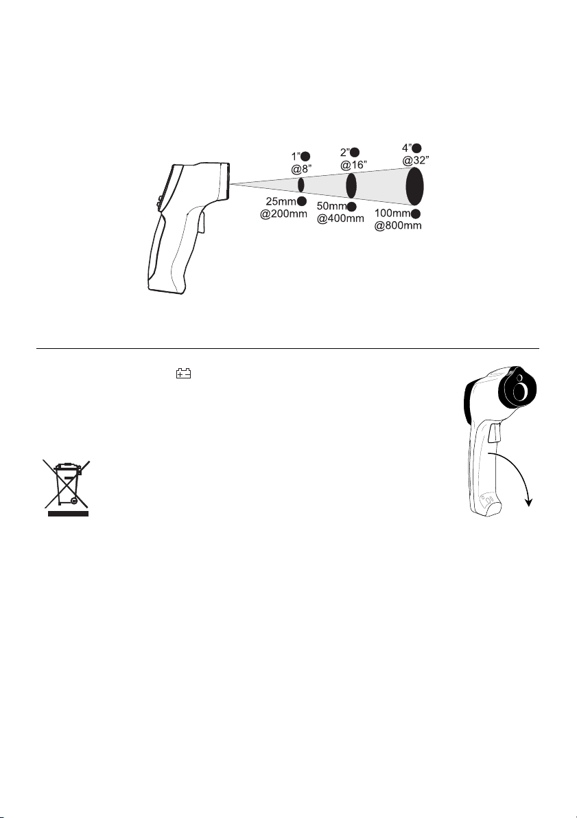
Field of View
The meter’s field of view is 8:1. For example, if the meter is 8 inches from the target (spot), the
diameter of the target must be at least 1 inch. Other distances are shown in the field of view
diagram. Note that measurements should normally be made as close as possible to the device
under test. The meter can measure from moderate distances but the measurement may be affected
by external sources of light. In addition, the spot size may be so large that it encompasses surface
areas not intended to be measured.
Battery Replacement
When the battery symbol
battery. The battery compartment is located behind the panel that surrounds the
meter’s trigger. The panel can be pried open near the trigger and folded down as
shown in the diagram. Replace the 9V battery and close the battery compartment
cover.
You, as the end user, are legally bound (EU Battery ordinance) to
return all used batteries, disposal in the household garbage is
prohibited! You can hand over your used batteries / accumulators at
collection points in your community or wherever batteries / accumulators
are sold!
Disposal: Follow the valid legal stipulations in respect of the disposal of
the device at the end of its lifecycle
appears in the display, replace the meter’s 9V
4
www.GlobalTestSupply.com
IR400-en-GB_v1.3 06/15
Page 5

IR Measurement Notes
1. The object under test should be larger than the spot (target) size calculated by the field of view
diagram (printed on the side of the meter and in this guide).
2. Before measuring, be sure to clean surfaces that are covered with frost, oil, grime, etc.
3. If an object's surface is highly reflective, apply masking tape or flat black paint to the surface
before measuring. Allow time for the paint or tape to adjust to the temperature of the surface it is
covering.
4. Measurements can not be made through transparent surfaces such as glass. The surface
temperature of the glass will be measured.
5. Steam, dust, smoke, etc. can obscure measurements.
6. The meter automatically compensates for deviations in ambient temperature. However, it can
take up to 30 minutes for the meter to adjust to extremely wide changes.
7. To find a hot spot, aim the meter outside the area of interest then scan across (in an up and
down motion) until the hot spot is located.
Emissivity and IR Measurement Theory
IR Thermometers measure the surface temperature of an object. The thermometer’s optics sense
emitted, reflected, and transmitted energy. The thermometer’s electronics translate the information
into a temperature reading which is then displayed on the LCD.
The amount of IR energy emitted by an object is proportional to an object's temperature and its
ability to emit energy. This ability is known as emissivity and is based upon the material of the object
and its surface finish. Emissivity values range from 0.1 for a very reflective object to 1.00 for a flat
black finish. For the Model IR400, the emissivity is set to 0.95 which is correct for 90% of typical IR
measurement applications.
5
www.GlobalTestSupply.com
IR400-en-GB_v1.3 06/15
Page 6
Specifications
Display 3-1/2 digit (1999count) LCD with backlighting
Response time Less than 1 second
Over range indication LCD will show “HI”/”LO”
Polarity Automatic (no indication for positive polarity); Minus (-) sign for
Emissivity 0.95 fixed value
Field of view D/S = Approx. 8:1 ratio (D = distance, S = spot)
Diode Laser Output <1mW, Wavelength 630~670nm, Class 2 (II) Laser
Spectral response 6~14um
Auto power off Automatic shut off after 10 seconds, approx.
Operating temperature 0
Storage temperature -20
Relative humidity 10%~90%RH operating, <80%RH storage
Power supply 9V battery, NEDA 1604A or IEC 6LR61, or equivalent
Weight 180g (6.3oz)
Dimensions 82 x 41.5 x 160mm (3.2 x 1.6 x 6.3”)
Range Resolution Accuracy
-20C to -7°C
-4F to 20°F
-7C to 332°C
20 to 630°F
Note: Accuracy is given at 18 °C to 28 °C (64 °F to 82 °F), less than 80%RH
negative polarity.
(Has 90% encircled energy at the focal point)
product
o
C to 50oC (32oF to 122oF)
o
C to 60oC (-4oF to 140oF)
0.1°F/°C ±4°C (7.5°F)
0.1°F/°C ±2% of reading + 2°C/4°F
Copyright©2013‐2015FLIRSystems,Inc.
Allrightsreservedincludingtherightofreproductioninwholeorinpartinanyform
ISO‐9001Certified
www.extech.com
6
www.GlobalTestSupply.com
IR400-en-GB_v1.3 06/15
 Loading...