

Page 1

User Manual
HDV7C-55-3 Probe
For use with the HDV700 VideoScope
Find Quality Products Online at: sales@GlobalTestSupply.com
www.GlobalTestSupply.com
Page 2
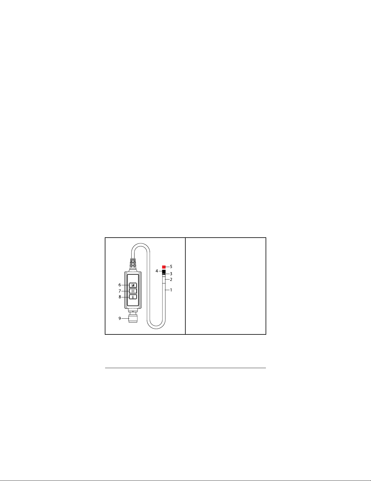
Introduction
1. Probe body
2. Camera head
3. Accessory attachment ring (unused in this model)
4. Protective threaded ring
5. Camera lens cap
6. BOOST button
7. ROTATE button
8. PARTICLE FILTER button
9. Connect to HDV700
This probe is designed for use with the HDV700 High Definition VideoScope. The probe is controlled by its three physical buttons and
the touch-screen icons on the HDV700. The HDV700 user manual
and additional translations of this probe manual are available from
the support site (see the Support section).
Please update the HDV700 firmware before use, as explained in
the HDV700 manual. This will ensure optimal functionality and compatibility with your camera probe.
The HDV700 offers many useful and convenient features including
capturing still images and video, changing camera views, and controlling worklights. Please refer to the HDV700 user manual for
complete information.
Probe Description
The camera probe head is 0.2 inches (5.5 mm) in diameter and its
probe length is 9.8 ft (3 m). The camera resolution is 640 x 480
pixels.
#NAS100124; r. AB/87921/87926; en-US
Find Quality Products Online at: sales@GlobalTestSupply.com
www.GlobalTestSupply.com
1
Page 3

Button Descriptions
to enhance the image lighting. The figure
below, on left, shows an image without boost; the figure on right
shows the same image with boost.
The red LED on the button will glow when the boost function is enabled. For best results, hold the probe very steady when using this
feature.
to rotate the image 90° up to four times,
as shown in the figure below.
Particle Filter Button
to enhance the image, removing the effects
of dust particles. The image on left, below, shows an image with no
filtering; the image on right shows the same image with filtering.
#NAS100124; r. AB/87921/87926; en-US
2
Boost Button
Use the boost button
Rotation Button
Use the rotation button
Find Quality Products Online at: sales@GlobalTestSupply.com
Press the filter button
www.GlobalTestSupply.com
Page 4

Connecting the Probe
1. Align the white dot on the probe connector with the white dot on
the monitor connector.
2. Plug the probe into the monitor unit, ensuring proper alignment
and full insertion.
3. Tighten the collar nut to secure the connection. Do not
overtighten.
CAUTION
Do not insert the probe into flammable liquid or gas.
This product is designed for industrial use only. It is not intended for use in human or other biological inspection.
CAUTION
To clean the probe, wipe with a soft cloth dampened with a mild detergent and
clean water. Do not use abrasives, corrosives (alcohol), or solvents to clean
the probe. Use a high quality lens cleaning fluid and a lint-free swab to clean
the camera and worklight lenses.
Do not disassemble the product, damage to the product and electrical shock
may occur.
Avoid direct sun exposure. Store in a cool, dry, and well-ventilated area.
The steps below explain how to safely connect the probe to the
HDV700. Always turn the HDV700 power off before replacing the
probe.
Safety
Please read and understand all safety cautions before use.
Find Quality Products Online at: sales@GlobalTestSupply.com
#NAS100124; r. AB/87921/87926; en-US
www.GlobalTestSupply.com
3
Page 5

Do not bend or force the probe end into a position
> 90°, damage to the probe could result.
Do not coil the probe to a diameter greater than 6
inches (15 cm) in use or when storing.
Replace the protective cap and tighten the protective ring when storing the probe.
The probe contains sensitive circuitry that controls
the optics and electronics of the camera. Do not
strike the probe or allow it to impact objects
forcefully.
Immerse probes only in approved liquids (see the
Specifications section).
Use a high quality cleaning fluid and swab to clean
the camera head.
#NAS100124; r. AB/87921/87926; en-US
Find Quality Products Online at: sales@GlobalTestSupply.com
www.GlobalTestSupply.com
4
Page 6

Specifications
Camera resolution
Probe Diameter 0.2 inches (5.5 mm)
Field of View
Depth of Field 0.4 to 2.4 inches (10 to 60 mm)
Probe tip length 0.78 inches (20 mm)
Probe length 9.8 ft. (3 m)
LED Worklights Four (4) white LED lamps
Operating and Storage
temperature
Relative Humidity 10 to 95 % non-condensing
Approved liquids Approved for use in brake and transmission fluid,
Ingress rating
640 x 480 pixels
90°
14 to 140℉ (-10 to 60℃)
diesel fuel, unleaded gasoline, engine oil, and
CPC hydraulic fluid (46AWS).
Probe tip and body: IP 67 (IEC 60529)
Protected from submersion in water up to 3.3 ft (1
m) for 30 minutes maximum. In use: rain,
splashes, and accidental submersion
#NAS100124; r. AB/87921/87926; en-US
Find Quality Products Online at: sales@GlobalTestSupply.com
www.GlobalTestSupply.com
5
Page 7

Two-year Warranty
FLIR Systems, Inc. warrants this Extech brand instrument to
be free of defects in parts and workmanship for two years from
date of shipment (a six-month limited warranty applies to sensors
and cables).
Calibration and Repair Services
FLIR Systems, Inc. offers calibration and repair services for
the Extech brand products we sell. We offer NIST traceable
calibra-tion for most of our products. Contact us for information on
calibra-tion and repair availability, refer to the contact information
below. Annual calibrations should be performed to verify meter
perform-ance and accuracy. Product specifications are subject to
change without notice. Please visit our website for the most up-todate product information
#NAS100124; r. AB/87921/87926; en-US
Find Quality Products Online at: sales@GlobalTestSupply.com
www.GlobalTestSupply.com
6
 Loading...