

Page 1

User Manual
HDV700 High Definition
VideoScope Kit
Find Quality Products Online at: sales@GlobalTestSupply.com
www.GlobalTestSupply.com
Page 2

Table of contents
1 Introduction..... ........................... ..... ........................... ..... ... 1
1.1 Overview .... ..... ..... ..... ..... ................. ..... ..... ..... .......... 1
1.2 Product Features ... ................. ..... ..... ..... ................. .... 1
1.3 Kit Descriptions ... ..... ................. ..... ..... ..... ................. . 1
1.4 Available Probes .... ..... ..... ................. ..... ..... ..... .......... 2
1.5 Supplied Equipment (all kits) ........ ..... ........................... . 2
1.6 Supplied Equipment (select probes) ............. ..... ..... ..... ... 2
2 Safety ........... ..... ..... ..... ..... ............ ..... ..... ..... ..... ................. 3
3 Quick Start .............................. ..... ..... ...................... ..... ..... .5
4 Product Descriptions ..... ..... ...................... ..... ..... .................6
4.1 VideoScope . ..... ..... ..... ................. ..... ..... ..... ..............6
4.2 Touch-Screen .... ..... ...................... ..... ..... ..... ..............7
4.3 Using an External Monitor.. ................................ ..... ...... 9
5 Connecting the Probe .............. ..... ..... ..... ................. ..... ..... 10
6 Powering the HDV700 ..... ................. ..... ..... ..... ................. .. 11
6.1 Power the Display Unit ... ..... ..... ..... ............ ..... ..... ..... .. 11
6.2 Battery Overview ... ..... ..... ................................ ..... .... 11
6.3 Battery Status Indicators .. ..... ................. ..... ..... ..... ..... 11
6.4 Charging the Battery ............... ..... ..... ...................... .. 11
6.5 Power Reset Button ................... ..... .......................... 12
7 Settings Menu........... ..... ..... ..... ................. ..... ..... ..... ..... .... 13
7.1 Settings Menu Overview ... ................. ..... ..... ..... ..... .... 13
7.2 Menu Item Descriptions ..... ..... ..... ................. ..... ..... ... 13
7.2.1 INFO .......... ..... ........................... ..... ..... ..... .. 13
7.2.2 IMAGE .............. ..... ..... ...................... ..... ..... 14
7.2.3 SESSION.... ..... ..... ..... ..... ............ ..... ..... ..... .. 14
7.2.4 TAG .. ..... ..... ................. ..... ..... ..... ................ 15
7.2.5 USB CARD READER. ................. ..... ..... ..... ..... 16
7.2.6 SD CARD. ..... ........................... ..... ..... ..... ..... 16
7.2.7 DATE / TIME .... ..... ........................... ..... ..... ... 17
7.2.8 LANGUAGE........ ..... ..... ..... ..... ................. ..... 18
7.2.9 MICROPHONE ................... ..... ..... ................ 18
7.2.10 AUTO POWER OFF . ..... ................. ..... ..... ..... . 18
7.2.11 REGULATORY .............................. ................ 19
8 Image and Video Recording.......... ..... ..... ..... ................. ..... . 20
8.1 Image and Video Basics..... ........................... ..... ........ 20
#NAS100121; r. AC/89755/89755; en-US ii
Find Quality Products Online at: sales@GlobalTestSupply.com
www.GlobalTestSupply.com
Page 3

Table of contents
8.2 Media Gallery ... ................................ ....................... 20
8.3 Opened Images ................................ ....................... 21
8.4 Opened Videos ........ ..... ..... ..... ................. ..... ..... ..... . 22
8.5 Recording Audio over Video................ ..... ..... ..... ..... .... 23
8.6 Downloading Media to a PC ..... ..... ..... ..... .................... 23
9 PC Interface. ................. ..... ..... ..... ................. ..... ..... ..... ..... 24
9.1 PC Interface Overview .... ..... ..... ................. ..... ..... ..... . 24
9.2 Connecting to a PC ............. ..... ........................... ..... . 24
9.3 Accessing the HDV700 Directory on the PC .......... ..... .... 24
10 Firmware Updates ...... ................. ..... ..... ..... ................. ..... . 25
10.1 Obtaining the Firmware Update File ... ..... ............ ..... ..... 25
10.2 Moving the Upgrade File to the HDV700 ........ ..... ..... ..... . 26
10.3 Executing the Firmware Update ..... ..... ..... ..... ............... 27
11 Specifications.......................... ..... ..... ..... ................. ..... .... 28
12 Limited 2–Year Warranty............... ..... ..... ..... ....................... 30
13 CUSTOMER SUPPORT .......... ..... ..... ..... ................. ..... ..... ... 31
#NAS100121; r. AC/89755/89755; en-US iii
Find Quality Products Online at: sales@GlobalTestSupply.com
www.GlobalTestSupply.com
Page 4

1
Introduction
1.1 Overview
Thank you for selecting the HDV700 High Definition VideoScope kit. The kit is
a rugged, splash proof (IP54 display unit) and waterproof (IP67 probe) video
inspection system that includes the VideoScope, a detachable camera probe,
and accessories.
The display unit works with a variety of camera probes as listed in Sections
1.3 and 1.4 below. The probes are especially designed to perform well in difficult to reach locations and areas unsafe to approach. The probes provide
sharp video and still images and can be safely submerged in fluids, as specified in the separate instructions provided with each probe.
Check for firmware updates before putting this instrument in operation to ensure full compatibility between the VideoScope and the probe. See Section
10.
The HDV700 is battery operated and its internal lithium battery can be
charged by connecting the HDV700 to an AC source using the supplied USB
AC adaptor/charger (see Section 6).
Still images and videos are stored on the supplied micro SD card, inserted in
the HDV700 right side compartment. Stored media can be downloaded to a
PC using the USB-C port (see Sections 8 and 9).
1.2 Product Features
• Large display monitor shows camera images, touch-screen icons, settings
menu, and other information.
• Image/video recording with micro SD card storage.
• PC interface for downloading images/video and updating firmware.
• Micro HDMI port for viewing images on an external monitor.
• Split screen shows forward/side view images simultaneously when using a
dual camera or a mirror accessory.
• Split-screen also compares live images with stored images.
• Internal rechargeable lithium battery runs 6 hours from a full charge.
1.3 Kit Descriptions
Kits Kit Descriptions
HDV710
HDV720
#NAS100121; r. AC/89755/89755; en-US
General Purpose VideoScope Kit with 5.5 mm × 1 m length probe
VideoScope Kit with Dual HD Camera 4.9 mm × 1 m length probe
1
Find Quality Products Online at: sales@GlobalTestSupply.com
www.GlobalTestSupply.com
Page 5

1
Introduction
HDV730 VideoScope Kit with Two-Way Articulation 3.9 mm × 1 m length probe
HDV740 VideoScope Kit with Four-Way Articulation 6.0 mm × 1 m length probe
HDV750
VideoScope Kit with Plumbing Spool and 28 mm × 30 m length probe
Note: To order the VideoScope display unit only, use part number HDV700.
1.4 Available Probes
Probe part number Description
HDV7C-55–HD-1 HD camera probe 5.5 mm x 1 m length
HDV7C-55–3 Camera probe 5.5 mm x 3 m length
HDV7C-49–dual-1 Dual HD camera probe 4.9 mm x 1 m length
HDV7C-A2–39–HD-1 Two-way articulating HD camera probe 3.9 mm x 1 m length
HDV7C-A2–45–15
HDV7C-A4–60–1
HDV7C-A4–60–3 Four-way articulating camera probe 6.0 mm x 3 m length
HDV7C-P28–30 Plumbing spool and probe 28 mm x 30 m length
Two-way articulating camera probe 4.5 mm x 1.5 m length
Four-way articulating camera probe 6.0 mm x 1 m length
1.5 Supplied Equipment (all kits)
• HDV700 High Definition VideoScope
• Camera probe
• USB-C to USB-A charging and PC interface cable
• Power adaptor with AC plugs (for US, UK, EU, AUS)
• Micro HDMI audio-visual cable
• Micro SD card (32 G)
• Printed Quick Start booklet
• Heavy duty carrying/shipping case
1.6 Supplied Equipment (select probes)
• Side view mirror accessory for HDV7C-A4–60–1 and HDV7C-A4–60–3
probes.
• 100 mm (4 in) brush for plumbing spool probe HDV7C-P28–30.
#NAS100121; r. AC/89755/89755; en-US
2
Find Quality Products Online at: sales@GlobalTestSupply.com
www.GlobalTestSupply.com
Page 6

2
CAUTION
Please read all user instructions and safety guidelines before proceeding.
WARNING
Risk of explosion if the battery is replaced using an incompatible battery type.
WARNING
Failure to use the device without observing the information provided next to the WARNING
symbol may cause serious injury or loss of life.
CAUTION
Failure to use the device without observing the information provided next to the CAUTION
label may cause damage to the product.
WARNING
HAZARDOUS ENVIRONMENTS
DO NOTuse this system in explosive environments including gasoline and alcohol storage
tanks.
FLAMMABLE GASES
DO NOTuse this device near flammable gases.
FOR INDUSTRIAL USE ONLY
AVOID EYE INJURY
DO NOT look into the LED worklight or direct the worklight toward the eyes.
Safety
If the equipment is used in a manner not specified by the manufacturer, the
protection provided by the equipment may be impaired.
The battery is not user-serviceable. DO NOT open the unit to replace the battery or to perform maintenance. Contact if the unit needs servicing or a
battery replacement.
#NAS100121; r. AC/89755/89755; en-US
3
Find Quality Products Online at: sales@GlobalTestSupply.com
www.GlobalTestSupply.com
Page 7
2
CAUTION
INCOMPATIBLE SUBSTANCES MAY DAMAGE THE PROBE
See the probe user manual for a list of specified liquids into which the probe can be
inserted.
CAUTION
The IP54 splash proof rating applies to the VideoScope display unit. The IP67 water proof
rating applies to all available probes. The right side compartment flap on the display unit
must be fully sealed for the IP54 rating to apply.
CAUTION
For articulation probes, do not operate the articulating controls with the probe in a coiled
position. This can damage the articulation controls.
Safety
#NAS100121; r. AC/89755/89755; en-US
4
Find Quality Products Online at: sales@GlobalTestSupply.com
www.GlobalTestSupply.com
Page 8

3
CAUTION
Before putting the unit into operation, ensure that it is running the latest firmware, as explained in Section 10.
Quick Start
1. If the battery status icon is showing a low charge, or if the unit will not
power up, connect the unit to an AC power source using the supplied AC
adaptor/charger, the charger connects to the USB port located on right
side compartment (see Section 6).
2. Ensure that a micro SD card is inserted in the slot located in the right side
compartment.
3. Carefully connect the camera probe as detailed in Section 5.
4. Remove the protective lens cap from the camera probe.
5. Long press the HDV700 power button (top of unit, on right), the Extech
logo will appear.
6. The camera image will then appear with touch-screen icons, battery status
icon, and date/time (see Section 4).
7. The power status LED (located next to the power button) is green when
power is on, red while charging, and blinking once per second if the ambient temperature is > 104℉ (40℃) or < 32℉ (0℃), indicating that charging
has stopped.
8. Long press the power button to switch off the unit.
#NAS100121; r. AC/89755/89755; en-US
Find Quality Products Online at: sales@GlobalTestSupply.com
www.GlobalTestSupply.com
5
Page 9

4
Figure 4.1 VideoScope description. Front view on left, back view on left.
Product Descriptions
4.1 VideoScope
1. Touch-screen and camera monitor.
2. Power LED. Green when powered, red when charging.
3. Power button. Long press ON/OFF.
4. Reset button (recessed). Press to initialize the unit if it becomes
unresponsive.
5. Micro SD card slot. Supplied card stores images and video.
6. Micro HDMI port for connecting external monitor.
7. USB-C port for PC interface and charging.
8. Microphone for recording audio over video.
9. Probe connection.
10. Lanyard post. Lanyard not supplied.
11. Adjustable tilt stand.
#NAS100121; r. AC/89755/89755; en-US
Find Quality Products Online at: sales@GlobalTestSupply.com
www.GlobalTestSupply.com
6
Page 10
4
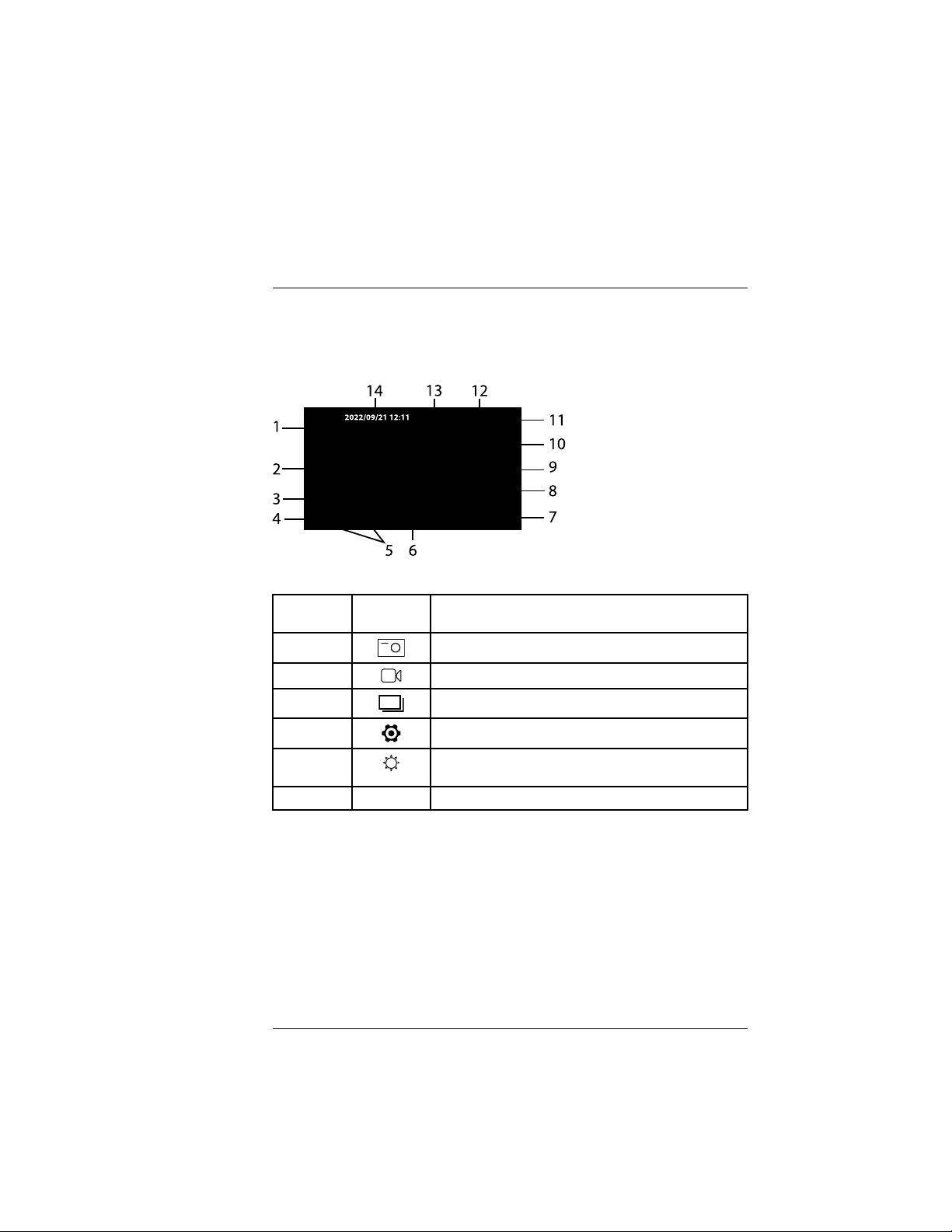
Figure 4.2 Touch-screen display.
Items in
Figure 4.1
ICON DESCRIPTION
1
Tap to capture an image.
2
Tap to start or stop a video recording.
3
Tap to open the recorded image and video media gallery.
4
Tap to open the Settings menu.
5
Brightness control icon. Use the touch-screen slider to adjust the display brightness.
6 < >
Tap to hide the display icons and view a full screen image.
Product Descriptions
4.2 Touch-Screen
When powered, the display appears as shown below. A description for each
item is provided below.
#NAS100121; r. AC/89755/89755; en-US
7
Find Quality Products Online at: sales@GlobalTestSupply.com
www.GlobalTestSupply.com
Page 11

4
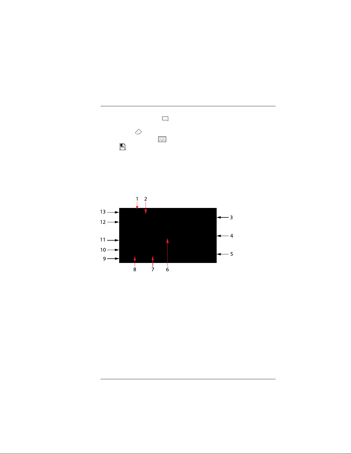
Tap to begin comparing stored images with the live camera
feed on a split-screen. When you tap the icon, the image
gallery opens. Select an image from the gallery to compare
with the live image. The screen will split, showing the
stored image and the live image side by side.
Additional touch-screen icons are active in this mode, see
figure below.
1. Live image (default position: left)
2. Stored image (default position: right)
3. Tap the icon and drag the stored image as desired, tap
icon when done
4. Swap left and right images
5. Return to Gallery to select a different image
6. Selected area of image (see step 3 above)
8
Tap to rotate image clockwise (90°, 180°, and 270°).
9
Tap to flip the image horizontally.
10
For dual camera models and for single camera models using mirror accessories, tap this icon to show a split screen
with the forward facing (F) and side facing (S) views shown
on a split screen.
For some probes, when tapped, the worklight toggles direction from side to forward or from forward to side.
11
Tap to switch the exposure compensation filter on or off.
The filter gives detail and brightens dark areas in an image.
12
Battery status icon.
13
n/a Camera image shows here.
14
2022/09/21
12:11
Date and time.
Product Descriptions
7
#NAS100121; r. AC/89755/89755; en-US
8
Find Quality Products Online at: sales@GlobalTestSupply.com
www.GlobalTestSupply.com
Page 12

4
Product Descriptions
4.3 Using an External Monitor
The micro HDMI port, inside the right side compartment, can be used to connect the HDV700 to an external monitor’s HDMI port. The external monitor will
then show the camera images and other HDV700 display information.
#NAS100121; r. AC/89755/89755; en-US
Find Quality Products Online at: sales@GlobalTestSupply.com
www.GlobalTestSupply.com
9
Page 13

5
Figure 5.1 Connecting the probe to the monitor unit
Connecting the Probe
With the display unit powered OFF, connect a probe to the display unit as described below. The connection is made at the top of the display unit. The connector location is shown in Section 4.
Each probe is supplied with its own user manual, please refer to the probe
user manual for complete information.
1. Align the white dot on the probe connector with the dot on the display
connector.
2. Carefully plug the probe into the display unit.
3. Tighten the connecting collar to secure the probe connection.
#NAS100121; r. AC/89755/89755; en-US
10
Find Quality Products Online at: sales@GlobalTestSupply.com
www.GlobalTestSupply.com
Page 14

6
Figure 6.1 Battery status icon stages
Powering the HDV700
6.1 Power the Display Unit
Long press the power button to power ON or OFF. The power button is located on the top of the HDV700, on the right, as shown in Section 4. Check
the battery status indicator, located on the upper right corner of the display,
and charge the battery if necessary before using the instrument.
6.2 Battery Overview
The HDV700 is supplied with an internal, rechargeable lithium battery. The
battery cannot be replaced or serviced in the field, please contact customer
support for assistance. The HDV700 can operate for 6 hours from a full
charge (at room temperature).
6.3 Battery Status Indicators
The battery status indicator is shown on the display on the top right corner.
Three bars indicates a fully charged battery. When the unit is charging, and
the unit is powered on, a lightning bolt symbol is shown in the indicator.
As shown below, the battery is fully charged in image no. 1. In images 2 and 3
the battery energy is decreasing until it is depleted in image no. 4. Image no.
5 shows the icon’s appearance when actively charging.
The power status LED (located next to the power button) is green when power
is on, red while charging, and blinking once per second if the ambient temperature is > 40℃ (104℉) or < 0℃ (32℉), indicating that charging has stopped.
6.4 Charging the Battery
A USB-C cable is supplied and is used to connect the HDV700 to the supplied
AC adaptor/charger (5V / 3A). The USB port is located in the HDV700 right
side compartment. Connect the adaptor to an AC power source to charge.
Do not attempt to charge the battery if the ambient temperature is > 104℉
(40℃) or < 32℉ (0℃).
The AC charger is rated for 100 to 240 V AC (50/60 Hz) and international
power adaptors are supplied (for US, UK, EU, AUS). The HDV700 will also
charge while connected to a PC, but the charge time increases. The time
#NAS100121; r. AC/89755/89755; en-US
11
Find Quality Products Online at: sales@GlobalTestSupply.com
www.GlobalTestSupply.com
Page 15

6
Powering the HDV700
required to fully charge the battery, from a low battery condition, is typically
3.5 hours using the AC adaptor.
6.5 Power Reset Button
If the HDV700 display freezes or otherwise malfunctions, open the right side
compartment, and short press the reset button. The button is recessed and
requires a pin or similar tool to reach.
When the reset button is pressed the HDV700 switches off. Power up the
HDV700 to begin using the instrument.
#NAS100121; r. AC/89755/89755; en-US
Find Quality Products Online at: sales@GlobalTestSupply.com
www.GlobalTestSupply.com
12
Page 16

7
Figure 7.1 Settings Menu.
to open the menu. The menu has two
pages, tap the up/down arrow touch-screen icons to scroll. Tap a menu item
to access it.
7.2 Menu Item Descriptions
Each menu item is detailed below.
7.2.1 INFO
Tap to open the Information menu.
Figure 7.2 Information Settings Menu
Settings Menu
7.1 Settings Menu Overview
The Settings menu allows you to quickly and easily customize the HDV700.
Tap the Settings touch-screen icon
View the firmware version (2) and serial number (3). Tap FIRMWARE UPGRADE (4) to upgrade the firmware. Tap FACTORY DEFAULT (5) to reset all
user programmable settings. See Section 14 for details on firmware upgrading. Tap the left arrow (1) to return to the main menu.
#NAS100121; r. AC/89755/89755; en-US
13
Find Quality Products Online at: sales@GlobalTestSupply.com
www.GlobalTestSupply.com
Page 17

7
Figure 7.3 Image Settings Menu
Figure 7.4 Sessions menu.
Settings Menu
7.2.2 IMAGE
Tap to open the Image Brightness and Contrast control menu.
Tap and drag the sliders (2) as desired. Tap DEFAULT (3) to reset the image
settings. Tap the left arrow (1) to return to the main menu.
7.2.3 SESSION
In the Session menu you can create folders in which to organize images and
video. You can also rename and delete existing folders.
1. Tap to return to main menu.
2. Tap to open the TAG menu (see next section).
3. Tap to create a new media folder. Tap the touch-screen keyboard charac-
4. Tap to rename a highlighted folder. Note that you can only rename folders
#NAS100121; r. AC/89755/89755; en-US
ters to name the new folder, tap DONE when completed.
that you have created. The MEDIA folder is a system folder and cannot be
renamed.
14
Find Quality Products Online at: sales@GlobalTestSupply.com
www.GlobalTestSupply.com
Page 18

7
Figure 7.5 TAG menu.
Settings Menu
5. Tap to delete a highlighted folder. Only folders that you have created can
be deleted.
6. Scroll down to the next page (if any).
7. The top number shows the current page. The bottom number shows the
total number of pages. As you create more folders, pages will be automatically added as needed.
8. Scroll to prior pages (if any).
9. List of folders. In this example, New Folder is selected, which is a folder
created by the user.
7.2.4 TAG
Tags are custom text messages that can be superimposed on images. Tags
can include up to 20 characters. Up to three text strings can be added to images. You can select on which corner the messages are affixed and how the
messages appear (in a horizontal string or stacked vertically).
Tags are only superimposed on images that are taken AFTER you create the
tags. If you wish to add text to existing images, see Section 8. To stop adding
text tags to images, de-select the currently selected folder (item no. 8 in Figure below).
1. Tap to return to main menu.
2. Tap to select the folder in which tagged images will be stored. Note that
this will take you temporarily back to the Session menu (see previous
section).
#NAS100121; r. AC/89755/89755; en-US
Find Quality Products Online at: sales@GlobalTestSupply.com
www.GlobalTestSupply.com
15
Page 19

7
Figure 7.6 Tags shown horizontally (1) and vertically (2).
appears, when the HDV700 is
connected to a PC. While connected, you can move images and video from
the SD card to a PC and update the firmware. See Section 9, for PC interface
information, and Section 10, for firmware updating.
7.2.6 SD CARD
Tap SD CARD to open the menu.
Settings Menu
3. Tap to add, rename, or delete tags. If three tags are already created, you
cannot create a new one. Highlight and delete a tag if you wish to make
room for a new tag. When creating tags, the touch-screen keyboard will
appear. Type the tag text and then tap DONE when completed.
4. Tap the corner that you wish to affix the tag(s).
5. Tap to format the tags so that they are stacked vertically on the selected
corner of the images (see Figure 7.6 below).
6. Tap to format the tags so that they are shown horizontally on the selected
corner of the images.
7. User-created tags.
8. Tap to enable the highlighted folder where the tagged images will be
stored.
9. Folder name where images will be stored.
7.2.5 USB CARD READER
There are no programmable settings to adjust in this menu. The menu text
turns from grey to white, and the USB icon
#NAS100121; r. AC/89755/89755; en-US
16
Find Quality Products Online at: sales@GlobalTestSupply.com
www.GlobalTestSupply.com
Page 20

7
Figure 7.7 SD Card Settings Menu
Figure 7.8 Date/Time Settings Menu
Settings Menu
The available memory for images only (2), video only (3), and total memory
(4) is displayed. You can delete all files by tapping DELETE ALL FILES (5) or
you can format a new SD card by tapping FORMAT SD CARD (6). Tap the left
arrow (1) to return to the main menu.
Do not use SD cards that were formatted on another device, as the filing systems may differ. Always format SD cards with the HDV700 before use (the
supplied card is formatted at the factory).
For additional SD card information, see the Specifications (Section 11).
7.2.7 DATE / TIME
Tap to open the Date/Time menu.
Use the touch-screen arrows to set the date (2) and the time (3). Tap the up/
down arrows (4) to select the display format for month (MM), day (DD), and
year (YY): MM/DD/YY, DD/MM/YY, or YY/MM/DD. Tap the up/down arrows (5)
#NAS100121; r. AC/89755/89755; en-US
17
Find Quality Products Online at: sales@GlobalTestSupply.com
www.GlobalTestSupply.com
Page 21

7
Figure 7.9 Language Settings Menu
Figure 7.10 APO Settings Menu
Settings Menu
to select the 12 or 24 hour clock. Tap the left arrow (1) to return to the main
menu.
7.2.8 LANGUAGE
Tap to open the Language menu.
Tap the desired language (2). Tap the up/down arrow icons (3) to scroll pages.
Tap the left arrow (1) to return to the main menu.
7.2.9 MICROPHONE
Tap ON or OFF to enable or disable the microphone function. Audio narrative
can then be recorded with each video. The microphone opening is just below
the display, as shown in the product description section.
7.2.10 AUTO POWER OFF
Tap to open the APO menu.
To set APO, tap 5, 10, 20, 30 minutes (3) or Disable (2). Tap the left arrow (1)
to return to the main menu.
#NAS100121; r. AC/89755/89755; en-US
Find Quality Products Online at: sales@GlobalTestSupply.com
www.GlobalTestSupply.com
18
Page 22

7
Figure 7.11 Regulatory information page.
Settings Menu
7.2.11 REGULATORY
Tap this item to view safety verifications, regulatory compliance certifications,
and more.
#NAS100121; r. AC/89755/89755; en-US
19
Find Quality Products Online at: sales@GlobalTestSupply.com
www.GlobalTestSupply.com
Page 23

8
to save still images and tap the vid-
eo record button
to start/stop video recording.
With a connected microphone, you can record narration audio over videos
(see Section 8.5 for details).
Media are stored on the supplied micro SD card (inserted in the right-side
compartment). For information regarding the number of images and length of
video that can fit on a variety of SD card sizes, see the Specifications (Section
11).
Images and video can be downloaded to a PC using the USB connector in
the right side compartment of the HDV700, see Section 9 for additional
information.
8.2 Media Gallery
Once images and video are recorded you can view them directly in the
HDV700 media gallery by tapping the Gallery touch-screen icon
. In the
Gallery, tap the media icon to toggle between Images
and Video . Tap a
thumbnail to open the image or video. Refer to the call-out below for more
details.
Figure 8.1 Media Gallery
Image and Video Recording
8.1 Image and Video Basics
The HDV700 allows you to capture still images (.jpg) and video (.mov). Tap
the image capture touch-screen icon
1. Current folder.
2. Date and Time.
#NAS100121; r. AC/89755/89755; en-US
20
Find Quality Products Online at: sales@GlobalTestSupply.com
www.GlobalTestSupply.com
Page 24

8
Figure 8.2 Opened Image in Media Gallery
Image and Video Recording
3. Media thumbnails.
4. Up arrow. Scroll gallery pages.
5. Selected page (top number) and total number of pages (bottom number).
6. Down arrow. Scroll gallery pages.
7. Delete media.
8. Tap to toggle image and video thumbnails.
9. Tap to open the folder utility where you can select/create media folders.
10. Tap the arrow to exit the gallery.
8.3 Opened Images
When you tap an image thumbnail, the image will open on the HDV700 display. While the image is opened, you can type text onto the image, delete the
image, and perform other actions as described in the call-out below. Note that
in the Tags menu (in Settings) you can add reusable text tags to images, see
Section 7.
1. Name of folder in which the image is stored.
2. Date/Time stamp.
3. Up arrow to scroll to next image.
4. Image filename.
5. Down arrow to scroll to prior image.
6. Tap trash icon to delete image.
7. Tap to toggle the image and video galleries.
#NAS100121; r. AC/89755/89755; en-US
Find Quality Products Online at: sales@GlobalTestSupply.com
www.GlobalTestSupply.com
21
Page 25
8
and type a comment using the touch-screen
keyboard; tap DONE when finished. Delete comments by tapping the
eraser icon
or open the keyboard again to amend comments, by press-
ing the keyboard icon
. When satisfied with your comment, tap the disc
icon
to save the comments with the image.
9. Tap to create or rename a folder.
10. Return to the main thumbnail gallery.
8.4 Opened Videos
When you tap a video thumbnail, the video will open on the HDV700 display.
Tap the screen to stop/restart the video. You can perform other actions as described in the call-out below.
Figure 8.3 Opened Video in Media Gallery
Image and Video Recording
8. Tap the comments icon
1. Name of folder in which the image is stored.
2. Date/Time stamp.
3. Up arrow to scroll to next video.
4. Video filename.
5. Down arrow to scroll to prior video.
6. Tap to play the video.
7. Video time line with minutes and seconds display (MM’SS”)
Find Quality Products Online at: sales@GlobalTestSupply.com
8. Tap to pause video.
9. Tap trash icon to delete media.
10. Tap to toggle the image and video galleries.
11. Tap to take a screen shot of any point in the video.
12. Tap to create or rename a folder.
13. Return to the main thumbnail gallery.
#NAS100121; r. AC/89755/89755; en-US
www.GlobalTestSupply.com
22
Page 26

8
to access
the menu, scroll to the Microphone setting, and tap ON. You can then add narrative audio while recording video. The audio can be heard upon video
playback.
The microphone is located just below the display on the left, as shown in Section 4, Product Description.
8.6 Downloading Media to a PC
The HDV700 is equipped with a PC interface. Connect the supplied USB cable to the USB port, located under the flap on the right side of the unit, and to
a PC USB port.
The HDV700 will be recognized by the PC as a new external storage drive.
Simply drag files out of, and into (in the case of firmware upgrades), the
HDV700 drive. Media files are located in the MEDIA folder, the firmware file
must be kept in the root directory, not in a folder. See Sections 9 and 10 for
additional information regarding the PC interface and firmware updates.
Image and Video Recording
8.5 Recording Audio over Video
Voice-over recordings can be combined with videos.
Activate the microphone function in the Settings menu. Press
#NAS100121; r. AC/89755/89755; en-US
23
Find Quality Products Online at: sales@GlobalTestSupply.com
www.GlobalTestSupply.com
Page 27

9
Figure 9.1 Connect to a PC using the supplied USB-C (HDV700 port) to USB-A (PC port)
cable.
PC Interface
9.1 PC Interface Overview
The PC interface utility allows you to download images and video to your PC.
The PC interface also allows you to upgrade the HDV700 firmware, see Section 10.
When connected to a PC, the HDV700 also charges its battery. For quicker
charging, connect the HDV700 to an AC power source using the supplied AC
adaptor and USB cable, see Section 6.
9.2 Connecting to a PC
The HDV700 is supplied with a USB-C to USB-A cable, connect the USB-C
end of the cable to the USB port in the HDV700 right side compartment and
the other end to the PC USB-A port. Depending on the type of USB port on
your PC, you may need to use a USB adaptor to connect correctly.
9.3 Accessing the HDV700 Directory on the PC
When successfully connected, the PC will show the HDV700 as an external
drive. Open the drive to see its root directory which contains the firmware file
and a set of folders. The Media folder is where images and videos, captured
by the HDV700 , are stored. In addition, the user may create custom folders to
organize images and video as explained in Sections 7 and 8. There may be
other folders present that are for system use only.
You can then move images and video from your media folders onto your PC
hard drive.
The HDV700 root directory is where you place firmware update files. See Section 10 for firmware upgrade details.
#NAS100121; r. AC/89755/89755; en-US
24
Find Quality Products Online at: sales@GlobalTestSupply.com
www.GlobalTestSupply.com
Page 28

10
Figure 10.1 Click ‘DOWNLOADS’.
Figure 10.2 Click the ‘Software and Firmware’ item from the options list.
#NAS100121; r. AC/89755/89755; en-US
25
Firmware Updates
To update the firmware, carefully follow the steps in the following sections.
The FLIR website is updated periodically to make improvements and so the
screen examples, below, may not match the current format or configuration
exactly. If you need assistance please contact.
10.1 Obtaining the Firmware Update File
1. Go to the support site
2. Click on the DOWNLOADS menu heading, as shown.
3. Click Software and Firmware as shown.
4. Type your Email Address to log in or to create an account, as shown.
Click Continue.
Find Quality Products Online at: sales@GlobalTestSupply.com
www.GlobalTestSupply.com
Page 29

10
Figure 10.3 Follow the steps to complete the download process.
Firmware Updates
5. For Figure 15.3, below, 1. Type HDV700 in the search field; 2. Select FLIR
/ Extech Meters Software from the pull-down menu; 3. Select Extech
Software from the pull-down menu; 4. Click SEARCH; 5. Click the update
file to download it to your PC.
10.2 Moving the Upgrade File to the HDV700
1. As explained in Section 9, PC Interface, connect the HDV700 to the PC
using the supplied USB cable.
2. When the HDV700 is physically connected to the PC, the PC should recognize the HDV700 as an external storage drive. For Windows, the
HDV700 drive will be given a drive letter in File Explorer (E:, for example).
For Mac, the HDV700 drive icon will appear on the desktop.
3. Drag the downloaded firmware file from your PC to the root (top level) directory of the HDV700 as shown in the Windows example below in Figure
10.4.
NOTE
Drag only the update file into the HDV700 root directory. Do not drag other files or folders
that may accompany the update file (readme.txt, for example).
Rename the existing firmware file before loading the new update file. This will allow you
to revert to the earlier firmware version if necessary.
4. Safely eject the HDV700 from the PC (for Windows, right-click the drive
letter in File Explorer and select Eject; For Mac, drag the drive icon into
the Trash).
5. Physically disconnect the HDV700 from the PC.
#NAS100121; r. AC/89755/89755; en-US
Find Quality Products Online at: sales@GlobalTestSupply.com
www.GlobalTestSupply.com
26
Page 30

10
Figure 10.4 Windows PC example: Moving the update file to the HDV700 root directory.
Firmware Updates
10.3 Executing the Firmware Update
1. With the HDV700 disconnected from the PC, press the HDV700 Settings
button to open the Settings menu.
2. Navigate to the INFO menu, tap INFO to open it, and then tap FIRMWARE
UPGRADE; confirm the action when prompted.
3. Depending on the specific firmware, the HDV700 may automatically cycle
power and restart with the new firmware active, or you may have to manually restart the HDV700 after it switches off.
4. After restarting, verify that the new firmware version number is displayed in
the INFO settings menu.
5. If you have questions, or run into problems upgrading, please contact
#NAS100121; r. AC/89755/89755; en-US
Find Quality Products Online at: sales@GlobalTestSupply.com
www.GlobalTestSupply.com
27
Page 31
11
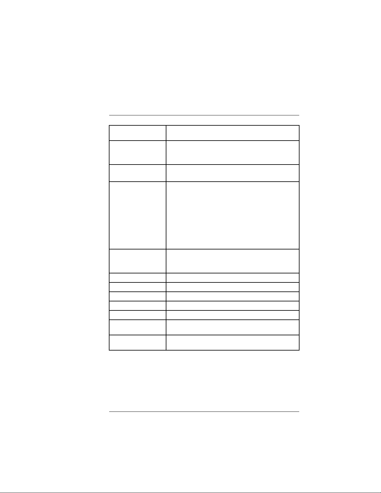
Specifications
Monitor 5 in. (12.7 cm) diagonal colour capacitive touch-screen dis-
Stored images file
format
Stored video file format MP4 format (1280 x 720)
Media storage capacity
Connectivity USB 2.0 for PC interface and battery charging
Probe Depth of Field 10 to 100 mm (all compatible probes)
Operating temperature 14 to 140℉ (–10 to 60℃)
Storage temperature -4 to 140℉ (–20 to 60℃)
Relative humidity 10 to 95%, non-condensing
Altitude 3281 ft. (1000 m)
Dimensions (L x W x H)
VideoScope only
Weight (VideoScope
only)
play (800 x 480)
JPEG format (1280 x 720)
Comments can be added directly onto images in the Media
Gallery
Audio can be recorded over video
32 G micro SD card (supplied); 64 G maximum size.
SD card capacity examples:
4 GB: total images 31,130; video length: 135 minutes
8 GB: total images 62,259; video length: 270 minutes
16 GB: total images 124,518; video length: 539 minutes
32 GB: total images 249,037; video length: 1079 minutes
Larger SD card sizes will accommodate proportionately longer
video lengths and image totals.
Micro HDMI connection for displaying camera images on an
external monitor (NTSC / PAL compatibility)
6.4 x 5.0 x 1.2 in. (16.2 x 12.8 x 3.0 cm)
1.5 lbs. (705 g)
#NAS100121; r. AC/89755/89755; en-US
Find Quality Products Online at: sales@GlobalTestSupply.com
www.GlobalTestSupply.com
28
Page 32

11
Specifications
Power supply Rechargeable lithium ion battery (4900 mAh)
3.5 hours charging and 6 hours operation at 79℉ (26℃)
Do not charge the battery if the ambient temperature is >
104℉ (40℃) or < 32℉ (0℃)
AC adaptor/charger (supplied) for US, UK, EU, and AUS plugs.
Output is rated 100 to 240 VAC ±10%, 50/60 Hz. Input is rated
5.0 V DC, 3.0 A
Ingress protection IP54 dust- and splash-proof rating for display unit
IP67 water-proof rating for probes
Drop-proof 3.3 ft. (1 m)
Approved liquids for
camera probe
immersion
Hazardous substance
compliance
EMC compliance EN 55035 (Immunity)
See separate instructions provided with probe or contact
WEEE 2012/19/EU
RoHs 2011/65/EU
REACH Regulation EC 1907/2006
CA 65
EN 55032 (Emissions)
FCC Title 47 part 15, sub-part B
#NAS100121; r. AC/89755/89755; en-US
Find Quality Products Online at: sales@GlobalTestSupply.com
www.GlobalTestSupply.com
29
Page 33

12
Limited 2–Year Warranty
FLIR Systems, Inc. warrants this Extech brand instrument to be free of defects
in parts and workmanship for two (2) years from date of purchase. To view the
full warranty please visit the site below.
#NAS100121; r. AC/89755/89755; en-US
Find Quality Products Online at: sales@GlobalTestSupply.com
www.GlobalTestSupply.com
30
 Loading...