

Page 1
User's Guide
Video Borescope
Models BR200 and BR250
Page 2
Introduction
Congratulations on your purchase of this Extech BR200 (17mm camera head) or BR250
(9mm camera head) Video Borescope. This instrument was designed for use as a remote
inspection device. It can be used to peer into tight spots and then supply real-time video
and images that can be recorded. Typical applications include HVAC inspection,
automotive inspection, cable routing, and automotive/boat/aircraft inspection. This meter is
shipped fully tested and, with proper use, will provide years of reliable service.
Features
• 3.5 '' TFT-LCD palm LCD monitor with high resolution
• The image head and the cable are water resistant when the unit is fully assembled
(the monitor and the camera are not water resistant)
• Wireless and hard-wired functionality
• The monitor records video and images
• SD card capacity: 16G
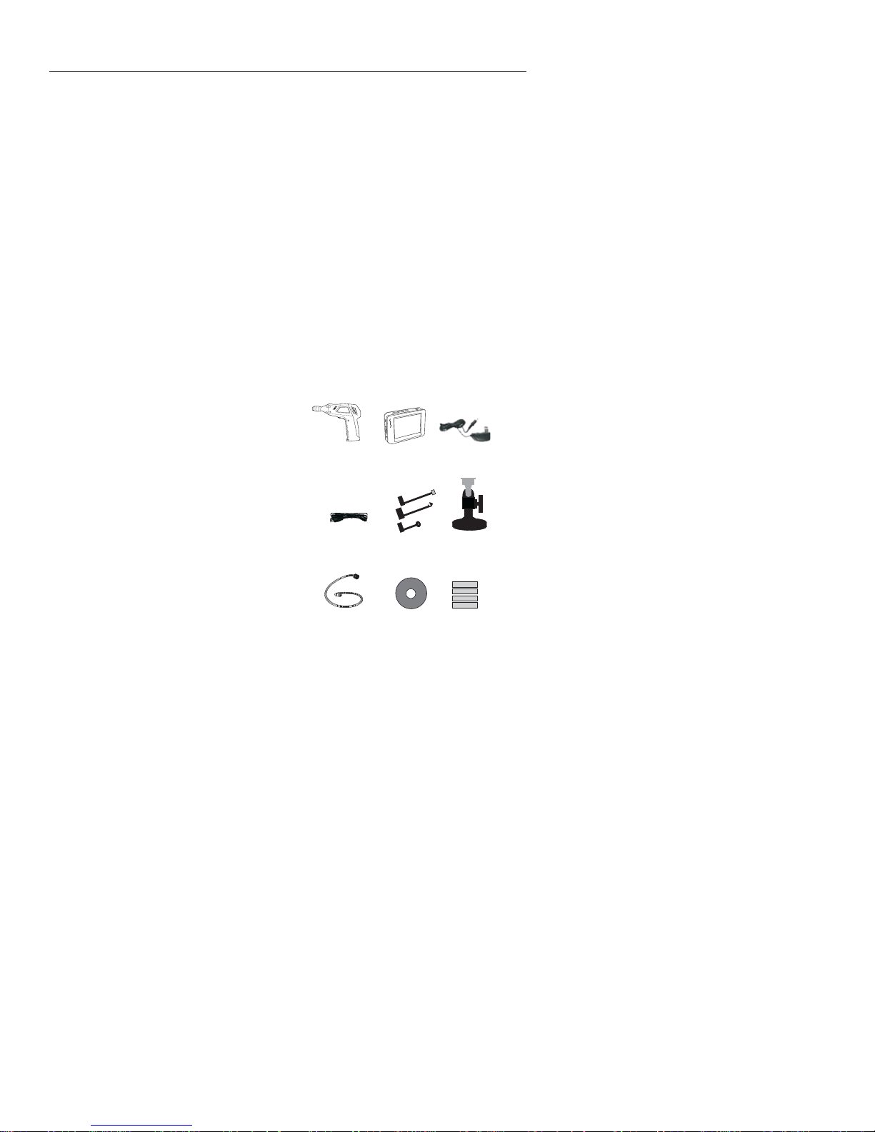
Supplied Equipment
1. Camera
2. LCD Monitor
3. Monitor Adaptor
12 3
4. Adaptor cable
5. Accessory Magnet / Hook / Mirror(BR200)
6. Magnetic mount
7. Flex cable and camera head
8. Software
9. 4 AA Batteries
2
4
7
56
89
BR200-BR250 V4.3 8/09
Page 3
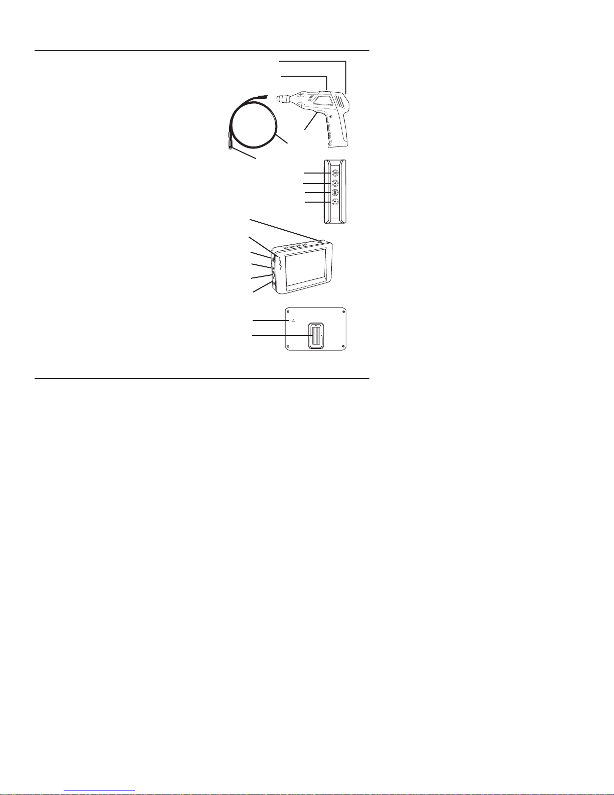
Description
1 Signal output
2 Power Indicator
3 Power On/Off, Dimmer
4 Flexible tube
5 Camera head and LED’s
6 OK
7 Up, video or jpg
8 Menu
9 Down. Channel select (4)
10 Power On/Off
11 Power Indicator
12 USB Socket
13 Video output
14 SD card socket
15 Power supply socket
16 Reset
17 Signal input
10
11
12
13
14
15
16
17
1
2
3
4
5
6
7
8
9
Warranty
EXTECH INSTRUMENTS CORPORATION (A FLIR COMPANY) warrants this instrument
to be free of defects in parts and workmanship for one year from date of shipment (a six
month limited warranty applies to sensors and cables). If it should become necessary to
return the instrument for service during or beyond the warranty period, contact the
Customer Service Department at (781) 890-7440 ext. 210 for authorization or visit our
website www.extech.com for contact information. A Return Authorization (RA) number
must be issued before any product is returned to Extech. The sender is responsible for
shipping charges, freight, insurance and proper packaging to prevent damage in transit.
This warranty does not apply to defects resulting from action of the user such as misuse,
improper wiring, operation outside of specification, improper maintenance or repair, or
unauthorized modification. Extech specifically disclaims any implied warranties or
merchantability or fitness for a specific purpose and will not be liable for any direct, indirect,
incidental or consequential damages. Extech's total liability is limited to repair or
replacement of the product. The warranty set forth above is inclusive and no other
warranty, whether written or oral, is expressed or implied.
3
BR200-BR250 V4.3 8/09
Page 4
Installation
Install the batteries into the instrument body, charge the monitor battery, connect the camera
and flexible tube to the body, insert the micro SD card. Install any accessory as needed.
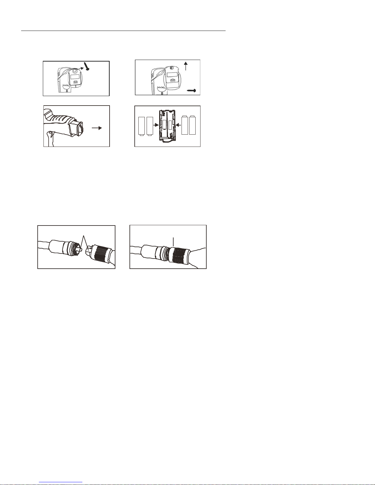
Battery Installation
Connect Monitor Power
The monitor has a rechargeable battery. Plug in the AC adaptor and connect the cable to
the DC5V socket on the monitor. The power indicator will light in red (or the battery
capacity icon on LCD of monitor will blink, indicating that it is charging - and will turn off
after a full charge)
Connect the camera and flexible tube
Connect the camera tube to the instrument body; ensure that the keyed ends are properly
aligned. Once aligned, tighten the knurled knob to hold the connection firmly in place.
4
BR200-BR250 V4.3 8/09
Page 5

Inserting the micro SD card
Insert card with arrow pointing toward slot. Gently apply pressure until card locks into
the spring loaded slot. To remove from unit, gently push the card inward and then
release to eject it from the card slot.
Installing the accessory tools (BR200)
The included accessories (mirror, hook and magnet) all attach to the camera in the same
manner. Refer to the diagrams below:
Attaching the Monitor to the instrument body
5
BR200-BR250 V4.3 8/09
Page 6

Connect the USB Cable
Use the USB cable to connect the monitor to a PC. The USB online icon will appear
on the PC. Open My Computer on the PC, and locate the Mobile Disk. The
Mobile disk can be used and accessed in the same manner as any external hard
drive.
Video Output
Insert the video cable into the VIDEO OUT socket on the monitor. Insert the other
end of the cable into the VIDEO IN jack of a TV or other monitor. The LCD Monitor
will output a high quality video image.
Installing the Magnetic bracket
The magnetic bracket slides onto the rear of the monitor for convenient placement
and viewing.
6
BR200-BR250 V4.3 8/09
Page 7

Operation
Basic Operation
1. Turn the ON/OFF dial switch to power the camera. The power indicator will switch
on. The switch then acts as a dimmer for the two LEDs on the imager head of the
camera.
2. Press and hold the monitor power switch for at least 2 seconds and the power
indicator will illuminate green and a Welcome screen will appear.
3. Before attaching the monitor to the instrument body, press the down arrow button to
select channel 4. The real time image will appear on the display LCD monitor.
Note. If the picture does not properly syncronize or has poor color, check the
Video System Settings and change from “NTSC” to ‘PAL” or vice versa. This
should fix the condition..
4. Use the up arrow to select video
5. Turn the ON/OFF dial to adjust the LED light intensity as desired.
6. The tube can be easily maneuvered into position. The tube can be bent into the
shape of the area to be examined.
7. Use the supplied accessories to help retrieve small items.
or photo mode.
Taking a Picture
In Photo mode, press OK to take a picture. The photo will automatically save to
the SD card.
Recording a Video
In Real-Time Monitoring (video) mode, press OK to begin recording; refer to the
following diagram for display icon definitions:
1. Battery capacity
2. Function icon (video or photo)
3. Recording in progress
4. Channel
5. Date
6. Time Stamp
7. REC Time remaining
8. SD card
12
2009/07/28
11:12:31
5
6
3
4
CH 4
8
[0]
7
7
BR200-BR250 V4.3 8/09
Page 8

Viewing a Photo or Video
1. In the Real-Time Monitoring mode, press to
display a list of dated playback folders
2. Use the ▼▲keys to select the desired folder.
3. Press OK to open the selected folder and view
a list of photo or video files.
4. Files are listed by time followed by (VID”) for
photos or (VID) for videos
5. Use the ▼▲keys to select a file.
6. Press OK to display the selected photo or
video.
For video files:
Press OK to pause while playing.
Press again to resume.
▲ Fast Forwards the video
▼ Rewinds the video
Press to stop video
7. Press to return to menu.
8. Press again to exit.
Note: Video automatically saves to file every 30 minutes. When the SD card is filled to
capacity, the SD card icon changes to ‘F’. No video will be recorded if the SD card is not
inserted in the slot.
Delete a Single Video Or Photo
1. In the Real-Time Monitoring mode, press to
display a list of dated playback folders
2. Use the ▼▲keys to select the desired folder.
3. Press OK to open the selected folder and view
a list of photo or video files.
4. Files are listed by time followed by (VID”) for
photos or (VID) for videos
5. Use the ▼▲keys to select a file.
6. Press and HOLD the button, the display will
show ‘DELETE CURRENT FILE?’
7. Use the arrow keys to select YES or NO
8. Press OK to accept selection.
9. Press twice to exit the Delete screen.
2009-06-10
13:00:24 VID”
13:00:24 VID”
13:00:24 VID”
13:00:24 VID
2009-06-10
13:00:24 VID”
13:00:24 VID”
13:00:24 VID”
13:00:24 VID
0001/0004
0001/0004
Delete a File Folder
To delete a folder, use the same instructions for deleting a single video or photo. The
only additional concern is that if a folder is not empty it cannot be deleted. Delete all of
the files in a folder before deleting the folder. If the user attempts to delete a folder that is
not empty, the following message will appear: FOLDER NOT EMPTY
8
BR200-BR250 V4.3 8/09
Page 9

Video Display on a PC
Several methods are available to playback or to copy video files on a PC. When
connected, the files will become available as new drives on the PC.
1. SD card adaptor: Insert the mini SD card into the SD adaptor and then insert the
adaptor into the PC SD slot (if available)
2. USB adaptor: Insert the mini SD card into a USB adaptor and plug into a USB port.
3. USB cable. Connect the USB cable from the camera to the PC.
Note: If the *.avi video files will not play on any installed media software, a software plugin is available on the supplied CD which will allow compatibility with Media Player.
Settings Mode
Press and hold for at least two seconds to enter the Settings Mode.
Language Settings
1. In Settings Mode, use the arrow keys to select SYSTEM SETTING (green icon).
2. Press OK to call up the SYSTEM icon list
3. Use the arrow keys to highlight the Language icon (globe)
4. Press OK and the Language icon list will appear (flags)
5. Use the arrow keys to highlight the desired language
6. Press OK to select the highlighted language and exit
Video System Settings
1. In Settings Mode, use the arrow keys to select SYSTEM SETTING (green icon).
2. Press OK to call up the SYSTEM icon list
3. Use the arrow keys to highlight the Video System icon (yellow)
4. Press OK and the Video format selections will appear (NTSC, PAL)
5. Use the arrow keys to highlight the desired format
6. Press OK to select the highlighted format and exit
Format and Erase Media
1. In Settings Mode, use the arrow keys to select SYSTEM SETTING (green icon).
2. Press OK to call up the SYSTEM icon list
3. Use the arrow keys to highlight the FORMAT icon (blue)
4. Press OK and the FORMAT selection screen will appear (YES, NO)
5. Use the arrow keys to highlight the desired response
6. Press OK to accept the selection and exit
Restoring Factory Default Settings
1. In Settings Mode, use the arrow keys to select SYSTEM SETTING (green icon).
2. Press OK to call up the SYSTEM icon list
3. Use the arrow keys to highlight the DEFAULT icon (red)
4. Press OK and the DEFAULT selection screen will appear (YES, NO)
5. Use the arrow keys to highlight the desired response
6. Press OK to accept the selection and exit
9
BR200-BR250 V4.3 8/09
Page 10

View Version
1. In Settings Mode, use the arrow keys to select SYSTEM SETTING (green icon).
2. Press OK to call up the SYSTEM icon list
3. Use the arrow keys to highlight the VERSION icon (green)
4. Press OK to view the version
5. Press OK again to exit
Frame Rate Setting
1. In Settings Mode, use the arrow keys to select RECORDER SETTING (red icon).
2. Press OK to call up the RECORDER options
3. Use the arrow keys to highlight the FPS (frames per second) icon
4. Press OK to open the FPS parameter
5. Use the arrows to select the frame rate: 10, 15, 20, 25, or 30
6. Press OK to confirm
Time Stamp ON OFF Setting
1. In Settings Mode, use the arrow keys to select RECORDER SETTING (red icon).
2. Press OK to call up the RECORDER options
3. Use the arrow keys to highlight the Time Stamp icon (purple)
4. Press OK to open the parameter
5. Use the arrows to select ON or OFF
6. Press OK to confirm
Date/Time Setting
1. In Settings Mode, use the arrow keys to select DATE-TIME SETTING (yellow icon).
2. Press OK to call up Date and Time Settings window
3. Use OK to tab through the fields
4. Use the arrow keys to change a field setting
5. Press the button to exit
Safety
• Do not expose instrument to moisture
• Shut off the instrument when not in use
• Remove the batteries when cleaning the instrument
• Replace all batteries at the same time
10
BR200-BR250 V4.3 8/09
Page 11

Specifications
CAMERA
Imaging Sensor CMOS
Total Pixels BR200: 704×576(PAL); 712×486(NTSC)
BR250: 640×480(PAL )
Horizontal View Angle BR200: 50 degree
Transmission Frequency 2468MHz
Minimum Illumination 0 Lux
Modulation Type FM
Bandwidth 18MHz
Power Supply 4 x AA batteries
Unobstructed Effective Range 10m
Waterproof Capacity IP67 (imager head only)
Dimensions (W D H) 186 x 145 x 41(mm) (Exclude Flexible Tube)
Weight (approx) BR200: 530g
Camera head Diameter BR200: 0.67” (17mm)
MONITOR
LCD Screen Type 3.5” TFT-LCD
Effective Pixels 320 (R.G.B.) x 240
Video System PAL/NTSC
Transmission Frequency 2414, 2432, 2450, 2468MHz
Exterior Supply Voltage 5VDC
Consumption Current (Max.) 500mA
Charge Time 3 hours
Work Time 2 hours
Video Output Level 0.9-1.3VP-P@75Ώ
Receiving Sensitivity ≤-85dBm
Dimensions (W x D x H) 100 x 70 x 25(mm)
Weight (Approx) 140g
Operating Temperature -10°C~+50°C/+14°F~+122°F
Operating Humidity (Max.) 15~85%RH
FCC Information
This device complies with part 15 of the FCC rules.
BR200: FCC-ID TW5GB8802
Operation is subject to the following two conditions:
1. This device may not cause harmful interference
2. This device must accept any interference received, including interference that may
cause undesired operation.
Calibration and Repair Services
Extech offers repair and calibration services for the products we sell. Extech also
provides NIST certification for most products. Call the Customer Care Department for
information on calibration services available for this product. Extech recommends that
annual calibrations be performed to verify meter performance and accuracy.
BR250: 45 degree
BR250: 450g
BR250: 0.36” (9mm)
11
BR200-BR250 V4.3 8/09
Page 12

Technical Support: Extension 200; E-mail: support@extech.com
Repair & Returns: Extension 210; E-mail: repair@extech.com
Product specifications subject to change without notice
For the latest version of this User Guide, Software updates, and other
up-to-the-minute product information, visit our website: www.extech.com
Extech Instruments Corporation, 285 Bear Hill Road, Waltham, MA 02451
Support line (781) 890-7440
Copyright © 2009 Extech Instruments Corporation (a FLIR company)
All rights reserved including the right of reproduction in whole or in part in any form.
12
BR200-BR250 V4.3 8/09
 Loading...