

Page 1
User Manual
Video Borescope
Models BR200 and BR250
Page 2
BR200-BR250-en-GB_v7.5 4/17
2
Introduction
Congratulations on your purchase of this Extech BR200 (17mm camera head) or BR250 (9mm
camera head) Video Borescope. This instrument was designed for use as a remote inspection
device. It can be used to peer into tight spots and then supply real-time video and images that can
be recorded. Typical applications include HVAC inspection, automotive inspection, cable routing,
and automotive/boat/aircraft inspection. This meter is shipped fully tested and, with proper use, will
provide years of reliable service.
Features
• 3.5 '' TFT-LCD palm LCD monitor with high resolution
• The image head and the cable are water resistant when the unit is fully assembled (the
monitor and the camera are not water resistant)
• Wireless and hard-wired functionality
• The monitor records video and images
• Micro SD card memory (16G max. size); Please use Class 4 (or higher) TF Flash memory card
Safety
• Do not expose instrument to moisture
• Shut off the instrument when not in use
• Remove the batteries when cleaning the instrument
• Replace all batteries at the same time
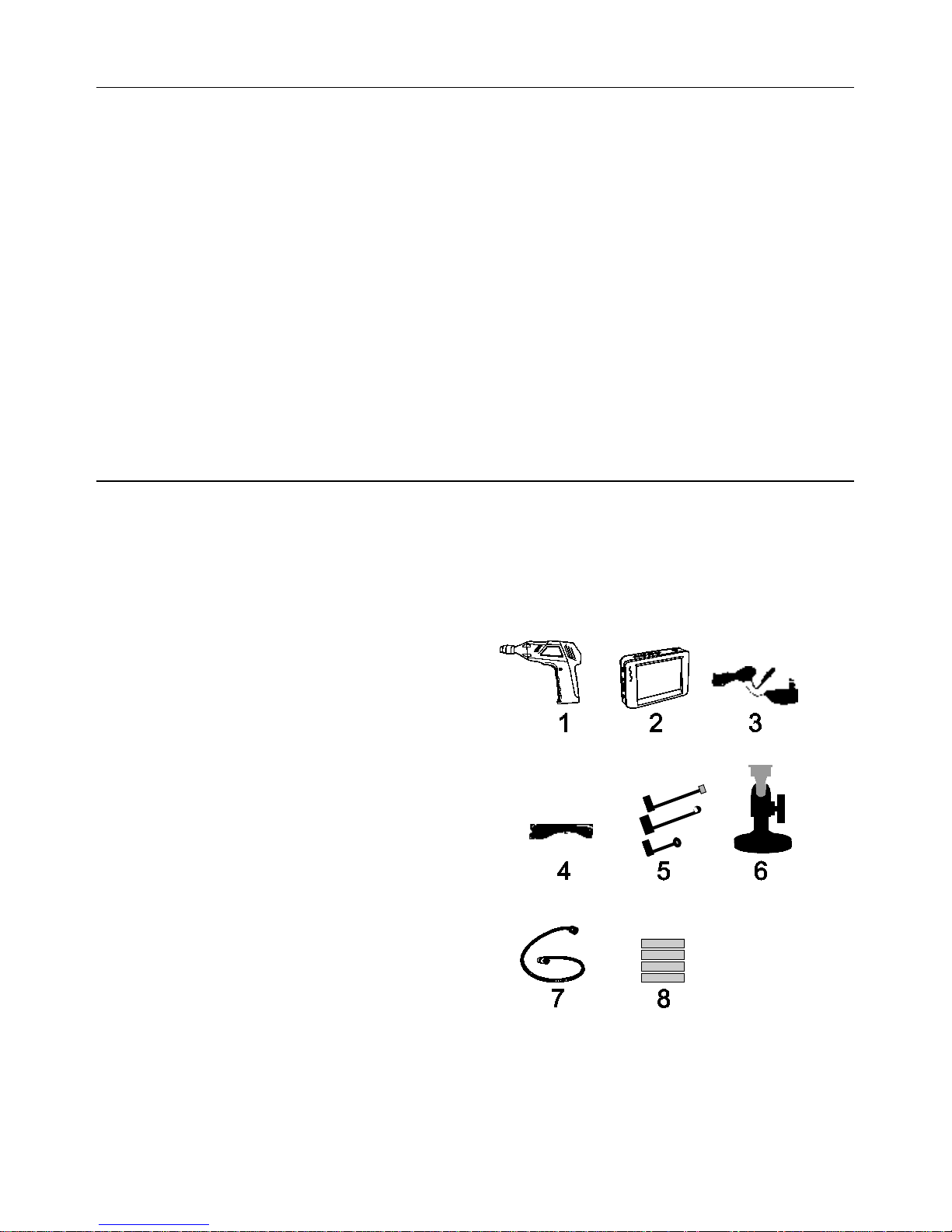
Supplied Equipment
1. Camera
2. LCD Monitor
3. Monitor Adaptor
4. Adaptor cable
5. Accessory Magnet / Hook / Mirror
6. Magnetic mount
7. Flex cable and camera head
8. 4 AA Batteries
Note: Micro SD card and adaptor (not shown)
Page 3
BR200-BR250-en-GB_v7.5 4/17
3
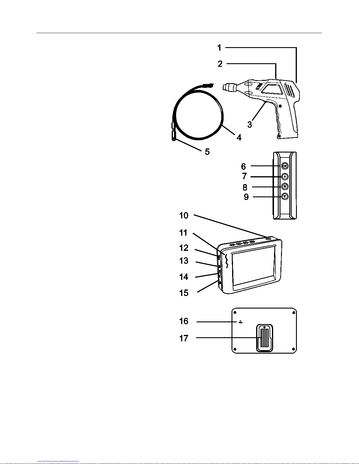
Description
1 Signal output
2 Power Indicator
3 Power On/Off, Dimmer
4 Flexible tube
5 Camera head and LED’s
6 OK
7 Up arrow, video or jpg
8 Menu
9 Down arrow
10 Power On/Off
11 Power Indicator
12 USB Socket
13 Video output
14 SD card socket
15 Power supply socket
16 Reset
17 Signal input
Page 4
BR200-BR250-en-GB_v7.5 4/17
4
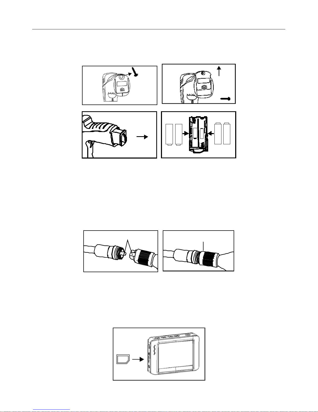
Installation
Install the batteries into the instrument body, charge the monitor battery, connect the camera and
flexible tube to the body, and insert the micro SD card. Install any accessory as needed.
Battery Installation
Connect Monitor Power
The monitor has a rechargeable battery. Plug in the AC adaptor and connect the cable to the
DC5V socket on the monitor. The power indicator will light in red (or the battery capacity icon on
LCD of monitor will blink, indicating that it is charging - and will turn off after a full charge)
Connect the camera and flexible tube
Connect the camera tube to the instrument body; ensure that the keyed ends are properly aligned.
Once aligned, tighten the knurled knob to hold the connection firmly in place.
Warning. Permanent damage to the flex tube and loss of operation will occur if the flex
tube is subjected to narrow radius or sharp angle bends.
Inserting the micro SD card
Insert card with arrow pointing toward slot. Gently apply pressure until card locks into the spring
loaded slot. To remove from unit, gently push the card inward and then release to eject it from the
card slot. Please use Class 4 (or higher) TF Flash memory card.
Page 5

BR200-BR250-en-GB_v7.5 4/17
5
Installing the accessory tools (BR200)
The included accessories (mirror, hook and magnet) all attach to the camera in the same manner.
Refer to the diagrams below:
Installing the accessory tools (BR250)
Hook the attachment into the hole in the head and then slide the rubber sleeve over the
attachment shaft
Attaching the Monitor to the instrument body
Connect the USB Cable
Use the USB cable to connect the monitor to a PC. The USB online icon will appear on the
PC. Open My Computer on the PC, and locate the Mobile Disk. The Mobile disk can be
used and accessed in the same manner as any external hard drive.
Video Output
Insert the video cable into the VIDEO OUT socket on the monitor. Insert the other end of the
cable into the VIDEO IN jack of a TV or other monitor. The LCD Monitor will output a high
quality video image.
Installing the Magneti c bracket
The magnetic bracket slides onto the rear of the monitor for convenient placement and
viewing.
Page 6

BR200-BR250-en-GB_v7.5 4/17
6
Operation
Basic Operation
1. Turn the ON/OFF dial switch to power the camera. The power indicator will switch on. The
switch then acts as a dimmer for the two LEDs on the imager head of the camera.
2. Press and hold the monitor power switch for at least 2 seconds and the power indicator will
illuminate green and a Welcome screen will appear.
3. The real time image will then appear on the display LCD monitor.
Note. If the picture does not properly syncronize or has poor color, check that the Video
System Settings are set to “NTSC”, not to ‘PAL” . This should fix the condition..
4. Use the up arrow to select video
or photo mode.
5. Turn the ON/OFF dial to adjust the LED light intensity as desired.
6. The tube can be easily maneuvered into position. The tube can be bent into the shape of the
area to be examined.
7. Use the supplied accessories to help retrieve small items.
LCD Reset
If the BR200/BR250 LCD Monitor will not power ON, or if it powers OFF during use, follow the steps
below to perform a Power Reset:
1. Un-dock the LCD module from the BR200/BR250 pistol-grip base unit.
2. Connect the AC adapter to the LCD module and to the appropriate AC power source.
3. Locate the Power Reset port on the reverse side of the LCD module (labeled Reset).
4. Using a non-metallic object, momentarily press the Power Reset button for a period of 2-to-5
seconds and then release.
5. Leaving the AC adapter connected to the LCD module, attempt to power the unit ON.
6. If the unit powers ON, allow it to fully re-charge (up to 2 hours) before removing the AC
adapter. If the LCD unit does not power ON, repeat steps 1 through 6.
If, after two attempts to reset the LCD, the unit still does not power ON, contact Technical Support.
Taking a Picture
In Photo mode, press OK to take a picture. The photo will automatically save to the SD
card.
Recording a Video
In Real-Time Monitoring (video) mode, press OK to begin recording; refer to the following diagram
for display icon definitions:
1. Battery capacity
2. Function icon (video/photo)
3. Recording in progress
4. ZOOM level
5. Current Date and Time
6. REC Time remaining
7. SD card
Page 7

BR200-BR250-en-GB_v7.5 4/17
7
Viewing a Photo or Video
1. In the Real-Time Monitoring mode, press to display a list of
dated playback folders
2. Use the ▼▲keys to select the de si r ed f ol der.
3. Press OK to open the selected folder and view a list of photo or
video files.
4. Files are listed by time followed by (VID”) for photos or (VID) for
videos
5. Use the ▼▲keys to select a file.
6. Press OK to display the selected photo or video.
For video files:
Press OK to pause while playing.
Press again to resume.
▲ Fast Forwards the video
▼ Rewinds the video
Press to stop video
7. Press to return to menu.
8. Press again to exit.
Note: Video automatically saves to file every 30 minutes. When the SD card is filled to capacity, the SD
card icon changes to ‘F’. No video will be recorded if the SD card is not inserted in the slot.
Delete a Single Video O r Photo
1. In the Real-Time Monitoring mode, press to display a list of dated
playback folders
2. Use the ▼▲keys to select the desired folder.
3. Press OK to open the selected folder and view a list of photo or
video files.
4. Files are listed by time followed by (VID”) for photos or (VID) for
videos
5. Use the ▼▲keys to select a file.
6. Press and HOLD the button, the display will show ‘DELETE
CURRENT FILE?’
7. Use the arrow keys to select YES or NO
8. Press OK to accept selection.
9. Press twice to exit the Delete screen.
Delete a File Folder
To delete a folder, use the same instructions for deleting a single video or photo. The only additional
concern is that if a folder is not empty it cannot be deleted. Delete all of the files in a folder before
deleting the folder. If the user attempts to delete a folder that is not empty, the following message will
appear: FOLDER NOT EMPTY
Video Display on a PC
Several methods are availa ble t o playback or to copy video files on a PC. When connected, the files will
become available as new driv es on t he PC .
1. SD card adaptor: Insert the SD card into the SD adaptor and then insert the adaptor into the PC
SD slot (if available)
2. USB adaptor: Insert the SD card into a USB adaptor and plug into a USB port.
3. USB cable. Connect the USB cable from the camera to the PC.
Page 8

BR200-BR250-en-GB_v7.5 4/17
8
Settings Mode
Press and hold for two seconds to enter the Settings Mode.
Language Settings
1. In Settings Mode, use the arrow keys to select SYSTEM SETTING (green icon).
2. Press OK to call up the SYSTEM icon list
3. Use the arrow keys to highlight the Language icon (globe)
4. Press OK and the Language icon list will appear (flags)
5. Use the arrow keys to highlight the desired language
6. Press OK to select the highlighted language and exit
Video System Settings
1. In Settings Mode, use the arrow keys to select SYSTEM SETTING (green icon).
2. Press OK to call up the SYSTEM icon list
3. Use the arrow keys to highlight the Video System icon (yellow)
4. Press OK and the Video format selections will appear (NTSC, PAL)
5. Use the arrow keys to highlight NTSC
6. Press OK to select the highlighted format and exit
Format and Erase Media
1. In Settings Mode, use the arrow keys to select SYSTEM SETTING (green icon).
2. Press OK to call up the SYSTEM icon list
3. Use the arrow keys to highlight the FORMAT icon (blue)
4. Press OK and the FORMAT selection screen will appear (YES, NO)
5. Use the arrow keys to highlight the desired response
6. Press OK to accept the selection and exit
Restoring Factory Default Settings
1. In Settings Mode, use the arrow keys to select SYSTEM SETTING (green icon).
2. Press OK to call up the SYSTEM icon list
3. Use the arrow keys to highlight the DEFAULT icon (red)
4. Press OK and the DEFAULT selection screen will appear (YES, NO)
5. Use the arrow keys to highlight the desired response
6. Press OK to accept the selection and exit
View Version
1. In Settings Mode, use the arrow keys to select SYSTEM SETTING (green icon).
2. Press OK to call up the SYSTEM icon list
3. Use the arrow keys to highlight the VERSION icon (green)
4. Press OK to view the version
5. Press OK again to exit
Frame Rate Setting
1. In Settings Mode, use the arrow keys to select RECORDER SETTING (red icon).
2. Press OK to call up the RECORDER options
3. Use the arrow keys to highlight the FPS (frames per second) icon
4. Press OK to open the FPS parameter
5. Use the arrows to select the frame rate: 10, 15, 20, 25, or 30
6. Press OK to confirm
Page 9

BR200-BR250-en-GB_v7.5 4/17
9
Time Stamp ON OFF Setting
1. In Settings Mode, use the arrow keys to select RECORDER SETTING (red icon).
2. Press OK to call up the RECORDER options
3. Use the arrow keys to highlight the Time Stamp icon (purple)
4. Press OK to open the parameter
5. Use the arrows to select ON or OFF
6. Press OK to confirm
Date/Time Setting
1. In Settings Mode, use the arrow keys to select DATE-TIME SETTING (yellow icon).
2. Press OK to call up Date and Time Settings window
3. Use OK to tab through the fields
4. Use the arrow keys to change a field setting
5. Press the button to exit
Battery Replacement
Never dispose of used batteries or rechargeable batteries in household waste.
As consumers, users are legally required to take used batteries to appropriate collection
sites, the retail store where the batteries were purchased, or wherever batteries are sold.
Disposal: Do not dispose of this instrument in household waste. The user is obligated to
take end-of-life devices to a designated collection point for the disposal of electrical and
electronic equipment.
Page 10

BR200-BR250-en-GB_v7.5 4/17
10
Specifications
CAMERA
Imaging Sensor CMOS
Total Pixels (NTSC) BR200: 712 x 486; BR250: 640 x 480
Horizontal View Angle BR200: 50 degrees
BR250: 45 degrees
Transmission Frequency 2468MHz
Focus point BR200: 20cm (8”), BR250: 10cm (4”)
Minimum Illumination 0 Lux
Modulation Type FM
Bandwidth 18MHz
Power Supply 4 x AA batteries
Unobstructed Effective Range 10m
Waterproof Capacity IP67 (imager head only)
Dimensions (W D H) 186 x 145 x 41(mm) (Exclude Flexible Tube)
Weight (approx) BR200: 530g
BR250: 450g
Camera head Diameter BR200: 17mm (0.67”)
BR250: 9mm (0.36”)
Operating Temperature -10°C~+50°C
+14°F~+122°F
MONITOR
LCD Screen Type 3.5” TFT-LCD
Effective Pixels 320 (R.G.B.) x 240
Video System PAL/NTSC
Transmission Frequency 2468MHz (CH 4)
Exterior Supply Voltage 5VDC
Consumption Current (Max.) 500mA
Charge Time 3 hours
Work Time 2 hours
Video Output Level 0.9-1.3VP-P@75Ώ
Receiving Sensitivity ≤-85dBm
Dimensions (W x D x H) 100 x 70 x 25(mm)
Weight (Approx) 140g
Operating Temperature -10°C~+50°C
+14°F~+122°F
Operating Humidity (Max.) 15~85%RH
FCC Information
This device complies with part 15 of the FCC rules.
BR250/200: FCC-ID TW5GB8802-GB8803
Operation is subjec
t to the following two conditions:
1. This device may not cause harmful interference
2. This device must accept any interference received, including interference that may cause
undesired operation.
Copyright © 2014-2017 FLIR Systems, Inc.
All rights reserved including the right of reproduction in whole or in part in any form
ISO-9001 Certified
Page 11

ALPINE
COMPONENTS
Postal Address
Alpine Components Ltd
Innovation Centre, Highfield Drive
Churchfields
St. Leonards-on-
Sea
TN38 9UH
United Kingdom
Telephone
01424 858118
Website Address
www.alpine-
components.co.uk
"Alpine Components" is the abbreviated trading name for "Alpine Components Limited"
The company has been trading since 1991 and was incorporated on 13/11/2006 in the United Kingdom
Company Registration Number: 05996485
VAT Number: GB583598190
 Loading...