

Page 1
User's Guide
IR Thermometer Printer / Datalogger
Model 42580
Datalogging/Printing IR Thermometer
#5: LOGGING
01:16-03 11:19:59
76.6°F
02:
---.-°F
03:
---.-°F
05-16-03 11:20:00
42580
Test Equipment Depot - 800.517.8431 - 99 Washington Street Melrose, MA 02176
FAX 781.665.0780 - TestEquipmentDepot.com
Page 2

Introduction
Congratulations on your purchase of the Extech 42580 IR Thermometer PrinterDatalogger. This device measures temperature using a non-contact IR sensor. The
Datalogger feature stores up to 100 readings in each set (4 sets total) for a total of 400
readings. The Printer provides a hard copy of individual readings or entire data sets. PC
software permits downloading of data for further analysis. Careful use of this meter will
provide years of reliable service.
Specifications
Display Backlit Multi-function LCD
IR Measurement ranges -40 to 932
Accuracy: -4 to 932ºF (-20 to 500
o
F (-40 to 500oC)
o
C); ±2% of reading or ±4ºF/2ºC
(whichever is greater)
o
-40 to -4ºF (-40 to 20
Resolution 0.1
Repeatability ±1
o
for displays <100o, otherwise 1o
o
C); ±6ºF/3ºC
IR distance ratio 8:1
Response time 0.2 seconds
Emissivity Adjustable from 0.3 to 1.0
Datalogger memory 400 readings (0-99 readings in each of 4 sets)
Over range indication "-------" appears on the LCD
Printer 38mm Printer
PC Interface RS-232C (TTL level)
Low battery indication Battery symbol appears on the LCD
Power supply Four (4) 1.5V ‘AA” batteries or optional 6V (1000mA) adapter
Operating current 500mA (printing), 6mA (IR active), 2mA (IR standby)
Auto Power OFF After 10 seconds
Operating Temperature 32 to 122
o
F (0 to 50oC)
Operating Humidity 90% Relative Humidity max.
Dimensions/Weight 8.2 x 2.8 x 2.1” (208 x 70 x 53mm) / 9.2 oz. (260g) with battery
2
Model 42580 Version 2.2 11/03
Page 3
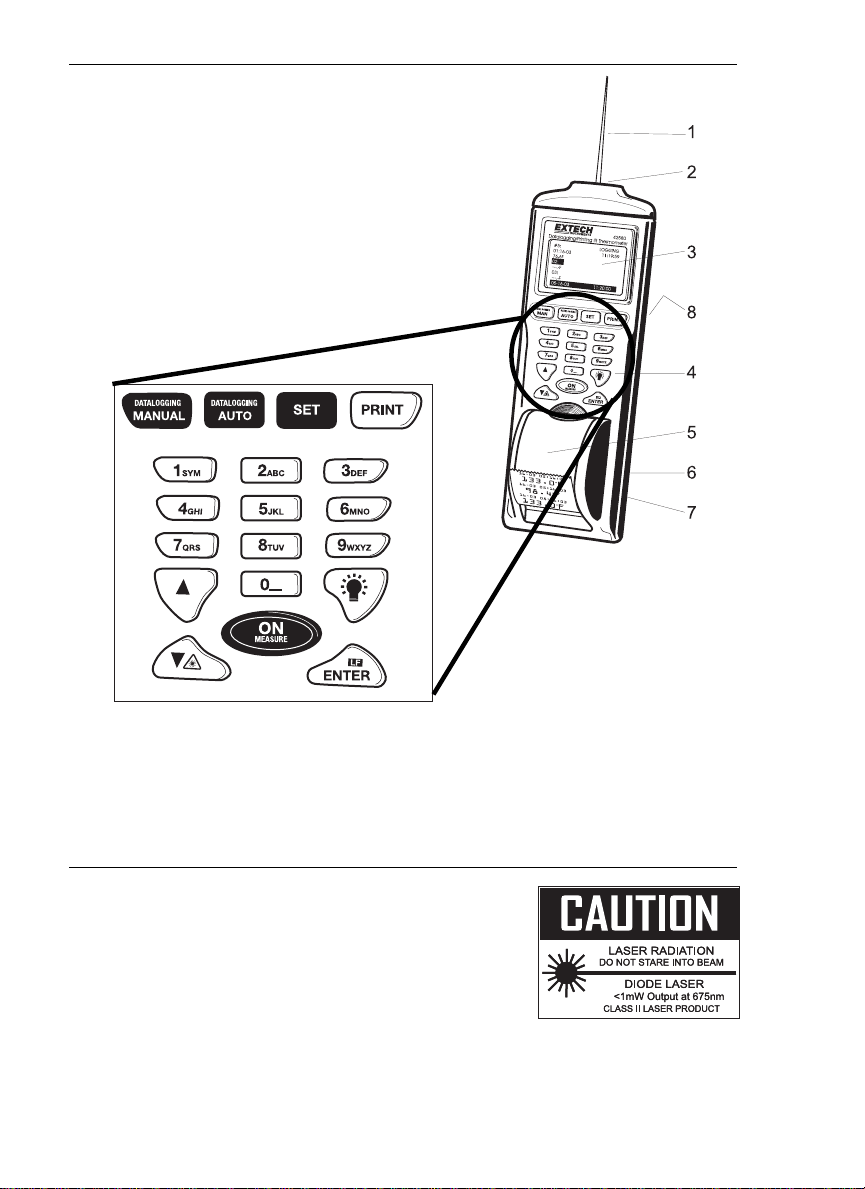
Meter Description
1. Laser pointer beam
2. Non-contact temperature sensor
3. LCD Display
4. Push-button keypad
5. Printer paper and paper compartment
6. RS-232c TTL output jack
7. AC Adapter jack
8. Battery compartment (rear)
Safety
• Use caution when the laser pointer beam is on
• Do not point the beam toward anyone's eye or allow the
beam to strike the eye from a reflective surface
• Do not use the laser near explosive gases or in other
potentially explosive areas
Test Equipment Depot - 800.517.8431 - 99 Washington Street Melrose, MA 02176
FAX 781.665.0780 - TestEquipmentDepot.com
3
Model 42580 Version 2.2 11/03
Page 4
Operation
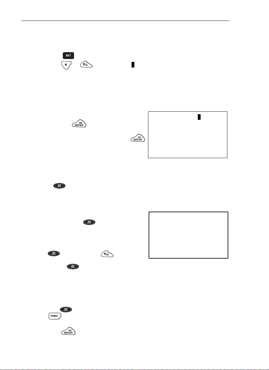
Setup
The Setup Screen provides access to the LCD Contrast, Printer Contrast, Emissivity
setting, Temperature Units and setting of the date and time.
1. Press the button to access the setup screen.
2. Press the or key to move the 1 cursor to the desired position.
3. The programmable parameters are as follows:
• LCD Cont: Adjust the LCD contrast (0-5) using the numeric keypad.
• Prn Cont: Adjust the print contrast (0-9) using the numeric keypad.
• Emi. Rate: Adjust the emissivity (0.0 to 1.0); Set to 0.95 if not sure of emissivity
value for the surface under test.
• Unit: Select temperature units (°C or°F)
using the button.
• Date: Select date format MM:DD:YY,
DD:MM:YY, or YY:MM:DD using the
button.
• Set Clock: Set the current month, day,
year, hour, minute, and second. Use the
arrow keys to move from digit to digit.
Use the numeric buttons to change the
number.
4. Press to exit setup mode.
IR Measurements
1. Point the meter at the surface to be measured.
2. Press and Hold the button to measure
the temperature.
3. The red laser pointer identifies the spot being
measured. Aim the laser pointer at the center
of the surface to be measured. While pressing
the button, press the button to
enable or disable the pointer.
4. Release the button and the last
measured value will remain in the display for
approximately 8 seconds.
LCD Cont: 1
Prn Cont: 2
Emi. Rate: 0.95
Unit: F
Date: MM:DD:YY
Set Clock:
MM:DD:YY hh:mm:ss
SETUP Screen
79.2oF
06:25:03 13:55:55
IR Measurement Display
Printing IR Measurements
1. Perform the IR Measurement procedure.
2. After the button has been released and before 8 seconds have passed, press
the button.
3. The printer will print the temperature, date and time.
4. Press the button to feed the paper.
4
Model 42580 Version 2.2 11/03
Page 5

Field of View
The meter’s field of view is 8:1, meaning that if the meter is 8 inches from the target, the
diameter of the object under test must be at least 1 inch. Other distances are shown below
in the field of view diagram. Refer to the chart printed on the meter for more information.
4”
Diameter of Spot
0.5”
8”
Distance to Object
1”
16”
2”
4”
Laser Beam
0.63”
Sensor Beam
32”
Measurement Notes
1. The object under test should be larger than the spot (target) size calculated by the field
of view diagram (see diagram on previous page or on side of the meter).
2. If the surface of the object under test is covered with frost, oil, grime, etc., clean before
taking measurements.
3. If an object's surface is highly reflective apply masking tape or flat black paint before
measuring.
4. The meter may not make accurate measurements through transparent surfaces such
as glass.
5. Steam, dust, smoke, etc. will affect measurements.
6. The meter compensates for deviations in ambient temperature. It can, however, take
up to 30 minutes for the meter to adjust to extremely wide ambient temperature
changes.
7. To find a hot spot, aim the meter outside the area of interest then scan across (in an up
and down motion) until the hot spot is located.
Datalogging
Overview
The Model 42580 has two datalogging modes of operation, Manual Datalogging and
Automatic Datalogging. Each has 4 sets. Each set can hold 99 readings. Data sets can be
printed in their entirety.:
• Manual Datalogging: Up to 99 readings can be stored in Sets 1, 2, 3, & 4. Data storage
is performed manually by pressing followed by for each data point
(detailed in subsequent sections).
• Automatic Datalogging: Up to 99 readings can be stored in Sets 5, 6, 7, & 8. In
Automatic Datalogging mode, the user programs the recording start & stop date & time,
and the recording interval. Automatic Datalogging.
5
Model 42580 Version 2.2 11/03
Page 6

Manual Data Storage Mode
The Model 42580 can store 99 readings in each of 4 sets numbered #1 through #4. The
function of the buttons in the Manual Datalogging mode are:
Opens the manual data storage mode, Opens a set and clears the data.
Selects the set # for recording or viewing.
Prints the stored records in a set.
Scroll up or down through the records in a set.
Stores the temperature reading.
1 to Z Alpha-numeric label entry (9 buttons).
1. Press the button to enter the manual data
storage mode. A cursor (11111111) will appear
next to the selected set# with the label (if stored).
2. Press the button to scroll through and select
one of the four sets.
3. If data is stored in the set, the label or the date and
time will appear next to the record number.
4. Press again to open the selected set.
5. The Set Screen will open with the cursor on the first
record number that does not contain any data. Data
can now be viewed, printed or new data can be
saved to the set.
6. Press the button a third time to EXIT the
Manual logging mode.
#1 User Defined Label
01: 07-11 13:55:25
02: 07-11 14:05:03
03:
04:
05:
Manual logging Screen
#2
01: 07-14 13:55:25
79.9
02:
----. -- oF
03:
----. --
07-14-03 10:11:51
Manual logging Open Set Screen
o
F
o
F
Storing Data
1. Point the meter at the surface to be measured.
2. Press and Hold the button until a reading appears on the display in a box.
3. Release the button and press the button.
4. For each set up to 99 readings can be stored.
Viewing Data
Press the buttons to scroll through and view the stored data.
Printing Data
Press the button and the display will respond with Print? . Press the button
a second time to confirm the print request. The printer will print all the records from record
01 to the last record that contains data.
Erasing Data
Press and HOLD the button for at least three seconds and the recorded data will be
erased. To clear the date and time (or stored labels) Press and HOLD the button
for at least three second while in the Manual logging Mode Main Screen.
Test Equipment Depot - 800.517.8431 - 99 Washington Street Melrose, MA 02176
FAX 781.665.0780 - TestEquipmentDepot.com
Page 7

Automatic Datalogging Mode
In the Auto Datalogging mode the Model 42580 can automatically measure and store 99
readings at a programmed sample rate. Four separate sets, numbered 5 through 8, can
hold 99 readings each. The function of the buttons in the LOG mode are:
Opens the automatic data storage mode, opens a set and clears the data
Selects the set # for recording or viewing.
Prints the stored records in a set.
Scroll up or down through the records in a set.
Stores Start time, Stop time and Log rate.
0… Stops a logging session
1 to Z Alpha-numeric label entry (9 buttons).
Selecting the Datalog Set
1. Press the button. A data set Configure
Screen will appear.
2. There are four sets available, numbered 5
through 8 (upper left hand corner).
3. Press the button to scroll through and
select one of the four sets.
Configuring the Datalogger
1. After selecting a set, use the
buttons to move through the fields and use the
alpha-numeric buttons to edit the parameters in
the fields shown in the diagram.
2. The programmable fields are:.
• Begin: Date when recording is to begin.
• End: Date when recording will end.
• Start: Time when recording will begin.
• Suspend: Time when recording will end.
• Rate: Interval of time between each reading (1 to 7200 seconds)
• Start now? Press while YES is highlighted to start recording at the date
and time programmed above.
Note that the datalogger will automatically record from the START time to the
SUSPEND time every day from the BEGIN day to the END day
#6
Begin: 06-25-03
End: 06-25-03
Start: 13:55:00
Suspend: 14:00:00
Rate: 20
Start now? Yes
Datalog Configure Screen
7
Model 42580 Version 2.2 11/03
Page 8

Recording Data in the Automatic Datalogging Mode
1. After preparing a data set and configuring the datalogger, place the meter in position to
take readings (tripod mount is provided on rear of instrument).
2. Recording will begin on the date and time
programmed at the BEGIN and START lines in
the ‘Configure Screen’.
3. The Datalogger will record everyday from the
START time to the SUSPEND time. The last
day is the date programmed in the END line.
4. To stop the datalogger before the programmed
#5
01:
02:
79.2
79.3
o
F
o
F
SUSPEND time, press the 0 button.
5. To view the data recorded, press the
Mode Measure Screen
key twice. The data will be listed as shown in
the ‘Measure Screen’ diagram at right.
6. Use the numeric keys to move quickly through the data list. Pressing the ‘1’ key calls
up data point ‘01’; pressing the ‘2’ key calls up data point ‘21’, and so on.
7. To print data from the list, press the button. Press again when the
PRINT? display appears.
8. To clear (erase) the recorded data, press and hold the button for 2-3 seconds
with the data list shown on the display.
Backlight button
Press to activate the meter’s display backlight.
Editing Names and Labels:
The 42580 has the capability of storing a 14 character label with each set or record.
The label can be entered either through the numeric keypad or the optional software. (See
the software section for instructions on entering labels via the software)
To create a label, with the (11111111) cursor next to the set# or record, press to
switch to a single character cursor (1).
Press any button repeatedly to scroll through the available characters.
If the button is not active for a short period of time the character selected will be written to
the screen.
Press the or buttons to scroll forward or backwards.
For example, to select the letter ‘T’, press the ‘8’ key five times. The meter will move the
cursor to the next digit place automatically. Note that the ‘1’ button has special characters
in addition to the numeral ‘1’. The ‘0’ key has a blank space in addition to the numeral ‘0’.
Press to store the name.
8
Model 42580 Version 2.2 11/03
Page 9

Maintenance
Cleaning
Wipe instrument with damp cloth as needed. Do not apply solvents or abrasives to the
meter. Store in a cool dry place with the batteries removed.
Battery Replacement
When the batteries weaken, the LCD display will dim or go completely blank. To replace
the batteries, open the rear battery compartment and insert four (4) new 1.5V ‘AA’ batteries
with correct polarity position.
Paper roll replacement
When the paper roll is depleted, flip up the
paper compartment, drop in a new roll, and
feed the paper using the LF button. New paper
rolls are available through Extech instruments
and Extech distributors.
Emissivity Considerations
The amount of IR energy emitted by an object is proportional to an object's temperature and
its ability to emit energy. This ability is known as emissivity and is based upon the material of
the object and its surface finish. Emissivity values range from 0.1 for a very reflective object
to 1.00 for a flat black finish. The 42580 senses IR energy and calculates the temperature
based upon the amount of IR energy it receives using a factory default emissivity setting of
0.95 (this setting covers 90% of applications).
Most organic materials and painted or oxidized surfaces have an emissivity factor of 0.95.
Inaccurate readings will result from measuring shiny or polished metal surfaces which have
emissivity factors other than 0.95. To compensate for polished/shiny surfaces, cover the
surface with masking tape or flat black paint. Allow time, before measuring, for the tape to
reach the same temperature as the material underneath it.
Emissivity Factors for Common Materials
Material under test Emissivity Material under test Emissivity
Asphalt 0.90 to 0.98 Cloth (black) 0.98
Concrete 0.94 Skin (human) 0.98
Cement 0.96 Lather 0.75 to 0.80
Sand 0.90 Charcoal (powder) 0.96
Soil 0.92 to 0.96 Lacquer 0.80 to 0.95
Water 0.92 to 0.96 Lacquer (matt) 0.97
Ice 0.96 to 0.98 Rubber (black) 0.94
Snow 0.83 Plastic 0.85 to 0.95
Glass 0.90 to 0.95 Timber 0.90
Ceramic 0.90 to 0.94 Paper 0.70 to 0.94
Marble 0.94 Chromium Oxides 0.81
Plaster 0.80 to 0.90 Copper Oxides 0.78
Mortar 0.89 to 0.91 Iron Oxides 0.78 to 0.82
Brick 0.93 to 0.96 Textiles 0.90
Test Equipment Depot - 800.517.8431 - 99 Washington Street Melrose, MA 02176
FAX 781.665.0780 - TestEquipmentDepot.com
Page 10

Software
System Requirements
• Hardware Requirements: 486 PC or better with COM 1 and COM 2 Serial ports
• Operating System Compatibility: Windows
Hardware Connection
The IR Thermometer connects to a PC with the supplied DB-9 to 3.5mm mini-plug (mono)
interface cable. The DB-9 end connects to the PC serial com port. The mini-plug end
connects to the IR Thermometer.
Software Installation
The instructions on how to install the optional software are printed on the Software CD
label. After reading the label’s directions, load the software CD in the PC CD-ROM drive.
Starting the Software
Run the program by opening the program named “IR Meter”.
This program is located in the programs folder of the Windows Start Menu.
Once the program is running, the Main Software screen will appear.
TM
95/98/NT/2000/XP
10
Model 42580 Version 2.2 11/03
Page 11

Software Operation
When the program is started the meter and PC begin communicating. The main software
screen appears.
Buttons:
Clear
File Save
Load File
Print Set Selector Download Upload
Entering Descriptions for Manual Recordings
The 42580 has the capability of storing a 14 character label with each record to help in
organizing the data collected. The label can be entered either before or after the readings
are made. If no label is entered the default description is the Date and Time Stamp of the
reading. (Please note that labels for automatic readings cannot be changed and will always
be the Date and Time Stamp)
To enter labels for uploading
1. On the toolbar click on
the clear button
2. Click on the set selector
drop down screen and
select the desired set (1
to 4 for manual)
3. Enter desired labels
4. Click on upload button.
Data transfer will begin.
The meter will display
PC MODE in the screen
until transfer is
completed.
11
Model 42580 Version 2.2 11/03
Page 12

Downloading Sets from the Meter
Sets previously recorded by the IR Meter can be downloaded individually or as a group.
With the meter connected to the PC and the software running
To download an individual set:
1. On the toolbar Click on the
set selector drop down
screen
2. Click on a set
3. Click on the download
button
To download all sets
simultaneously:
1. On the Menu Bar Click on
Command
2. Click on Download All Sets
Data will then transfer from the meter to the PC
Manual Readings with user defined labels Auto Logging with Date and Time Stamp
12
Model 42580 Version 2.2 11/03
Page 13

Save File
The SAVE FILE icon is
the second icon on the
left (floppy disk symbol).
Click on this icon to
save recorded data as a
text file. When clicked,
the PC will prompt for a
filename and location.
Once saved, this file can
be opened in other
programs such as
spreadsheets, word
processors, and
databases.
Load File
The OPEN FILE icon is
located third from left.
Double Click to open a
file that has already
been saved. Please note
that in order to view, the
file must be viewed in
the same set location
(i.e. If a file was
recorded as Set 2 it can
only be viewed with Set
2 selected in the set
selector drop down
menu.)
Erase Data
The ERASE icon is the first icon on the left. Click to clear data from the screen.
Print
The PRINT icon is
the fourth icon from
the left. Click to print.
When prompted,
enter the desired
set(s) and click OK
to begin printing.
Test Equipment Depot - 800.517.8431 - 99 Washington Street Melrose, MA 02176
13
Model 42580 Version 2.2 11/03
FAX 781.665.0780 - TestEquipmentDepot.com
 Loading...