

Page 1

INSTRUCTION MANUAL
Model 421508
Dual Input, 3-Display Handheld Thermometer
• Accepts J, K, T, E, R, S, & N thermocouples
• Backlit Electro-luminescent LCD Display
• T1 / T2 / T1 – T2 displays
• MIN / MAX / AVG Record/Recall
• Selectable temperature units (C/F)
• Data Hold, Relative Mode, Elapsed Timer
• Bi-directional RS-232 PC Interface
Introduction
Congratulations on your purchase of Extech’s Dual Input, 3-Display, Hand-Held Digital
Thermometer. This portable digital thermometer is designed to use external K / J / T / E / R
/ S / N type thermocouples (K-type supplied). Temperature indication follows Reference
Temperature/Voltage Tables (N.I.S.T. Monograph 175 Revised to ITS-90). This
professional meter, with proper care, will provide years of safe reliable service.
Page 1 Model 421508 Version 1.0 October 2002
Page 2
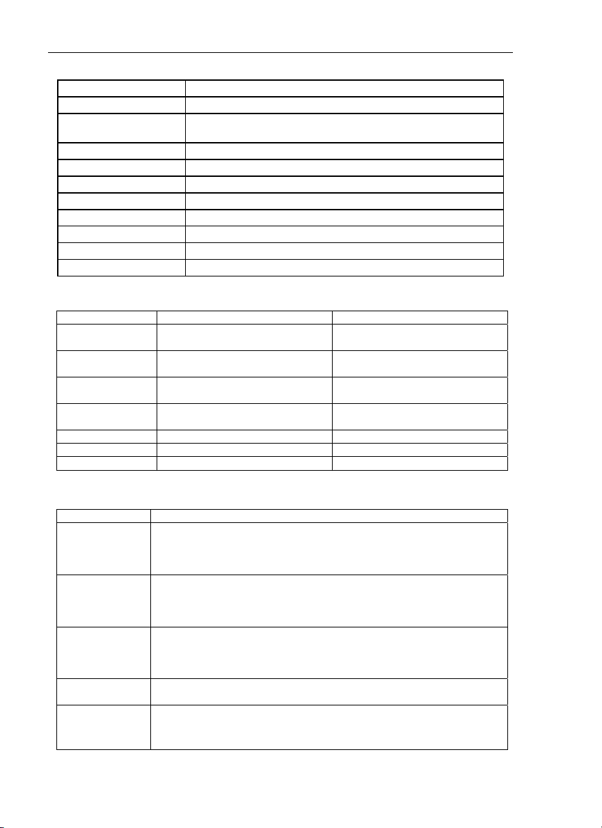
Specifications
General Specifications
Display 5-digit (9999.9), 3-Display, LCD with EL Backlighting
Water resistant housing Gasket protected front panel
Input Protection 24VDC or 24VAC rms maximum input on any combination of
inputs. Max voltage between T1 and T2 inputs is 1V
Reading rate One reading per second
Input connectors Accepts standard sub-miniature thermocouple connectors
Operating conditions 32 to 122oF (0 to 50oC); less than 80% RH
Storage conditions -4 to 140oF (-20 to 60oC); less than 70% RH
Dimensions / Weight 7.5 x 3.6 x 2.1” (192 x 91 x 52.5mm); 11.7oz. (365g)
Power Supply 9V battery
Auto Power off Meter automatically turns off after 30 minutes of inactivity
Battery life 100 hours typical
Range Specifications
Thermocouple Range Resolution
K type -328 to 2501oF (-200 to 1372oC) 0.1oF (0.1oC) from 0 to 700oF,
J type -346 to 1922oF (-210 to 1050oC) 0.1oF (0.1oC) from 0 to 500oF,
T type -328 to 752oF (-200 to 400oC) 0.1oF (0.1oC) from 0 to 600oF,
E type -346 to 1454oF (-210 to 790oC) 0.1oF (0.1oC) from 0 to 450oF,
o
F all other ranges
0.2
o
F all other ranges
0.2
o
F all other ranges
0.2
o
F all other ranges
0.2
R type 32 to 3212oF (0 to 1767oC) 1oF (1oC)
S type 32 to 3212oF (0 to 1767oC) 1oF (1oC)
N type -58 to 2372oF (-50 to 1300oC) 0.2oF (0.1oC)
Accuracy Specifications
Thermocouple Accuracy
K, J, T, E types ±(0.05% rdg + 0.6oF) -58oF to 2498oF
±(0.05% rdg + 1.4
±(0.05% rdg + 0.3
±(0.05% rdg + 0.7
N type ±(0.05% rdg + 1.4oF) -58oF to 32oF
±(0.05% rdg + 0.6
±(0.05% rdg + 0.7
±(0.05% rdg + 0.3
R, S types ±(0.05% rdg + 0.6oF) -58oF to 2498oF
±(0.05% rdg + 1.4
±(0.05% rdg + 0.3
±(0.05% rdg + 0.7
Temperature
Coefficient
Supplied
Thermocouples
0.1 multiplied by the accuracy per oC from 0oC to 18oC and 28oC to
o
C (32oF to 64oF and 82oF to 122oF)
50
4', type K (with teflon insulation) Max insulation temp: 500oF (260oC)
Accuracy: ± 4
32 to 1472
o
F) -58oF to 346oF
o
C) -50oC to 1370oC
o
C) -50oF to -210oC
o
F) 32oF to 2372oF
o
C) -50oC to 0oC
o
C) 0oF to 1300oC
o
F) -58oF to 346oF
o
C) -50oC to 1370oC
o
C) -50oF to -210oC
o
F (2.2oC) or ± 0.75% of rdg (whichever is greater) from
o
F (0 to 800oC)
Page 2 Model 421508 Version 1.0 October 2002
Page 3

Safety Information
Please read the safety and operational instructions before using this device.
WARNING
To avoid electrical shock, do not use this instrument when working near voltages over 24V
AC/DC.
WARNING
To avoid damage or burns, do not make temperature measurement in microwave ovens.
CAUTION
Repeated flexing can break the thermocouple leads. To prolong lead life, avoid sharp
bends in the leads, especially near the connector.
This symbol on the instrument indicates that the operator must refer to an
!
explanation in this manual.
Meter Description
1. Thermocouple inputs
1
2
2. Optical PC Interface
3. LCD Display
4. Keypad
5. Rubber meter holster
6. Battery compartment and
tilt stand on rear
3
4
5
6
Page 3 Model 421508 Version 1.0 October 2002
Page 4

Meter Operation
Power Key
The Power key (red key) turns the thermometer ON or OFF. Note that in the MIN/MAX
record mode the thermometer cannot be powered off. Be sure to exit the MIN/MAX record
mode before powering off.
°C/°F Key
Readings can be displayed in degrees Celsius (°C) or degrees Fahrenheit (°F). Note that
the meter remembers the unit of measure when it is turned off. Press the °C/°F key to
change the temperature units. The C/F key is also the zero (0) key and the minus (-) key
for negative number entry (explained later in the ‘SET Key’ section).
HOLD Key (Main Display only)
Press the HOLD key to enter the Data Hold mode, the "HOLD" annunciator will display.
When HOLD is selected, the thermometer freezes the reading on the main display (the
main display is the center LCD line with the largest digits). Press the HOLD key again to
return to the normal measurement mode. In the MIN/MAX recording mode, use the HOLD
key as a pause/resume recording control. The HOLD key doubles as the ENTER key for
programming purposes.
T1 T2/T1-T2 Key - Main Display Input Selection
Note that this key doubles as the numeric ‘1’ key. Press this key to select which
thermocouple input configuration is represented on the main display; ‘T1’ will display for
thermocouple input 1, ‘T2’ for thermocouple 2, or ‘T1-T2’ for the difference between the
two thermocouple measurements.
Type Key - Thermocouple Type for T1
Note that this key doubles as the numeric ‘2’ key. Use the TYPE key to select the
thermocouple type (K, J, T, E, R, S, or N) that is connected to the T1 input. The
thermocouple type is indicated on the left side of the LCD. When the thermometer is turned
on, it remembers the type used when the thermometer was last turned off.
MIN MAX Key
Note: Auto Power OFF and several keys (C/F, REL, SET, HI/LO, TYPE, and T1 T2 T1-T2)
are defeated in this mode
Press MIN MAX to enter the MIN MAX recording mode; the meter will begin keeping track
of the highest (MAX), lowest (MIN), and Average (AVG) readings. There are four displays
(listed below) for this mode. Use the MIN MAX key to scroll through all four.
a. When the RECORD icon is on the display (top), the meter is displaying measurements
normally while it is recording.
b. With the RECORD MAX icon on the display, the meter continues taking measurements
but the main display shows only the highest (MAX) reading recorded. The Elapsed
Time (in hours, minutes, and seconds) is shown in the lower right LCD field. The Timer
shows when the MAX reading was taken.
c. With the RECORD MIN icon on the display, the main display shows only the lowest
reading recorded. The Time of the MIN reading is shown in the lower right LCD field.
d. With the RECORD AVG icon on the display, the main display shows only the average
of all the readings recorded. Note that the averaging limit is 22 hours. After 22 hours,
the last average reading display is held on the LCD.
The meter emits a tone when a new minimum or maximum value is recorded. Use the
HOLD key to pause recording (all values are then held). Press HOLD again to resume
recording. To exit the MIN MAX mode press and hold the MIN MAX key until the RECORD
icon switches off.
Page 4 Model 421508 Version 1.0 October 2002
Page 5

REL Relative key
Press the REL key to enter the Relative mode. The meter will now store the displayed
reading (main display) as a reference value and display ‘REL’. All subsequent readings will
now display less the stored reference value. Press the REL key again to exit the relative
mode. Note that the Relative reference value can also be entered manually (see the ‘SET
Key’ paragraph below). The Relative mode is also a useful zeroing function. Note that the
reference value cannot exceed ±3000.0 counts.
Hi/Lo LIMITS key (Main display only)
Press the Hi/Lo LIMITS key to enter the Hi/Lo Limits comparative mode ("LIMIT" will be
displayed on the LCD). When the measured temperature is higher than the High Limit (or
lower than the Low Limit), the alarm beeper emits a tone and "Hi" “or “Lo” is displayed.
Note: The tones for High and Low Alarms are different; the High Alarm tone is continuous
while the Low Alarm tone is pulsed. Use the SET key to program the temperature limits as
explained in the next paragraph. Press the Hi/Lo LIMIT key again to exit the Hi/Lo LIMIT
mode. In this mode the automatic power-off feature is disabled along with the following
keys: REL, HOLD, & MIN MAX.
SET Key (Setting Relative Value, High / Low Alarm Limits, and the Timer)
Follow the steps a. through c. below for programming any or all of the SET parameters.
Use the overlay second-function keys (- 0 through 9 and ENTER) when entering numbers.
For negative numbers, press the (- 0) key after
key is used to enter the programmed data and queue the next SET parameter.
a. Setting the Relative Mode reference value
Press the SET key to enter the Relative value setting mode. When in this mode, dashes
are displayed on the main display. Manually program the desired value via the numeric
keys. Press the ENTER key to store the relative value and move to the High / Low Limit
setting mode.
b. Setting the High and Low Alarm Limits
In the High Limit setting mode all dashes are initially displayed on the main display. Use
the numeric keys to program the desired High Limit value and then press ENTER to store
the value. Perform the same steps for setting the Low Limit value. The Elapsed Timer SET
mode is then queued.
c. Setting the Elapsed Timer
Use the numeric keys to enter the Hours, Minutes, and Seconds for the Timer. Press
ENTER to store this value and exit the SET mode.
T1/T2 T1-T2 (Second Display Input Selection)
This key doubles as the numeric ‘7’ key. Press this key to select which input is shown on
the secondary display (lower left display); T1 for thermocouple 1, T2 for thermocouple 2, or
T1-T2 to display the difference between the two thermocouples.
the number has been entered. The ENTER
Type Key - Thermocouple Type for T2 input (Second Display)
This key doubles as the numeric ‘8’ key. Use the TYPE key to select the thermocouple
type (K, J, T, E, R, S, or N) for the T2 input. The input type is shown on the left side of the
LCD in smaller digits than for the T1 input. When the thermometer is turned on, it
remembers the type in use when the thermometer was last turned off.
Backlight Button
The backlight button (bottom right) doubles as the numeric ‘9’ key. Press the backlight
button to toggle the backlighting on and off. The backlight will switch-off automatically after
60 seconds to conserve battery life.
Page 5 Model 421508 Version 1.0 October 2002
Page 6

RS-232 PC Interface
The Model 421508 Thermometer is supplied with a sophisticated Windows
package on disk. A communications cable (meter to PC) is also supplied. The disk
contains program files, software instructions, and communication protocol; refer to the disk
for details.
The program allows the user to operate the meter remotely and view the readings from all
three LCD fields on the PC monitor. The software also permits measurement data to be
stored as text files on a PC. The data files can then be exported to spreadsheet or other
programs for further manipulation (graphing, sorting, filing, etc.).
TM
software
Battery Replacement
Replace the battery when the low battery indication symbol appears on the upper left
corner of the display. To replace the battery, remove the two screws that secure the rear
battery compartment cover. Remove the old battery, install a new one, and replace cover
Calibration and Repair Services
Extech offers complete repair and calibration services for all of the products we sell. For
periodic calibration, NIST certification or repair of any Extech product, call customer
service for details on services available. Extech recommends that calibration be performed
on an annual basis to ensure calibration integrity.
Warranty
EXTECH INSTRUMENTS CORPORATION warrants this instrument to be free of defects in parts and workmanship for one
year from date of shipment (a six month limited warranty applies on sensors and cables). If it should become necessary to
return the instrument for service during or beyond the warranty period, contact the Customer Service Department at (781)
890-7440 ext. 210 for authorization or visit our website at www.extech.com (click on ‘Contact Extech’ and go to ‘Service
Department’ to request an RA number). A Return Authorization (RA) number must be issued before any product is returned
to Extech. The sender is responsible for shipping charges, freight, insurance and proper packaging to prevent damage in
transit. This warranty does not apply to defects resulting from action of the user such as misuse, improper wiring, operation
outside of specification, improper maintenance or repair, or unauthorized modification. Extech specifically disclaims any
implied warranties or merchantability or fitness for a specific purpose and will not be liable for any direct, indirect, incidental
or consequential damages. Extech's total liability is limited to repair or replacement of the product. The warranty set forth
above is inclusive and no other warranty, whether written or oral, is expressed or implied.
Copyright ©
including the right of reproduction in whole or in part in any form.
Page 6 Model 421508 Version 1.0 October 2002
Support Hotline (781) 890-7440
Tech support: Ext. 200; Email: support@extech.com
Repair/Returns: Ext. 210; Email: repair@extech.com
Website: www.extech.com
2002 Extech Instruments Corporation. All rights reserved
 Loading...