

Page 1
Model 381626
CAUTION: Read, understand and follow all
Safety Rules and Operating Instructions in this
manual before using this product.
Pen Multimeter
Page 2

This instrument is a 3200 count pen style digital
multimeter. It can be used for measuring AC or DC
voltage, AC or DC current, resistance, diodes and
continuity. It can also be used as a logic test pen. The
measuring ranges are changed automatically or can
be manually set. All measurements are displayed with
0.6 inch high characters with full parameter symbols.
This meter is easily operated and all ranges have
overload protection. It is an ideal instrument for use in
the home, factory, school and laboratory. The DMM is
for indoor use only. It is UL 1244 listed.
WARNING: USE EXTREME CAUTION IN THE USE OF
THIS DEVICE. Improper use of this device can result
in injury or death. Follow all safeguards suggested in
this manual. In addition to the normal safety
precautions used in working with electrical circuits.
DO NOT service this device, if you are not qualified to
do so.
EXTECH INSTRUMENTS CORPORATION warrants this
instrument to be free of defects in parts and
workmanship for one year from date of shipment. If it
should become necessary to return the instrument for
service during or beyond the warranty period, contact
the Customer Service Department at (781) 890-7440
for authorization. A Return Authorization (RA)
number must be issued before any product is
returned to Extech. The sender is responsible for
shipping charges, freight, insurance and proper
packaging to prevent damage in transit.
This warranty does not apply to defects resulting from
action of the user such as misuse, improper wiring,
operation outside of specification, improper
maintenance or repair, or unauthorized modification.
Extech specifically disclaims any implied warranties or
merchantability or fitness for a specific purpose and
will not be liable for any direct, indirect, incidental or
consequential damages. Extech's total liability is limited
to repair or replacement of the product.
Page 3
The warranty set forth above is inclusive and no other
warranty, whether written or oral, is expressed or
implied.
Version 1.1 4 August, 2000
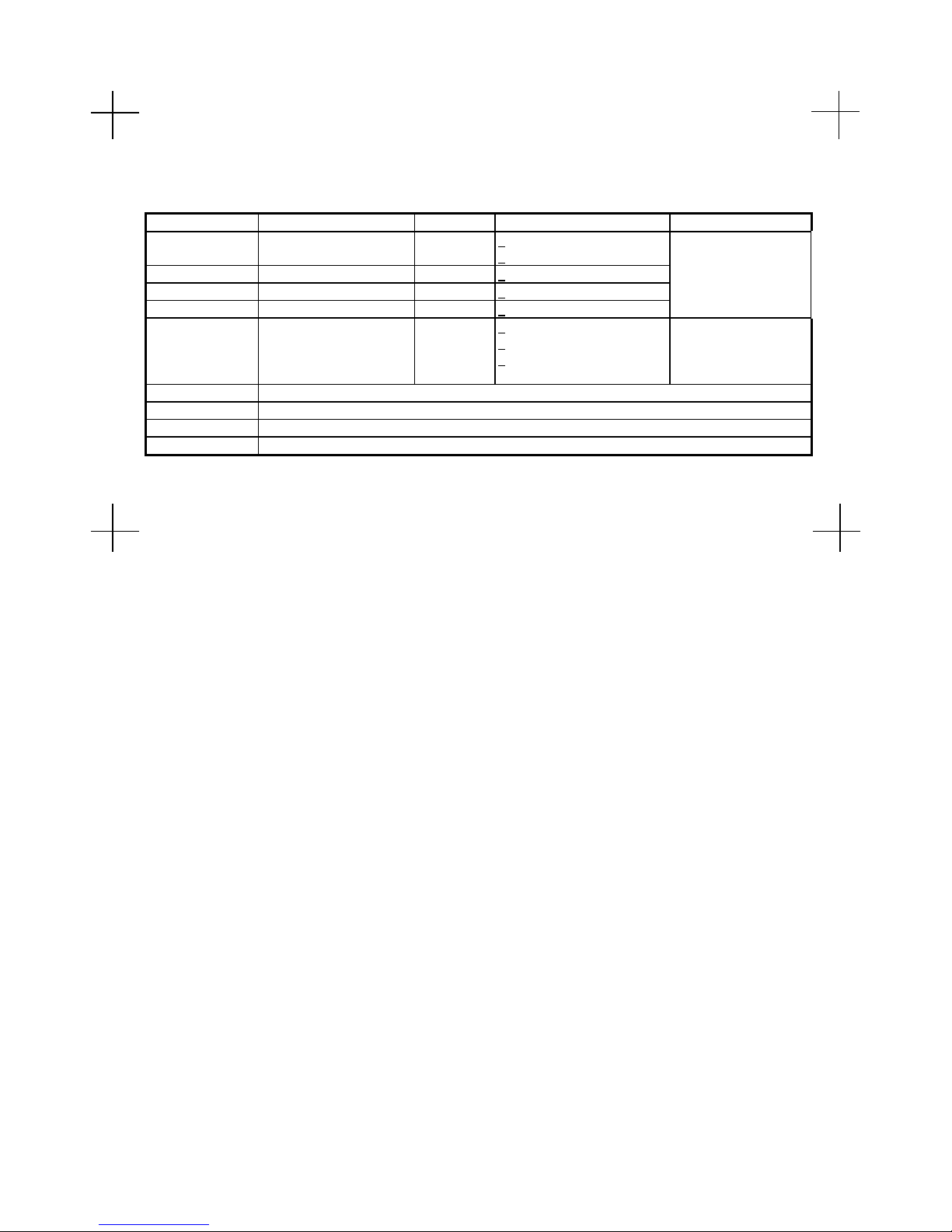
SPECIFICATIONS
Ranges Resolution Accuracy
DC Voltage 300mV, 3V
30,300, 500V
AC Voltage 3, 30, 300, 500V 1mV +(1.5% reading + 8 digits) AC Freq. Response:
DC Current 30, 300mA 10µA +(1.5% reading + 3 digits) 40Hz to 400Hz
AC Current 30, 300mA 10µA +(2.0% reading + 5 digits) Average responding
Resistance 300,3k,30k,300kΩ
3MΩ
30MΩ
Continuity Buzzer sounds for resistance less than 20 ohms (approximately)
Logic <1V Logic low, 1V to 2V Indeterminate, >2V Logic High, 3V reference, 220kΩ input impedance
Power supply Two 1.5V AAA batteries
Dimmensions/Wt. 1x7.5x1.9” (26x191x40mm) / 3.9oz (120gm)
100µV +(1.5% reading + 5 digits)
+(1.0% reading + 2 digits
0.1 ohms +(1.5% reading + 5 digits)
+(2.0% reading + 8 digits)
+(3.0% reading + 10 digits)
Input Impedance 10MΩ
Max Input 500V AC/DC
Overload Protection:
250VAC rms
Open ckt. V: 0.6V -
1.2V
SAFETY INSTRUCTIONS
Page 4

This meter has been designed to be safe in use, but the
rules listed below should be carefully followed for safe
operation.
1. NEVER apply voltage or current to the meter that
exceeds the specifications.
2. USE EXTREME CAUTION when working with high
voltages.
3. DO NOT measure voltage above 500V DC or AC rms.
4. ALWAYS turn off the power and disconnect the test
leads before replacing the fuse or battery.
FUNCTIONAL DESCRIPTION
1. Data Hold Button
2. Range Hold Button
3. DC/AC / Button
4. Function Switch
5. Green LED
6. Red LED
7 Common Terminal
8. Positive Test Probe
9. Battery & Fuse Door
10. LCD Display & Bargraph
11.
Function Switch Settings
Switch
Button V Ω A Logic
DC, DCV Ω DCA Logic
AC, ACV Ω ACA Logic
Page 5

Range Hold Button
The Resistance, AC or DC voltage or current ranges can
be selected manually or automatically. The Range Hold
button is used to select the range hold mode as follows.
1. Press to change from automatic to manual ranging.
“RH” is displayed in the manual range mode
2. Press to change range in the manual range mode.
Observe the decimal point position to determine the
range set.
3. Press and HOLD for 2 seconds to change back to
automatic ranging.
Data Hold Button
1. The display will hold the reading when the Data Hold
button is pressed. The “DH” symbol will be displayed.
2. Data Hold will be canceled when the “D-H” button is
pressed again or it will be canceled automatically if the
Function switch is changed to another position.
OPERATION
CAUTION: This meter is a precision electronic instrument.
To avoid damaging the unit, observe all safety statements
contained in this manual.
DC or AC Voltage Measurement
1. Connect the black test lead to the COM jack.
2. Set the Function Switch to the V position and select
AC or DC.
3. Connect the positive test probe and the black test lead
across the source or load under measurement.
For DC voltage, the polarity of the measurement will be
indicated.
DC or AC Current Measurement
1. Connect the black test lead to the COM jack.
2. Set the Function Switch to the mA position and select
DC or AC.
3. Connect the positive test probe and the black test lead
in series with load under measurement.
For DC current, the polarity of the measurement will be
indicated.
Page 6

Resistance Measurement
1. Connect the black test lead to the COM jack.
2. Set the Function Switch to the Ω position.
3. Connect the positive test probe and the black test
across the resistance to be measured.
Note: 1) The polarity of the positive test probe is “+”.
2) When checking in-circuit resistance, be sure all
power is removed from the circuit under test and
all capacitors are fully discharged.
Continuity Test
1. Connect the black test lead to the COM jack.
2. Set the Function Switch to the / position and
select with button 3.
3. Connect the positive test probe and the black test lead
to the circuit. If the resistance is less than
approximately 20Ω the buzzer will sound.
Note: The polarity of the positive test probe is “+”
Diode Test
1. Connect the black test lead to the COM jack.
2. Set the Function Switch to the / position and
select with Button(3)
3. Connect the positive test probe and the black test lead
across the diode under test. If the positive test probe is
placed on the anode of the diode, the display will
indicate the approximate forward voltage drop of the
diode.
Logic Test
1. Connect the black test lead to the COM jack.
2. Set the Function Switch to the L position
3. Connect the black test lead to the common terminal of
the circuit to be tested Connect the test probe to the
point to be tested.
a) If the measured voltage is below the low reference
threshold the GREEN led will light, indicating a logic
“0”.
b) If the measured voltage is above the high reference
threshold the RED led will light, indicating a logic “1”.
c) If the measured voltage is between the reference
thresholds, neither led will light.
Page 7

4. In the logic testing mode, the measured voltage is
displayed in the LCD.
Battery and Fuse Replacement
NOTE: Do not operate the instrument or connect the test
lead or probe to any circuit with the rear cover open.
1. Remove the screw and open the battery door. Replace
the old batteries or the blown fuse with the same type.
Fuse: 800mA/250V fast blow type
Battery: Two 1.5V AAA or UM-4 type
 Loading...