

Page 1
User's Guide
Frequency Counter
Model 381235
Introduction
Congratulations on your purchase of Extech’s Frequency Counter. This meter will measure
frequency to 2.5GHz using test leads or the optional RF antenna. This professional meter,
with proper care, will provide years of safe reliable service.
Page 2
2
Specifications
General Specifications
Display 0.5” (13mm) 8-digit LCD
Functions Frequency, Data Hold, Relative, Max/Min/Avg & Period
Input connectors BNC female
Meter housing Durable ABS plastic
Operating conditions 32 to 122oF (0 to 50oC); < 90% RH
Power supply 4 x 1.5V AA cells
AC adapter (option) 9VDC, 300 to 500mA (center socket pin positive)
Dimensions; weight 6.8 x 3.1 x 1.4” (173 x 80 x 35mm); 0.75 lbs (340g)
Electrical Specifications
Period range Ch. C: 10MHz
Resolution, sample rate and
sensitivity
Accuracy ± (4 ppm + 1 digit) @ 23oC ±5oC
Time base 4.194 MHz quartz crystal
Temp. coefficient 0.1 ppm per oC typical
Resolution and sampling rate specifications
Range Gate time selection Resolution (Hz) Sampling time (sec)
2500MHz
500MHz
10MHz
NOTE: In SLOW Gate Time mode (Gate switch set to SLOW), pressing the RESO key
scrolls the meter through SLOW, SLOW (Select1), and SLOW (Select 2) modes.
Sensitivity specifications
Ch.B: 500MHz range
Ch.C: 10MHz range, Period 50mVrms
Notes on sensitivity: The apparent sensitivity when feeding a signal into Ch.A may vary
considerably, particularly near 1GHz. The meter’s input impedance is a complex impedance,
whereas the output of most signal generators is calibrated for a 50Ω resistive load. This will
result in a terminal voltage different to that expected by the generator, and therefore a
different sensitivity.
105mA DC approx. 2500MHz/500MHz ranges Power consumption
45mA DC approx. for 10MHz & Period ranges
Ch. A: 2500MHz Frequency range
Ch. B: 500MHz
Refer to Sections 2.3 and 2.4 below
5V peak to peak max. for 2500/500MHz range Input overload
250V peak to peak max. for 10MHz & Period range
FAST 1000 0.5
SLOW 100 2.75
SLOW (select 1) 200 1.5
SLOW (select 2) 500 0.75
FAST 100 0.75
SLOW 10 6
SLOW (select 1) 20 5
SLOW (select 2) 50 1.5
FAST 10 0.5
SLOW 1 1.25
SLOW (select 1) 0.2 6
SLOW (select 2) 0.1 11
100mVrms (50MHz to 75MHz) Ch.A: 2500MHz range
50mVrms (76MHz to 2500MHz)
120mVrms (10M to 35MHz)
50mVrms (36M to 350MHz)
120mVrms (351M to 450MHz)
381235 Ver. 1.5 3/01
Page 3

3
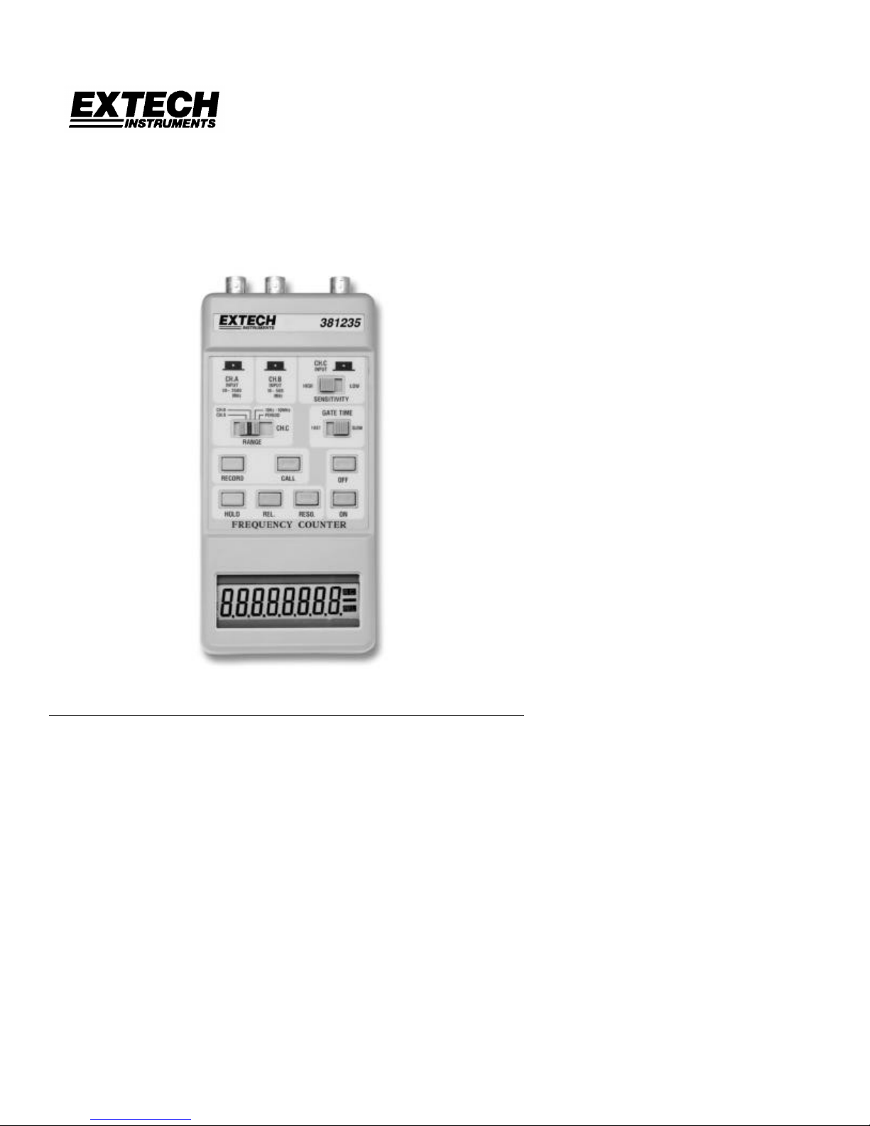
Front Panel Description
1. Channel A input
2. Ch. B input
3. Ch. C input
4. LCD display 8-digits
5. AC adapter jack (side)
6. Resolution key
7. Relative mode key
8. Data Hold key
9. Power ON key
10. Record mode key
11. Call mode key
12. Range select switch
13. Power OFF key
14. Gate time selecter switch
15. Sensitivity key
NOTE: Battery compartment is on lower
rear of meter secured by two screws
Operation
RF Antennae and Measurement Probes
The female BNC input sockets on the top of the meter accept RF Antennae or Direct
Measurement Probes with BNC connectors. These are optionally available through Extech
Instruments. Connect the RF Antennae or Direct Probes before powering the meter. It is
recommended that only RF Antennae be used for frequencies greater than 500MHz for
the best sensitivity.
Frequency measurements
1. Press the Power ON key to power the meter. If the display does not indicate digits
check the batteries or the AC adapter. To power down press the Power OFF key
2. Slide the Range selector switch to desired measurement range. Note that for the best
accuracy and resolution, be sure to use the most appropriate range.
3. Apply the measurement signal to the input Channel A socket if the frequency of the
signal is between 500MHz and 2500MHz.
4. Apply the measurement signal to the input Channel B socket if the frequency of the
signal is between 10MHz and 500MHz.
5. Apply the measurement signal to the input Channel C socket if the frequency of the
signal is less than 10MHz.
6. Slide the Sensitivity selector switch(es) to the HIGH or LOW setting if the measured
signal is less than 10MHz.
7. Slide the Gate select switch to the FAST or SLOW setting depending upon the desired
resolution and sampling rate (refer to the specifications section). Note that if SLOW is
selected, pressing the RESO key (up to 3 times) scrolls through up to 3
resolution/sampling rate display combinations. Press the RESO key and observe the
LCD each time for the different resolution/sampling rate combinations. The LCD flashes
at the sampling rate selected.
8. The units for the 500/2500MHz ranges is MHz and the units for the 10HMz range is Hz.
381235 Ver. 1.5 3/01
Page 4

4
Data Hold Mode
To freeze the most recent reading on the LCD, press the HOLD button once. The HOLD
icon will alternately appear on the LCD with the held reading. To release the reading and
return the meter to normal operation, press the HOLD key again.
Relative Mode Measurements
To display the difference between a stored reading and actual measurements, press the
REL key once. The reading at the time of the REL key-press will be stored in memory. All
subsequent displays will represent the difference between the stored reading and the
actual measurement. Press the REL key again to return to normal operation. Note that the
RELATIVE function cannot be accessed if the meter is in Data Hold or Data Record
modes.
Data Recording (Min/Max/Avg) Mode
The DATA RECORDING mode permits the maximum, minimum, and average readings to
be stored and recalled. To start recording data, press the RECORD key once and the R.C.
icon will appear on the right side of the LCD. After the measurement session, press the
CALL key to begin recalling the stored data.
The 1st CALL key press shows the maximum reading and the ‘Hi’ icon alternately.
The 2nd CALL key press shows the minimum reading and the ‘Lo’ icon alternately.
The 3rd CALL key press shows the average reading and the ‘A’ icon alternately. (The
Average reading will continue to update every 10 samples).
To return to normal operation, press the RECORD key again.
Period Measurements
Input the signal to Ch. C.
Slide the Range selector switch to the PERIOD position.
Period measurements are taken the same as frequency measurements.
The input frequency range for the PERIOD function is: 10Hz to 10MHz.
The display will show 5 digits with ‘S’ for millisecond or ‘uS’ for microsecond units of time.
The principle of the period display is a calculation which uses the measured frequency in
Hz. Refer to the following equations for the calculation the meter uses to display PERIOD:
Period (in milliseconds) = 1000ms / frequency (in Hz)
Period (in microseconds) = 1,000,000 uS / frequency (in Hz)
Auto Power OFF
If the meter is not used (keys pressed, switches moved) for approx. 30 mins. the meter will
automatically power itself down to preserve battery life.
Over Range Indication
The LCD will indicate –oL—and meter will emit an audible tone if one of the following
conditions are met:
a. Input signal exceeds 10MHz in 10MHz range
b. Input signal exceeds 500MHz in 500MHz range
c. Input signal = 0 (no input connected) for the PERIOD range.
381235 Ver. 1.5 3/01
Page 5

5
Maintenance
((
Battery Replacement
Note: Remove the probes or antennae before replacing the battery
a. When the display reading begins blinking, the battery voltage has fallen to critical
levels and requires replacing.
b. Loosen the battery compartment screws (lower left side of the case back).
c. Replace the 4 ‘AA’ 1.5V batteries and replace the cover.
Cleaning
Caution: Use only a dry (or slightly damp) cloth to clean the plastic case.
Calibration and Repair Services
Extech offers complete repair and calibration services for all of the products we sell. For
periodic calibration, NIST certification or repair of any Extech product, call customer
service for details on services available. Extech recommends that calibration be performed
on an annual basis to insure calibration integrity.
Warranty
EXTECH INSTRUMENTS CORPORATION warrants this instrument to be free of defects in parts and
workmanship for one year from date of shipment (a six month limited warranty applies on sensors and
cables). If it should become necessary to return the instrument for service during or beyond the warranty
period, contact the Customer Service Department at (781) 890-7440 for authorization. A Return
Authorization (RA) number must be issued before any product is returned to Extech. The sender is
responsible for shipping charges, freight, insurance and proper packaging to prevent damage in transit.
This warranty does not apply to defects resulting from action of the user such as misuse, improper wiring,
operation outside of specification, improper maintenance or repair, or unauthorized modification. Extech
specifically disclaims any implied warranties or merchantability or fitness for a specific purpose and will not
be liable for any direct, indirect, incidental or consequential damages. Extech's total liability is limited to
repair or replacement of the product.
The warranty set forth above is inclusive and no other warranty, whether written or oral, is expressed or
implied.
All rights reserved including the right of reproduction in whole or in part in any form.
Copyright © 2001 Extech Instruments Corporation.
Tech Support Hotlines
781-890-7440 ext. 200
extech@extech.com
www.extech.com
381235 Ver. 1.5 3/01
 Loading...