

Page 1
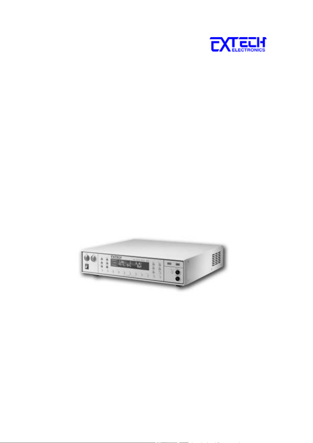
7611
LINE LEAKAGE TESTER
OPERATION MANUAL
EV 1.11
Printed Dec. 2005
Page 2

Page 3

WARRANTY POLICY
EXTECH ELECTRONICS CO., LTD., certifies that the instrument listed in this
manual meets or exceeds published manufacturing specifications. This instrument was
calibrated using standards that are traceable to the National Institute of Standards Taiwan.
Your new instrument is warranted to be free from defects in workmanship and material
for a period of (1) year from date of shipment. During the warranty period, you must
return the instrument to Extech Electronics Co., or its branches or its authorized
distributor for repair. Extech Electronics Co., reserves the right to use its discretion on
replacing the faulty parts or replacing the assembly or the whole unit.
Any unauthorized modification, tampering with or physical damage to this instrument
will render your warranty void. Elimination of any connection in the earth grounding
system or by-passing any safety system will void this warranty. This warranty does not
cover accessories not of Extech Electronics Co., Ltd. manufacture. Parts used must be
parts that are recommended by Extech Electronics Co. Ltd. as an acceptable specified
part. Use of non-authorized parts in the repair of this instrument will void the warranty.
Extech Electronics Co., Ltd. recommends that your instrument be calibrated on a twelve
month cycle.
Except as provided herein, Extech Electronics Co., Ltd. makes no warranties to the
purchaser of this instrument. All other warranties, express or implied are hereby excluded,
disclaimed and waived.
Page 4

Page 5

Index
Chapter 1 : Introduction ……………………………………1
Chapter 2 : Specifications …………………………………..10
Chapter 3 : Front And Rear Panels ……………………….13
Chapter 4 : Installation …………………………………….18
Chapter 5 : Quick Start …………………………………….20
Chapter 6 : General Setup Procedures ……………………23
Chapter 7 : Test Parameter Setup Procedures ……………25
Chapter 8 : System Parameter Setup ………………………30
Chapter 9 : Operation Procedure ………………………….34
Chapter 10 : LCD Displayed Messages ……………………37
Chapter 11 : Remote Operation ……………………………40
Chapter 12 : RS232 & GPIB Interface …………………….42
Chapter 13 : Options ………………………………………..50
Chapter 14 : Calibration Procedures ………………………52
Page 6

Page 7
INTRODUCTION
CHAPTER 1 : INTRODUCTION
1.1 GENERAL:
This product and its related documentation must be reviewed for familiarization with
safety markings and instructions before operation.
This product is a Safety Class I instrument (provided with a protective earth terminal).
Before applying power verify that the instrument is set to the correct line voltage (110 or
220) and the correct fuse is installed.
SAFETY SYMBOLS:
1.1.1
INSTRUCTION MANUAL SYMBOL. PLEASE REFER TO THE
INSTRUCTION MANUAL FOR SPECIFIC WARNING OR
CAUTION INFORMATION TO AVOID PERSONAL INJURY OR
WARNING
CAUTION
DAMAGE TO THE PRODUCT
INDICATES HAZARDOUS VOLTAGES MAY BE PRESENT.
CHASSIS GROUND SYMBOL.
CALLS ATTENTION TO A PROCEDURE, PRACTICE, OR
CONDITION, THAT COULD POSSIBLY CAUSE BODILY
INJURY OR DEATH.
CALLS ATTENTION TO A PROCEDURE, PRACTICE, OR
CONDITION, THAT COULD POSSIBLY CAUSE DAMAGE
TO EQUIPMENT OR PERMANENT LOSS OF DATA.
1
Page 8

INTRODUCTION
1.1.2 WARNING:
A Hipot produces voltages and currents which can cause harmful or fatal electric
shock. To prevent accidental injury or death, these safety procedures must be strictly
observed when handling and using the test instrument.
1.1.3 SERVICE AND MAINTENANCE
User Service
To prevent electric shock do not remove the instrument cover. There are no user
serviceable parts inside. Routine maintenance or cleaning of internal parts is not
necessary. Any external cleaning should be done with a clean dry or slightly damp cloth.
Avoid the use of cleaning agents or chemicals to prevent any foreign liquid from
entering the cabinet through ventilation holes or damaging controls and switches, also
some chemicals may damage plastic parts or lettering. Schematics, when provided, are
for reference only. Any replacement cables and high voltage components should be
acquired directly from Associated Research, Inc. Refer servicing to a Extech Electronics
Co., Ltd. authorized service center.
Service Interval
The instrument and its power cord, test leads, and accessories must be returned at least
once a year to a Extech Electronics Co., Ltd. authorized service center for calibration and
inspection of safety related components. Extech Electronics Co., Ltd. will not be held
liable for injuries suffered if the instrument is not returned for its annual safety check and
maintained properly.
User Modifications
Unauthorized user modifications will void your warranty. Extech Electronics Co., Ltd.
will not be responsible for any injuries sustained due to unauthorized equipment
modifications or use of parts not specified by Associated Research. Instruments returned
to Extech Electronics Co., Ltd. with unsafe modifications will be returned to their
original operating condition at your expense.
1.1.4 OPERATING, STORAGE AND SHIPMENT ENVIRONMENT
Operating Environment
This instrument may be operated in temperatures from 0° - 40° C. and relative humidity
of 20 to 80%, altitude 2000 meters (6560 feet)
.
Storage Environment
This instrument may be stored or shipped in environments with the following limits:
Temperature......................... -40° to 75°C
Altitude..........................….. 7,620 meters (25,000 feet)
The instrument should also be protected against temperature extremes, which may cause
condensation within the instrument.
2
Page 9

INTRODUCTION
Shipment Environment
Original Packaging: Please retain all original packaging materials that you originally
received. If you are returning your instrument to us for servicing please repackage the
instrument in its original container. Please enclose the instrument with all options,
accessories and test leads. Indicate the nature of the problem or type of service needed.
Also, please mark the container "FRAGILE" to insure proper handling.
Other Packaging: If you do not have the original packaging materials please follow these
guidelines:
1). Wrap the instrument in a bubble pack or similar foam. Enclose the same information
as above.
2). Use a strong double-wall container that is made for shipping instrumentation. 350 lb.
test material is adequate.
3). Use a layer of shock-absorbing material 70 to 100 mm (3 to 4 inch) thick around all
sides of the instrument. Protect the control panel with cardboard.
4). Seal the container securely.
5). Mark the container "FRAGILE" to insure proper handling.
3
Page 10

INTRODUCTION
1.2 Product Safety Testing
The importance of testing... User safety
Product Safety Tests are specified during the design and development stages of a product
as well as in the production of the products to insure that it meets basic safety
requirements. These tests are designed to verify the safety of the electrical products in
that they do not jeopardize the safety of the people, domestic animals, and property of
anyone who may come in contact with these products. In an era of soaring liability costs,
original manufacturers of electrical and electronic products must make sure every item is
as safe as possible. All products must be designed and built to prevent electric shock,
even when users abuse the equipment or by-pass built in safety features.
To meet recognized safety standards, one common test is the "dielectric voltagewithstand test". Safety agencies which require compliance safety testing at both the
initial product design stage and for routine production line testing include: Underwriters
Laboratories, Inc. (UL), the Canadian Standards Association (CSA), the International
Electrotechnical Commission (IEC), the British Standards Institution (BSI), the
Association of German Electrical Engineers (VDE) and (TÜV), the Japanese Standards
Association (JSI). These same agencies may also require that an insulation resistance test
and high current ground bond test be performed.
1.3 Line Leakage Testing
The Line Leakage test is one of many product safety tests which are normally specified
for electrical products by safety testing agencies such as Underwriters Laboratories (UL)
and the International Electrotechnical Committee (IEC). The line leakage specifications
vary as well as the method in which the measurements are taken depending upon the
application or function of a product and the standard to which the product is being tested.
Current Leakage or Line Leakage tests are general terms that actually describe three
different types of tests. These tests are Earth Leakage Current, Enclosure Leakage
Current, and Applied Part Leakage Current. The main differences in these tests are in the
placement of the probe for the measuring device. The Earth Leakage Current is the
leakage current which flows through the ground conductor in the line cord back to earth.
The Enclosure Leakage Current is the current that flows from any enclosure part through
a person back to ground if it were contacted by a person. The Applied Part Leakage
Current or Patient Lead Leakage Current is any leakage that flows from an applied part,
between applied parts or into an applied part. The Applied Part Leakage Current test is
required only for medical equipment. All of these tests are used to determine if products
can be safely operated or handled without posing a shock hazard to the user.
The Model 7611 Line Leakage Tester provides the capability of meeting the line leakage
test specified in the following standards; UL 544, IEC 950, UL 1950, IEC 601-1, UL
2601, UL 1563, UL 3101, IEC 1010 and others. The Line Leakage test is a test which
measures the leakage current of a product through a circuit which is designed to simulate
4
Page 11

INTRODUCTION
the impedance of the human body , this circuit is called the Measuring Device (MD).
The instrument has five different MD circuits, selectable through the menu, which are
representative circuits designed to simulate the impedances of the human body under
different conditions. The impedance of the human body will vary depending upon point
of contact, the surface area of the contact and the path the current flows. For these
reasons the specifications on the Measuring Devices differ depending upon the type of
test being performed as well as the maximum allowable leakage current. Leakage current
measurements are performed on products under both normal conditions and single fault
conditions as well as reversed polarity. This simulates possible problems which could
occur if the product under test is faulted or misused while the product is operating under
high line conditions (110% of the highest input voltage rating of the product).
Line Leakage tests are normally specified as “Type Tests” or “Design Tests” which are
performed during the development of the product. This helps verify that the design is safe
but it does not guarantee the safety of the products being produced on the production line.
The only way to be sure you are shipping safe products is to test each product at the end
of the production line. The built in switching matrix interface allows the 7611 to be
interconnected with other AR safety testers to form a complete safety testing system.
The user may perform a Leakage Current test along with other common safety test such
as Dielectric Withstand, Insulation Resistance, and Ground Bond on the production line
with a single connection to the device under test.
1.4 The Dielectric Withstand (Hipot) Test
The principle behind a dielectric voltage - withstand test is simple. If a product will
function when exposed to extremely adverse conditions, it can be assumed that the
product will function in normal operating circumstances.
The most common applications of the dielectric-withstand test are:
Design (performance) Testing.... determining design adequacy to meet service
•
conditions.
Production Line Testing.... detecting defects in material or workmanship during
•
processing.
Acceptance Testing.... proving minimum insulation requirements of purchased parts.
•
Repair Service Testing.... determine reliability and safety of equipment repairs.
•
The specific technique varies with each product, but basically, during a dielectric voltage
- withstand test, an electrical devise is exposed to a voltage significantly higher than it
normally encounters. The high voltage is continued for a given period of time.
5
Page 12

INTRODUCTION
During the test, all "stray" current flow to ground is measured. If, during the time the
component is tested, stray current flow remains within specified limits, the device is
assumed to be safe under normal conditions. The basic product design and use of the
insulating material will protect the user against electrical shock.
The equipment used for this test, a dielectric-withstand tester, is often called a "hipot"
(for high potential tester). The "rule of thumb" for testing is to subject the product to
twice its normal operating voltage, plus 1,000 volts.
However, specific products may be tested at much higher voltages than 2X operating
voltages + 1,000 volts. For example, a product designed to operate in the range between
100 to 240 volts, can be tested between 1,000 to 4,000 volts or higher. Most "double
insulated" products are tested at voltages much higher than the "rule of thumb".
Testing during development and prototype stages is more stringent than production run
tests because the basic design of the product is being evaluated. Design tests usually are
performed on only a few samples of the product. Production tests are performed on each
and every item as it comes off the production line.
The hipot tester must also maintain an output voltage between 100% and 120% of
specification. The output voltage of the hipot must have a sinusoidal waveform with a
frequency between 40 to 70 Hz and has a peak waveform value that is not less than 1.3
and not more than 1.5 times the root-mean-square value.
1.5 Advantages and Disadvantages of AC Testing and DC Testing....
Please check with the Compliance Agency you are working with to see which of the two
type of voltages you are authorized to use. In some cases a Compliance Agency will
allow either AC or DC testing to be done. However in other cases the Compliance
Agency only allows for an AC test. If you are unsure which specification you must
comply with please contact our CUSTOMER SUPPORT GROUP at 02-26943030.
Many safety agency specifications allow either AC or DC voltages to be used during the
hipot test. When this is the case the manufacturer must make the decision on which type
of voltage to utilize. In order to do this it is important to understand the advantages and
the disadvantages of both AC and DC testing.
AC testing characteristics
1.5.1
Most items that are hipot tested have some amount of distributed capacitance. An AC
voltage cannot charge this capacitance so it continually reads the reactive current that
flows when AC is applied to a capacitive load.
AC testing advantages
1.5.2
1. AC testing is generally much more accepted by safety agencies than DC testing.
The main reason for this is that most items being hipot tested will operate at AC
voltages and AC hipot testing offers the advantage of stressing the insulation
6
Page 13

INTRODUCTION
alternately in both polarities which more closely simulates stresses the product will
see in real use.
2. Since AC testing cannot charge a capacitive load the current reading remains
consistent from initial application of the voltage to the end of the test. Therefore,
there is no need to gradually bring up the voltage since there is no stabilization
required to monitor the current reading. This means that unless the product is
sensitive to a sudden application of voltage the operator can immediately apply full
voltage and read current without any wait time.
3. Another advantage of AC testing is that since AC voltage cannot charge a load there
is no need to discharge the item under test after the test.
AC testing disadvantages
1.5.3
1. A key disadvantage of AC testing surfaces when testing capacitive products. Again,
since AC cannot charge the item under test, reactive current is constantly flowing.
In many cases the reactive component of the current can be much greater than the
real component due to actual leakage. This can make it very difficult to detect
products that have excessively high leakage current.
2. Another disadvantage of AC testing is that the hipot has to have the capability of
supplying reactive and leakage current continuously. This may require a current
output that is actually much higher than is really required to monitor leakage current
and in most cases is usually much higher than would be needed with DC testing.
This can present increased safety risks as operators are exposed to higher currents.
DC testing characteristics
1.5.4
During DC hipot testing the item under test is charged. The same test item capacitance
that causes reactive current in AC testing results in initial charging current which
exponentially drops to zero in DC testing.
DC testing advantages
1.5.5
1. Once the item under test is fully charged the only current flowing is true leakage
current. This allows a DC hipot tester to clearly display only the true leakage of the
product under test.
2. The other advantage to DC testing is that since the charging current only needs to be
applied momentarily the output power requirements of the DC hipot tester can
typically be much less than what would be required in an AC tester to test the same
product.
1.5.6 DC testing disadvantages
1. Unless the item being tested has virtually no capacitance it is necessary to raise the
voltage gradually from zero to the full test voltage. The more capacitive the item
the more slowly the voltage must be raised. This is important since most DC hipots
7
Page 14

INTRODUCTION
have failure shut off circuitry which will indicate failure almost immediately if the
total current reaches the leakage threshold during the initial charging of the product
under test.
2. Since a DC hipot does charge the item under test it becomes necessary to discharge
the item after the test.
3. DC testing unlike AC testing only charges the insulation in one polarity. This
becomes a concern when testing products that will actually be used at AC voltages.
This is a key reason that some safety agencies do not accept DC testing as an
alternative to AC.
4. When performing AC hipot tests the product under test is actually tested with peak
voltages that the hipot meter does not display. This is not the case with DC testing
since a sinewave is not generated when testing with direct current. In order to
compensate for this most safety agencies require that the equivalent DC test be
performed at higher voltages than the AC test. The multiplying factor is somewhat
inconsistent between agencies which can cause confusion concerning exactly what
equivalent DC test voltage is appropriate.
1.6 The Insulation Resistance Test....
Some "dielectric analyzers today come with a built in insulation resistance tester.
Typically the IR function provides test voltages from 500 to 1,000 volts DC and
resistance ranges from kilohms to gigaohms. This function allows manufacturers to
comply with special compliance regulations. BABT, TÜV and VDE are agencies that
may under certain conditions require an IR test on the product before a Hipot test is
performed. This typically is not a production line test but a performance design test.
The insulation resistance test is very similar to the hipot test. Instead of the go/no go
indication that you get with a hipot test the IR test gives you an insulation value usually
in Megohms. Typically the higher the insulation resistance value the better the condition
of the insulation. The connections to perform the IR test are the same as the hipot test.
The measured value represents the equivalent resistance of all the insulation which exists
between the two points and any component resistance which might also be connected
between the two points.
Although the IR test can be a predictor of insulation condition it does not replace the
need to perform a dielectric withstand test.
1.6.1 TYPES OF FAILURES DETECTABLE ONLY WITH A HIPOT
TEST
Weak Insulating Materials
•
8
Page 15
INTRODUCTION
Pinholes in Insulation
•
Inadequate Spacing of Components
•
Pinched Insulation
•
1.7 The Ground Bond Test
The Ground Bonding test determines whether the safety ground circuit of the product
under test can adequately handle fault current if the product should ever become
defective. A low impedance ground system is critical in ensuring that in the event of a
product failure a circuit breaker on the input line will act quickly to protect the user from
any serious electrical shock.
International compliance agencies such as CSA, IEC, TÜV, VDE, BABT and others,
have requirements calling out this test. This test should not be confused with simple low
current continuity tests that are also commonly called out in some safety agency
specifications. A low current test merely indicates that there is a safety ground
connection, it does not completely test the integrity of that connection.
Compliance agency requirements vary on how different products are to be tested. Most
specifications call for test currents of between 10 and 30 amps. Test voltages at these
currents are typically required to be less than 12 volts. Maximum allowable resistance
readings of the safety ground circuit are normally between 100 and 200 milliohms.
IF YOU SHOULD HAVE ANY QUESTIONS RELATING TO THE OPERATION
OF YOUR INSTRUMENT CALL 886-2-26943030 IN TAIWAN.
9
Page 16
SPECIFICATIONS
CHAPTER 2 : SPECIFICATIONS
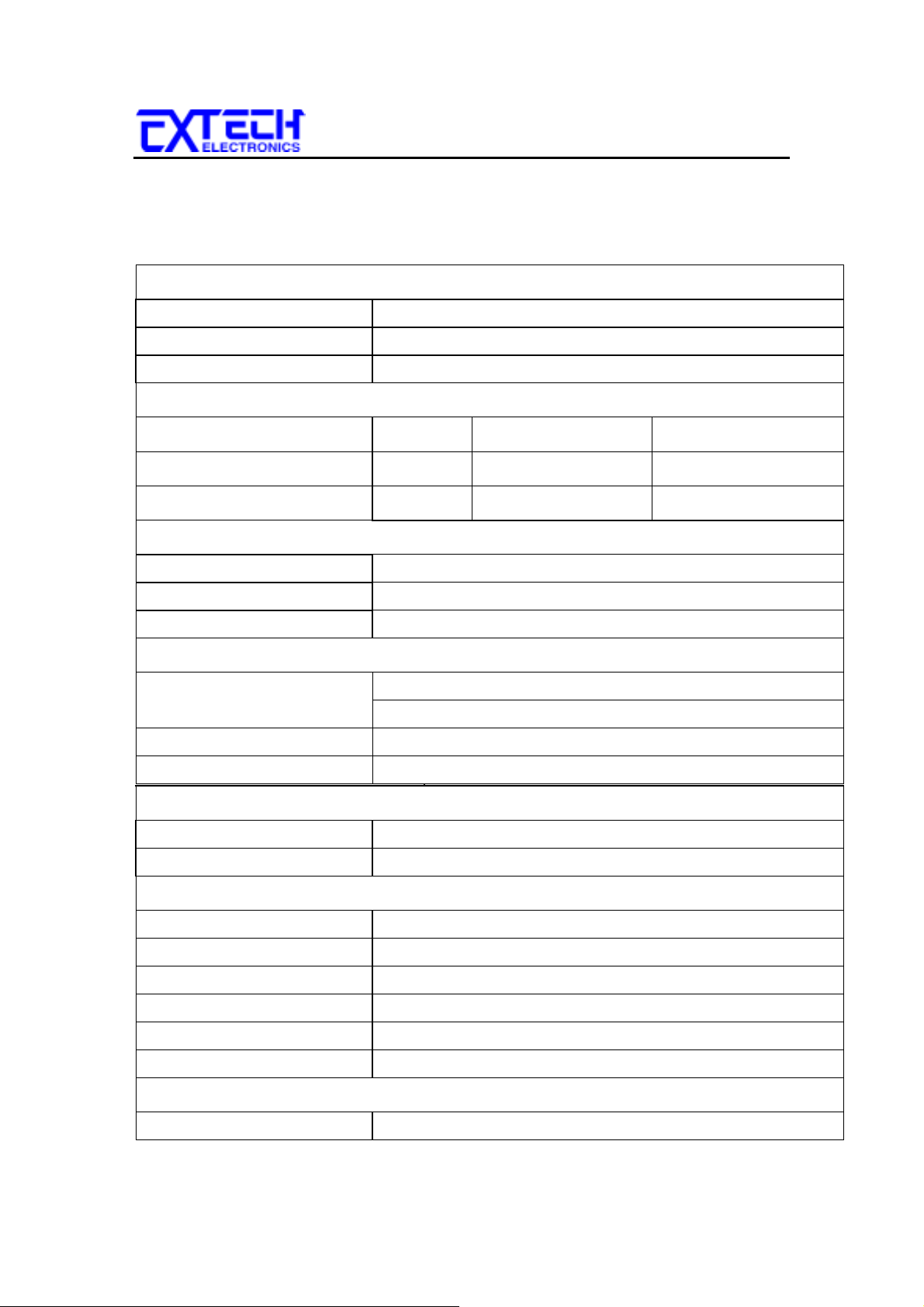
2.1 Functional Specifications of 7611
CURRENT MEASUREMENT
Frequency Range DC – 1MHz
CMRR >40 dB @1MHz, differential mode
Input Impedance/Capacitance >1MΩ / <200pf
LEAKAGE CURRENT
Range Resolution Accuracy (DC - 200KHz) Accuracy(10KHz - 1MHz)
0.0-999.9, µA 0.1
1000-6000, µA 1
LINE VOLTAGE MEASUREMENT
Range 0-300Vac
Resolution 0.1V
Accuracy ±(1% of reading +2counts)
DUT
30 –300 VAC Input Power Rating
±(1.5% of reading+5counts)
±(1.5% of reading+2counts)
Single Phase Unblanced(One Hot or Line conductor and One Neutral)
Current Capatcity 30 A
Production 32 A ,Short current, Response Time < 600ms
SETTINGS
High/Low Trip, µA 0 - 6000µA (0=OFF), Resolution 1µA
Delay Time, second 0, 1.0-999.9s (0=Continuous), Resolution 0.1s
MEASURING DEVICES CIRCUIT
±(5% of reading+5counts)
±(5% of reading+5counts)
MD A
MD B UL 544 Patient Care
MD C
MD D
MD E
MD F External MD
GENERAL
Input Voltage 115/230 Vac ±15%, 50/60Hz ±5%, Fuse 2A/250V Slow-Blow fuse
UL 544 Non Patient、UL484、IEC60598
IEC60601-1, UL2601-1, EN60601-1
UL1563
UL 60950, IEC60950, IEC61010-1, IEC60335-1,IEC60990
10
Page 17
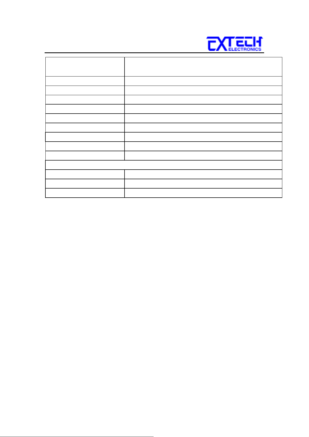
SPECIFICATIONS
PLC Remote Control
Memory 10 Memories, 8 step/memory
Display
Key Lock To prevent unauthorized alteration of the test Parameters
Calibration Build-in software and external calibrated meters
Interface GPIB/ RS232 (option)
Alarm Volume Setting Range:0-9; 0=OFF, 1 is softest volume, 9 is loudest volume
Environment 0 – 40°C, 20 – 80%RH
Dimension 430(W) × 89(H) × 400(D) mm
Net Weight 7.5 Kg.
STANDARD ACCESSORY
1102 ×2
1761 ×1
1906 ×1
Input :Test, Reset, Memory 1, 2 ,3
Output --- Pass, Fail, Processing
16×2 LCD with back light
11
Page 18
SPECIFICATIONS
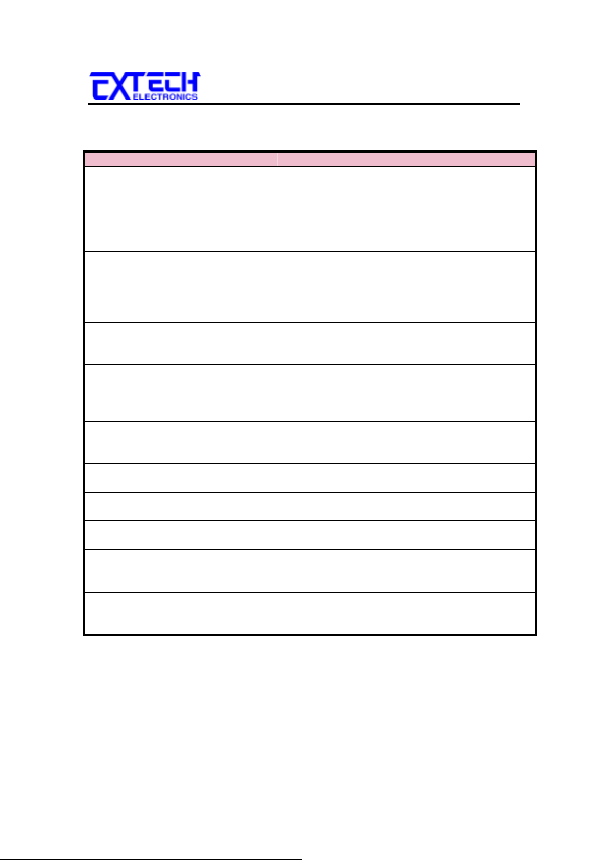
2.2 KEY FEATURES & BENEFITS SUMMARY
FEATURES
Provides 8 of the most common
safety tests
The 5 most common measuring
devices are built-in and can be
selected through software control
BENEFITS
No need to manually set up the test or to switch test
leads around.
A versatile tester that can be set-up to meet
multiple specifications without the need for
complicated external connections, or the need for
separate instruments.
Fully complies with the latest
European Norms
Programmable security password
system
Complies with the latest EN such as the Low
Voltage Directive and Medical Directive.
Avoids tampering with settings by only allowing
authorized personnel with a user programmable
security password to change test parameters.
Front panel calibration All calibration is done through a simple user
interface from the front panel. No need to open the
instrument.
PLC, RS-232 or GPIB Control Provides flexibility for semi-automatic or automatic
operation with a choice of communication
protocols which provides the capability for easy
test data storage.
Microprocessor control with software
menuing
Microprocessor control allows for many advanced
features such as automatic testing, memories and
software control.
External measurement circuit One external measurement circuit is provided for
measurement of other devices.
Separate current trip points for each
test
Each test can have a separate trip point for failure
analysis.
50 Memories for test storage Storage of test set-ups so parameters only need to
be entered once then memorized.
Complete with software driver
National Instruments LabVIEW software driver
is provided for automated applications to ease the
testing process.
Ranges from DC to 1 MHz Complies with even the 1 MHz specification for
IEC testing.
12
Page 19
FRONT AND REAR PANELS
CHAPTER 3 : FRONT AND REAR PANELS
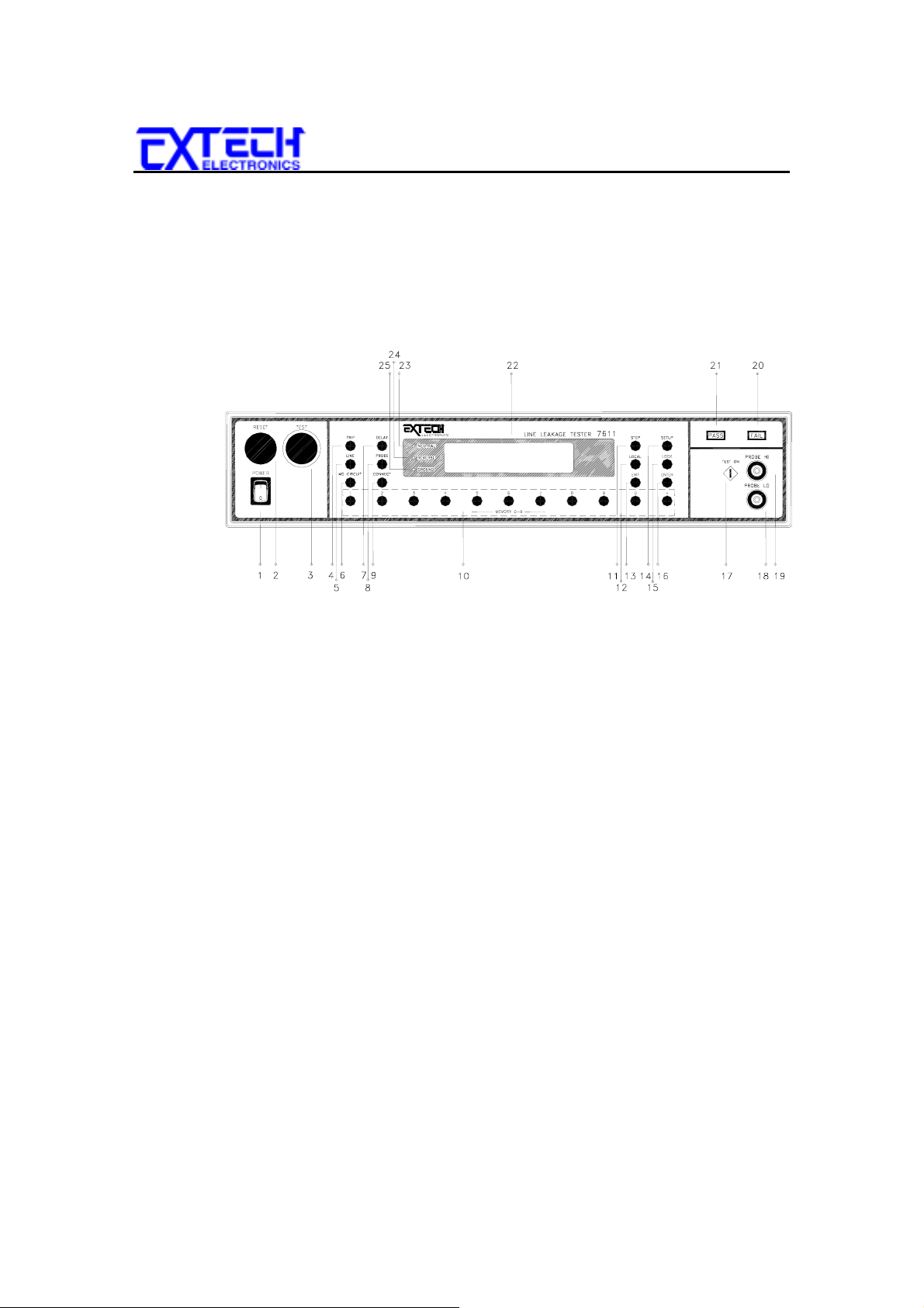
FRONT PANEL DESCRIPTION
3.1
1. POWER SWITCH:
markings.
2. RESET BUTTON:
occurs during a test you will need to reset the system to shut off the alarm and to
signal the system that you are aware of a failure condition before you can proceed to
the next test or change any of the set-up parameters. This switch also serves as an
abort signal to stop any test in progress controlled by the Line Leakage Tester.
3. TEST SWITCH:
activate the leakage test which is set up in the memory location shown on the display.
The switch will also illuminate to indicate a pass condition at the end of the test.
4. TRIP:
Use this key to set the trip current level for each step.
Rocker-style switch with international ON ( l ) and OFF (O)
This is a momentary contact switch. If a failure condition
This is a momentary contact switch. Press the green button to
13
Page 20

FRONT AND REAR PANELS
5. LINE:
Use this key to activate the NEUTRAL, REVERSE, and GROUND relays to
set up the steps within each memory for the single fault and normal conditions.
6. MD CIRCUIT:
Use this key to select the Measuring Device (MD) circuit A through
F to simulate different body impedances. This setting will vary depending upon the
standard to which the product is being tested. The Line Leakage Tester has 5 internal
MD circuits A-E which are shown below and 1 external measuring device which can
be added if a new requirement is needed.
MD = A
UL 544 MEDICAL EQUIPMENT
Non patient equipment.
MD = B
UL 544 MEDICAL EQUIPMENT
Patient care equipment.
MD = C
IEC 601-1, UL 2601, EN 60601-1,
MEDICAL EQUIPMENT
MD = D
UL 1563 Electric Spas,
Equipment Assemblies and
Associated Equipment
MD = E
IEC 1010, UL 3101, IEC 950, UL 1950, EN 60950 LABORATORY EQUIPMENT,
INFORMATION TECHNOLOGY
7. DELAY:
Use this key to program the delay time for making the leakage
measurement for each step.
8. PROBE:
Use this key to select the location of the MD circuit for the type of test being
performed. G-L indicates the MD is connected to measure the leakage current in the
earth ground conductor in the line cord back to the system neutral, an EARTH
LEAKAGE TEST. P
L indicates the MD is connected between the PROBE-HIGH (P
-
H
terminal # 27 on the instrument which should be connected to the ENCLOSURE of the
DUT through the system neutral, an ENCLOSURE LEAKAGE TEST. P
the MD is connected between the P
and the PROBE-LO (PL) terminal # 26 on the
H
H-PL
indicates
instrument which allow the operator to connect the MD between APPLIED PARTS.
9. CONNECT:
Use this key to sequence one step to the next step. The display will
indicate M1-1_. The underbar indicates that step 1 is connected to step 2.
10. DATA ENTRY KEYS:
Use these keys to input numeric parameters followed by the
ENTER key. Also used to recall test parameters stored in memory 0-9.
11. STEP:
Use this key to select one of the 8 locations contained within each memory.
The step button will cycle through the steps as indicated on the display in the Set
Screen. M1-1, M1-2, M1-3, etc.
)
H
14
Page 21

FRONT AND REAR PANELS
12. LOCAL:
To change the operation of the instrument from remote to the Local mode.
13. EXIT:
To exit any menu or to clear an unwanted entry in a parameter field.
14. SETUP:
Use this key to enter the setup menu. View or change the PLC Remote
status, display contrast, alarm volume, GPIB address, Fail Stop setting, Single Step,
and Memory Lock function.
15. LOCK:
Use this key to select key lockout mode. A password may be used when
setup (Please refer to sections General Setup and System Setup).
16. ENTER / REVIEW KEY:
Use this key as an ENTER key to accept numeric data
for parameter settings. Or use this key as a REVIEW key to recall up to 16 connected
test results after a test has been completed.
17. TEST LED:
This indicator will illuminate when the DUT has voltage applied to it,
and the Line Leakage test is active.
18. PROBE LO:
pressing the PROBE button # 7, when the display indicates P
This connector is an input to one side of the MD which is activated by
for performing
H-PL
Applied Part leakage measurements.
19. PROBE HI:
pressing the PROBE button # 7, when the display indicates either P
This terminal is an input to one side of the MD which is activated by
-L or PH-PL for
H
performing Enclosure leakage or Applied Part leakage measurements. When doing an
Enclosure Leakage test the lead from the Probe HI terminal should be connected to
the enclosure. When performing an Applied Part test the lead should be connected to
the applied part.
20. FAIL INDICATOR:
This LED indicator lights at the end of a test if a failure has
occurred during the test. Press the Reset button to clear the failure.
21. PASS INDICATOR:
not occurred.
This LED indicator lights at the end of a test if a failure has
22. LCD DISPLAY:
The 2x16 character display indicates the following test functions
during a test; Probe Connections, Measuring Device Selection, Delay Time, Memory,
Step Location, Input Voltage to DUT, and Leakage Current Reading. The display
23. NEUTRAL LED:
This indicator will illuminate when the neutral conductor to the
DUT is opened. This is one of the single fault conditions which is simulated during
the leakage test.
15
Page 22
FRONT AND REAR PANELS
24. REVERSE LED:
This indicator will illuminate when the input power polarity to the
DUT is reversed.
25. GROUND LED:
This indicator will illuminate when the ground conductor to the
DUT is open. This is one of the single fault conditions which is simulated during the
leakage test.
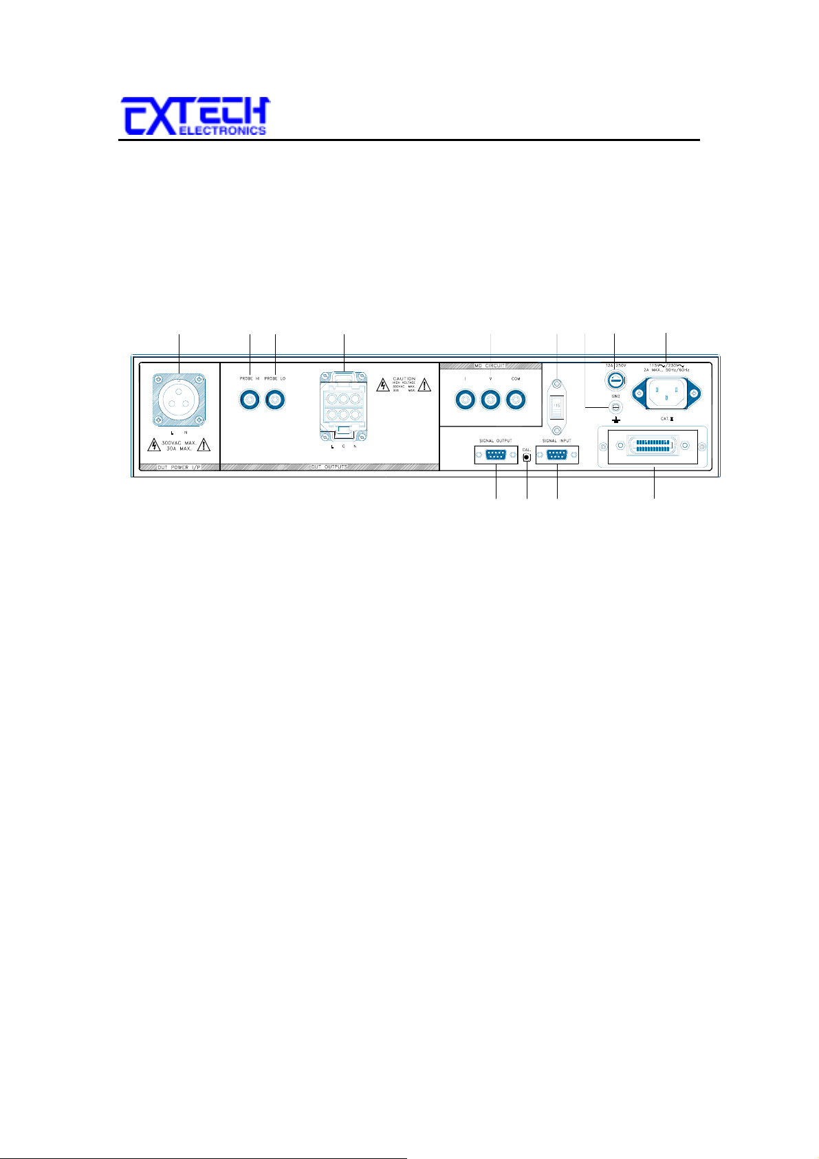
3.2 REAR PANEL DESCRIPTION
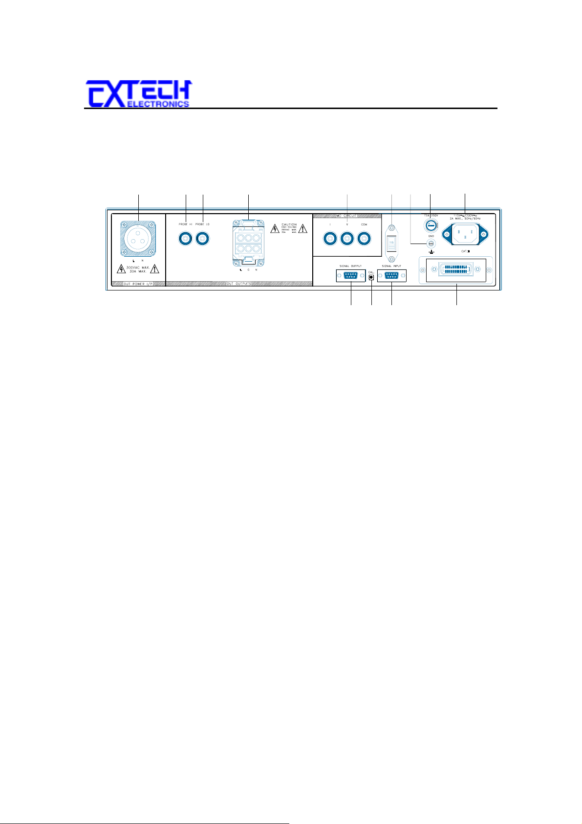
1 23 4
1. DUT POWER INPUT TERMINAL:
This connector is the LINE and NEUTRAL
input power connections. An external single phase unbalanced AC power supply with
a single Hot or Line conductor should be connected here, to supply power to the DUT
while performing the leakage test. This input is rated for 0-300 volts, 30 A maximum.
2. PROBE HI:
This terminal is an input to one side of the MD which is activated by
pressing the PROBE button #7, when the display indicates either P
performing Enclosure leakage or Applied Part leakage. This terminal and the PROBE
HI terminal # 25 on the front panel are connected in parallel during the Line Leakage
test. When the external link is active this terminal is isolated from the line leakage
test circuits.
3. PROBE LO:
This terminal is an input to one side of the MD which is activated by
pressing the PROBE button #7, when the display indicates P
Applied Part leakage measurements. This terminal and the PROBE LO terminal # 24
on the front panel are connected in parallel during the Line Leakage test. When the
external link is active this terminal is isolated from the line leakage test circuits.
4. DUT OUTPUT TERMINAL:
This output terminal is where the LINE, NEUTRAL
and GND power connections from the adapter box is plugged into the Line Leakage
Tester. Line power is supplied to the DUT during the leakage test through this terminal.
This output is rated for 0-300 volts, 30 A maximum.
5. EXTERNAL MEASURING DEVICE CONNECTORS:
the operator to connect an external Measuring Device circuit to the Line Leakage
Tester. These terminals are activated when the display indicates MD=F. The
5
10 11 12 13
67
-L or PH-PL for
H
for performing
H-PL
8
These connectors allow
9
16
Page 23
FRONT AND REAR PANELS
external measuring device may allow the operator to test to a different standard,
which calls for a different measuring device, or to easily change the measuring device
if the standard requirements change.
1 23 4
5
10 11 12 13
678
6. INPUT POWER SWITCH:
Line voltage selection is set by the position of this
switch. In the down position it is set for 110-120 volt operation, in the up position it
is set for 220-240 volt operation.
7. CHASSIS GROUND (EARTH) TERMINAL:
to a good earth ground before operation.
8. FUSE RECEPTACLE:
To change the fuse unplug the power (mains) cord and turn
This terminal should be connected
the fuse receptacle counter-clockwise. The fuse compartment will be exposed.
Please replace the fuse with one of the proper rating.
9. INPUT POWER RECEPTACLE:
standard NEMA style line power (mains) cord.
10. REMOTE SIGNAL OUTPUT:
Standard IEC 320 connector for connection to a
9-Pin D subminiature female connector for
monitoring PASS, FAIL, and PROCESSING output relay signals.
11. CALIBRATION ENABLE KEY:
This key is used during power up to enable the
calibration routines.
12. REMOTE SIGNAL INPUT:
9-Pin D subminiature male connector for remote
control of test and reset functions as well as program memory selection 1, 2, or 3.
13. GPIB:
Standard connector for interconnection to the GPIB interface. Optional RS-
232 interface can be substituted for this interface.
9
17
Page 24
INSTALLATION
CHAPTER 4 : INSTALLATION
This section contains information for the unpacking, inspection, preparation for use and
storage of your Extech Electronics Co., Ltd. product.
4.1 Unpacking and Inspection
If the shipping carton is damaged, inspect the contents for visible damage such as dents,
scratches or broken meters. If the instrument is damaged, notify the carrier and the
Extech Electronics Co., Ltd. customer support department immediately. Please save the
shipping carton and packing material for the carriers inspection. Our customer support
department will assist you in the repair or replacement of your instrument. Please do not
return your product without first notifying us and receiving an RMA (return material
authorization) number.
4.2 PREPARATION FOR USE
Power Requirements and Line Voltage Selection
4.2.1
This instrument requires a power source of either 115 volts AC ± 15%, 47-63 Hz single
phase or 230 volts AC ±15%, 47-63 Hz single phase. Please check the rear panel to be
sure the proper switch setting is selected for your line voltage requirements before
turning your instrument on.
CAUTION
damage and represents a safety risk to the operator.
NOTE:
For operation at 115 and 230 Volts AC use a 2A slow-blow fuse.
Power Cable
WARNING
LINE (MAINS) POWER CORD. THE MAIN PLUG SHALL ONLY BE INSERTED IN A
SOCKET OUTLET (RECEPTACLE) PROVIDED WITH A PRO TECTIV E GROUND (EARTH)
CONTACT. THIS PROTECTIVE GROUND (EARTH) MUST NOT BE DEFEATED
USE OF AN EXTENSION CORD (POWER C ABLE) WITHOUT A PROTECTIVE CONDUCTOR
(GROUNDING).
This instrument is shipped with a three-wire power cable. When this cable is connected
to an appropriate AC power source, this cable connects the chassis to earth ground. The
type of power cable shipped with each instruments depends on the country of destination.
Do not switch the line voltage selector switch located on the rear panel
while the instrument is on or operating. This may cause internal
BEFORE CONNECTING POWER TO THIS INSTRUMENT, TH E
PROTECTIVE GROUND (EARTH) TERMINALS OF THIS INSTRUMENT
MUST BE CONNECTED TO THE PROTECTIVE CONDUCTO R OF THE
BY THE
18
Page 25

INSTALLATION
Operating Environment
4.2.2
This instrument may be operated in temperatures from 32° - 104° F (0° - 40° C).
Relative humidity of 20 to 80%.
Altitude up to 6500 feet (2,000 meters).
4.3 STORAGE AND SHIPMENT
Environment
4.3.1
This instrument may be stored or shipped in environments with the following limits:
Temperature......................... -40° to 75°C
Altitude............................ 7,620 meters (25,000 feet)
The instrument should also be protected against temperature extremes which may cause
condensation within the instrument.
Packaging
4.3.2
Original Packaging: Please retain all original packaging materials that you originally
received. If you are returning your instrument to us for servicing please repackage the
instrument in its original container. Please enclose the instrument with all options,
accessories and test leads. Indicate the nature of the problem or type of service needed.
Also, please mark the container "FRAGILE" to insure proper handling. Upon receipt
your instrument will be issued an Extech service number. Please refer to this number in
all correspondence.
Other Packaging: If you do not have the original packaging materials please follow these
guidelines:
1). Wrap the instrument in a bubble pack or similar foam. Enclose the same information
as above.
2). Use a strong double-wall container that is made for shipping instrumentation. 350 lb.
test material is adequate.
3). Use a layer of shock-absorbing material 70 to 100 mm (3 to 4 inch) thick around all
sides of the instrument. Protect the control panel with cardboard.
4). Seal the container securely.
5). Mark the container "FRAGILE" to insure proper handling.
6). Please refer in all correspondence to your AR service number.
Field Installation Of Options
4.3.3
There are no field installable options on this instrument.
19
Page 26
GENERAL SETUP PROCEDURES
CHAPTER 5 : QUICK START
This quick start guide assumes the operator has some familiarity with automated testing
and desires to use the
"default"
settings on the instrument. The default settings shown
will remain in memory unless you choose to override them with your own test program.
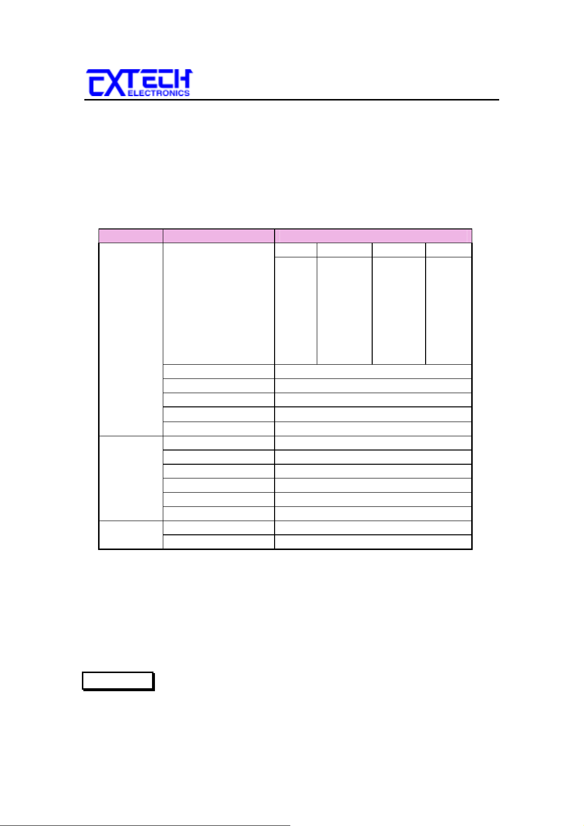
The instrument default settings that appear in memories 1-40 are as follows:
DEFAULTS
5.1
Type Parameter Value
Function Line Step Neutral Reverse Ground
1 Fault Normal Fault
2 Fault Fault Fault
3 Fault Normal Normal
4 Fault Fault Normal
5 Normal Normal Fault
6 Normal Fault Fault
7 Normal Normal Normal
8 Normal Fault Normal
Probe G-L
MD Circuit C (IEC 601)
Connect Step 1-7 = ON; Step 8 = OFF
Trip
0 µA
Delay 1.0s
Setup PLC Remote OFF
Contrast 5
Volume 5
Address (GPIB only) 5
Fail Stop ON
Single Step OFF
Calibration Password 0
Memory Lock ON
5.2 QUICK START INSTRUCTIONS CONT. :
Unpack the instrument from its special shipping container. Be sure to save all
5.2.1
packaging materials in case you need to return it to the factory for service.
Locate a suitable testing area and be sure you have read all safety instructions for
5.2.2
the operation of the instrument and suggestions on the test area set-up
WARNING
instrument to it.
in the Safety section. Locate a three prong grounded outlet. Be sure
the outlet has been tested for proper wiring before connecting the
20
Page 27
GENERAL SETUP PROCEDURES
Check to be sure the correct input line voltage has been selected on the rear panel.
5.2.3
Either 115 volts AC or 230 volts AC. Connect the power input plug
CAUTION
into its socket on the rear panel of the instrument. Connect the male
end of the plug to the outlet receptacle. Please be sure that the safety
ground on the power line cord is not defeated and that you are
connecting to a grounded power source.
Connect the appropriate test leads to the device under test (DUT) or test fixture.
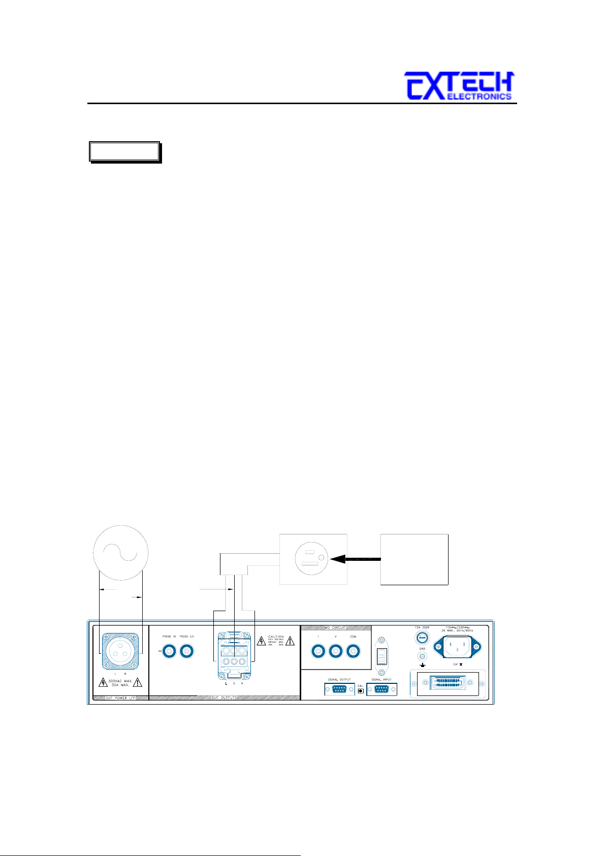
5.2.4
Connect the DUT power input to a AC Power Source that will provide line power
to the DUT. The Power Source must be an unbalanced single phase supply. This
means that there is only one HOT or LINE conductor and the other conductor of
the power source must be at low voltage reference potential.
Be sure that the hot
lead of the power source is connected to the L (line) terminal and the
reference or low voltage lead is connected to the N (neutral) terminal.
!!! To protect the safe of operator, please use Extech AC Power Source or Isolated
Transformer to be the power of DUT.
onnect the adapter box to the DUT output connector on the rear panel. Plug the
C
three prong line cord of the DUT into the adapter box. Be sure to connect the
safety ground to a suitable known good ground before energizing this instrument.
The DUT is now connected properly to perform the Line Leakage test that is
configured into memory. The Line Leakage Tester will measure leakage currents
in series with the ground lead of the DUT as indicated by the G-L probe
configuration on the LCD display. The
G-L configuration is known as the Earth Leakage test.
AC POWER
SOURCE
LINE
NEUTRAL
EARTH
GROUND
LINE
NEUTRAL
ADAPTER BOX
21
LINE
CORD
DUT
Page 28

GENERAL SETUP PROCEDURES
5.2.5
Turn on the POWER switch located on the lower left hand side of the front panel.
Upon powering up the instrument, all LEDs on the front panel will be lit for visual
inspection. If the instrument defaults parameters are not acceptable, refer to the
OPERATION section for detailed instructions on setting up testing parameters.
DO NOT TOUCH THE DEVICE UNDER TEST ONCE THE TEST
WARNING
Check your connections to be sure they are making good contact. Clear the test
5.2.6
HAS BEEN STARTED.
station/area of debris and ask any unnecessary personnel to leave the area.To
initiate the test press the GREEN test button on the front panel. This is a
momentary button and does not need to be held in the pressed position during the
test. The instrument will then cycle ON and begin the automated test sequence
using the defaults. As the test sequence proceeds, you will hear relays clicking
inside the Line Leakage Tester and will observe the three LEDs (Neutral, Reverse
and Ground) to the left of the LCD display turning on and off to indicate the
different line configurations. A fault condition is indicated when the LED is on.
When the LED is off the connection is in a normal state. If a failure occurs you
will hear an audible alarm and see the red failure indicator light up. To stop the
alarm you must press the RED button marked “RESET.” This will silence the
alarm, clear the red fail light, and reset the instrument to begin another test.
This RESET button may also be used to quickly ABORT a test and cut off the
power to the DUT. When VOLTAGE is present a RED TEST indicator located in
the lower right side of the front panel near the probe connectors will illuminate
until the VOLTAGE is shut OFF. If the device under test PASSED the test then
no audible alarm will sound. You will hear a brief BEEP to let you know the item
was successfully tested and it PASSED. In the case of a FAIL condition the
instrument will provide a memory of the test results on the display, that will
remain until the next test is initiated. Pressing the RESET button will prepare the
instrument for the next test but will not clear the display until the next test is
started or another reset is executed.
22
Page 29
GENERAL SETUP PROCEDURES
CHAPTER 6 : General Setup Procedures
6.1 Password Setting
Press and hold the SETUP key while power on the instrument, the program will
enter the Password setting mode. The display will show:
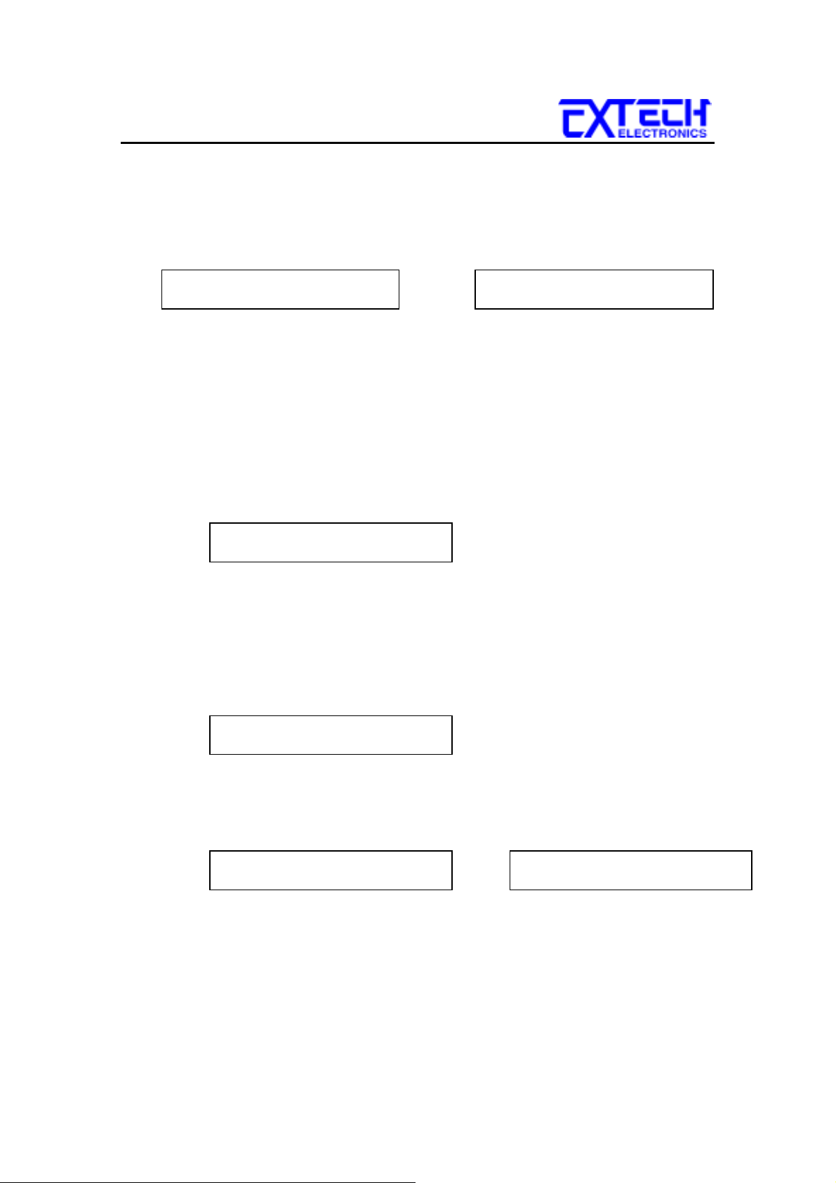
Password = 0
Range : 0 - 9 9 9 9
The Password can be any four (4) digit number. If the Password is set to 0, the
keyboard lock out will be selected by the LOCK key on the front panel without a
Password. The Password default is preset to 0 at the factory. The password will be
saved automatically when the ENTER key is pressed and the instrument will return
to normal operation.
Key Lock
6.2
Press the LOCK key. If the Password is Enabled, the display will show:
Password = _
Range : 0 - 9 9 9 9
Use the Numeric Keys to enter the password and then press the ENTER key. The
program will switch the Key Lock function from LOCK to UNLOCK or UNLOCK
to LOCK mode and advance the program to operation mode automatically. If the
wrong password is entered, the program will give a warning beep and the display
will momentarily show ERROR and then return to the previous screen to allow a
new password entry.
Password = ERROR
Range : 0 - 9 9 9 9
Press the EXIT key to return to the operation mode.
If the Password is Disabled (Password is set 0), the display will show:
Key Lock = O N
ENTER to select
Use the ENTER key to select the Key Lock mode, then press the EXIT key. The
program will switch the Key Lock function from LOCK to UNLOCK or UNLOCK
to LOCK mode and advance the program to the operation mode automatically.
or Password = X X X X
Range : 0 - 9 9 9 9
or Key Lock = O F F
ENTER to select
23
Page 30
GENERAL SETUP PROCEDURES
If the Memory Lock function is set to ON, the Memory selection Menu will be
disabled when in the Lock Mode. If the Memory Lock is set to OFF, the Memory
selection Menu will be enabled when in the Lock Mode. Different memories can be
recalled but the test parameters or steps cannot be changed. The Memory Lock
default is preset to ON at the factory. Please refer to the System Parameter Setup
section to set the Memory Lock mode.
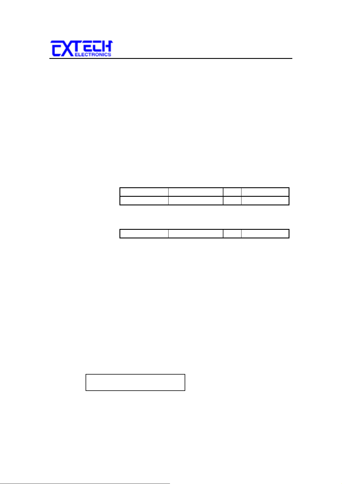
6.3 Memory Configuration
Each memory location contains 8 separate steps which can be connected
sequentially to the next consecutive step. The following memory map illustrates
the separate locations for each step within each memory.
Memory map
Memory 0 Step 1 Step 2
Memory 1 Step 1 Step 2
.
.
.
Memory 9 Step 1 Step 2
. . . .
. . . .
. . . .
Step 8
Step 8
Step 8
6.4 Memory Program
Press the NUMERIC Keys 0-9 to enter the Memory location number. The program
will recall the test parameters stored in this location and the instrument will
respond with a short beep tone.
6.5 Step
Press the STEP key, the display will show the test parameters selected for that step.
Pressing the step key again will advance to the next step in sequence with step 1
following step 8.
Note: When the steps have been interconnected you will see an underbar character
on the display just after the step number. This indicates that the step after the active
step will run immediately after the active step is completed. The display will show:
XXX.X s A XXX.X V
M5-1_ G-L XXX.X µA
24
Page 31
TEST PARAMETER SETUP PROCEDURES
CHAPTER 7 : Test Parameter Setup Procedures
Before going to setup the Test Parameters, make sure that the key lock function is set to
Unlock mode, then follow this procedures to setup the Test Parameters.
7.1 High Trip
The High current trip limit is used to program the maximum allowable leakage
current limit for each configuration that has been selected for each step.
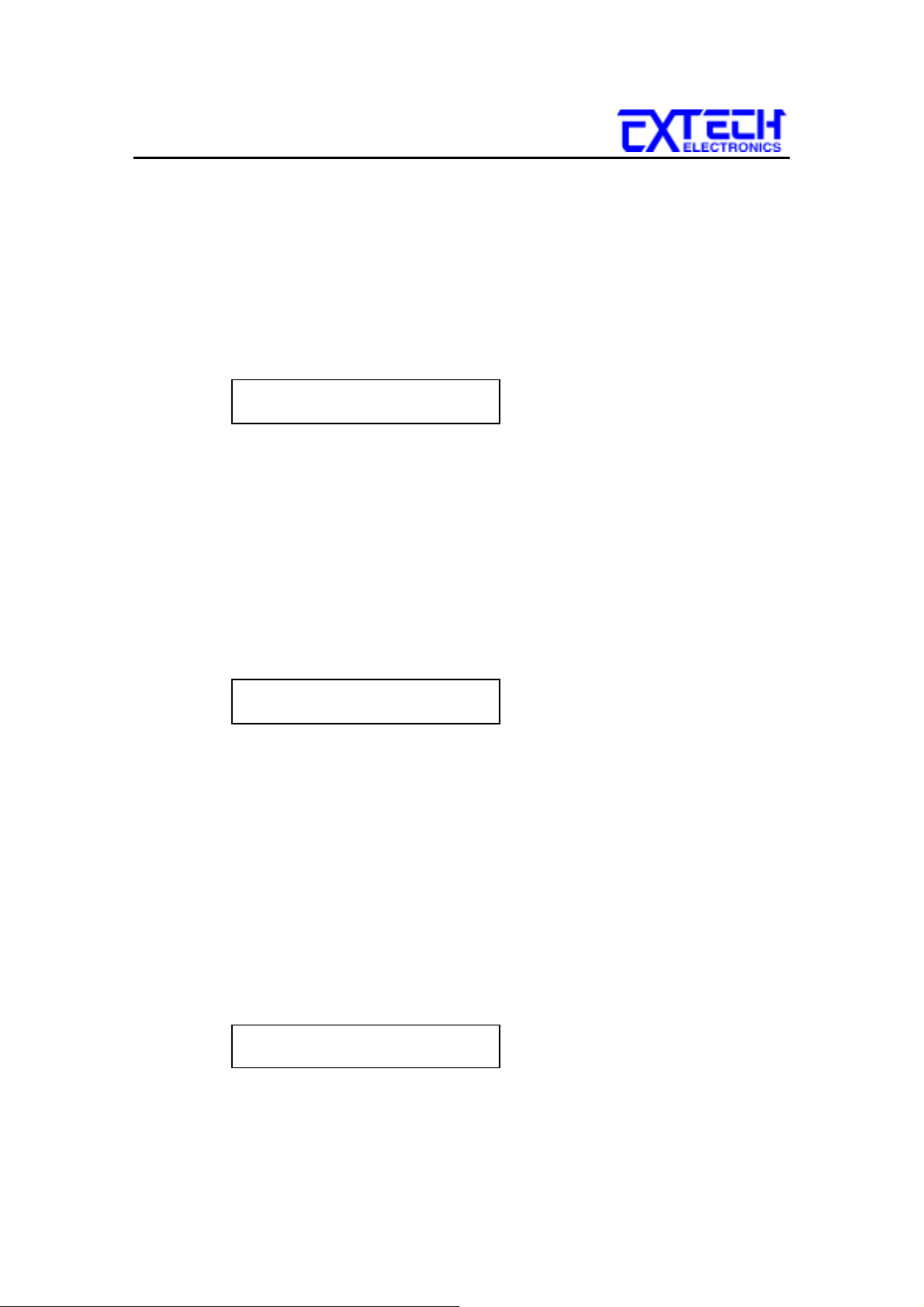
Press the TRIP key, the display will show:
HI-Trip: 1000 µA
Range: 0, 1 - 6000
Use the Numeric Keys to enter the trip current value, and then press the ENTER
key. The program will store this value and advance to the LO-Trip parameter
automatically. When the trip current is set to 0 µA the High current trip limit will
be disabled.
Low Trip
7.2
The Low current trip limit is used to program the minimum allowable leakage
current limit for each configuration that has been selected for each step.
Press the TRIP key twice, the display will show:
LO-Trip: 1000 µA
Range: 0, 1 - 6000
Use the Numeric Keys to enter the trip current value, and then press the ENTER
key. The program will store this value and advance to the HI-Trip parameter
automatically. When the trip current is set to 0 µA the Low current trip limit will
be disabled. Press the EXIT key to return to the operational mode.
7.3 Delay Time
The Delay Time setting is used to program the amount of time that may be needed
to delay the trip current detectors until the DUT has reach proper operating
conditions. The trip current judgment is activated at the end of the Delay Time.
The instrument will not indicate that the Trip Current limit has been exceeded until
the Delay Time period has expired. Press the DELAY key, the display will show:
Delay 2.5 s
Range 0, 1-999.9
Use the Numeric Keys to enter the Delay Time value, and then press the ENTER
key. The program will store this value and return to the operation mode
automatically.
25
Page 32
TEST PARAMETER SETUP PROCEDURES
A
A
7.4 Line Configuration
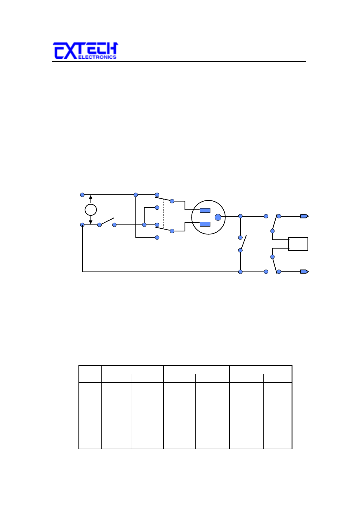
The LINE configuration is determined by the relays S1, S2 and S3 shown in figure 1
below. The three relays can be configured into eight possible combinations. The
three relays are represented on the front panel by the three LEDs (NEUTRAL,
REVERSE, and GROUND) to the left of the display. S1 relay is represented as
NEUTRAL. S2 relay is represented as REVERSE. S3 relay is represented as
GROUND. When an LED is ON it indicates that the relay is in a faulted condition
when the LED is OFF it indicates that the relay is in a normal or good operating
condition. For example, when the NEUTRAL or GROUND LED is ON it indicates
that the relay is opened and represents a fault in the line input wiring. When the
REVERSE LED is ON this represents that the relay is in position B indicating that
the Line and Neutral conductors are reversed at the DUT power outputs shown as the
DUT power
A
receptacle
DUT
power
input
V
B
S2
SH
B
S1
S3
B
SL
Figure 1
DUT power receptacle in figure 1.
To change the Line configuration press the LINE key. The line configuration will
change each time the key is pressed in a sequential order represented in the table
below.
Step NEUTRAL REVERSE GROUND
Relay LED Relay LED Relay LED
1 Open ON A OFF Open ON
2 Open ON B ON Open ON
3 Open ON A OFF Closed OFF
4 Open ON B ON Closed OFF
5 Closed OFF A OFF Open ON
6 Closed OFF B ON Open ON
7 Closed OFF A OFF Closed OFF
8 Closed OFF B ON Closed OFF
Probe HI
MD
Probe LO
26
Page 33
TEST PARAMETER SETUP PROCEDURES
When the LEDs represent the desired line configuration the test is ready to start.
No other keystrokes are necessary. The line configuration settings are automatically
saved in memory.
7.5 Probe Configuration
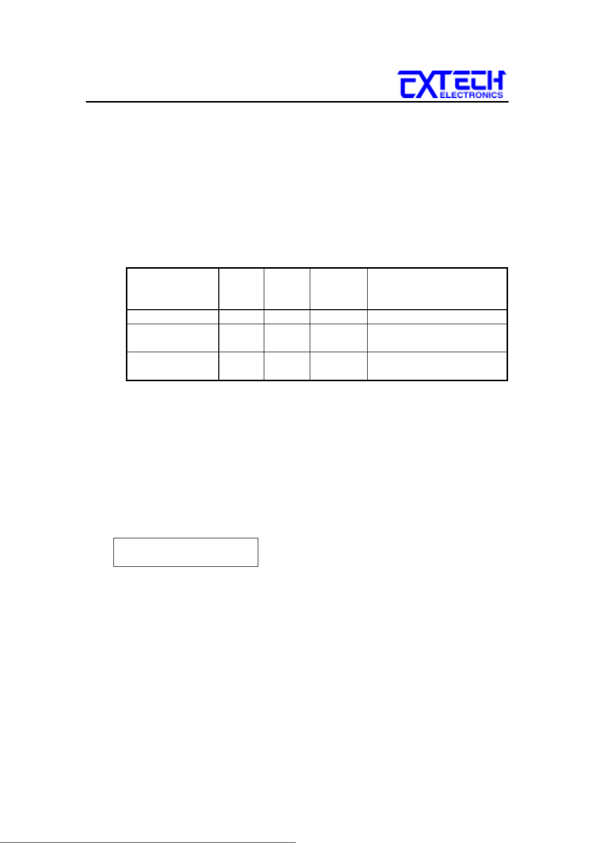
The Probe configuration is controlled by the relays SH and SL in Figure 1 of the
previous section 2.3. These two relays configure the current measuring device into
three possible positions. The three positions are described in the table below.
Measuring
Device Position
SH SL Display
Agency Test Application
Indicatio
n
Ground to Line A A G-L Earth Leakage
Probe HI to Line B A PH-L Enclosure Leakage or
Patient Leakage
Probe-HI to
Probe-LO
B B PH-PL External Applied Part or
Surface to Surface Leakage
G-L indicates the MD is connected to measure the leakage current in the earth ground
conductor in the line cord back to the system neutral, an EARTH LEAKAGE TEST.
-L indicates the MD is connected between the PROBE HI (PH) terminal on the
P
H
instrument, which should be connected to the ENCLOSURE of the DUT and the
system neutral. This is known as an ENCLOSURE LEAKAGE TEST. P
the MD is connected between the PROBE HI (P
) and the PROBE LO (PL) terminals
H
H-PL
indicates
on the instrument which allow the operator to connect the MD between applied parts.
The LCD display will indicate the Probe configuration in the center of the second
line. The ground to line configuration will be indicated as follows:
1 . 0 s D 110.2V
M1-1_ G-L 2500µA
To change the Probe configuration press the PROBE key. The Probe configuration
will change each time the key is pressed, in sequential order. When the display
indicates the desired Probe configuration, the test is ready to start. No other key
strokes are necessary to finish the configuration. The Probe configuration settings
are automatically saved into memory.
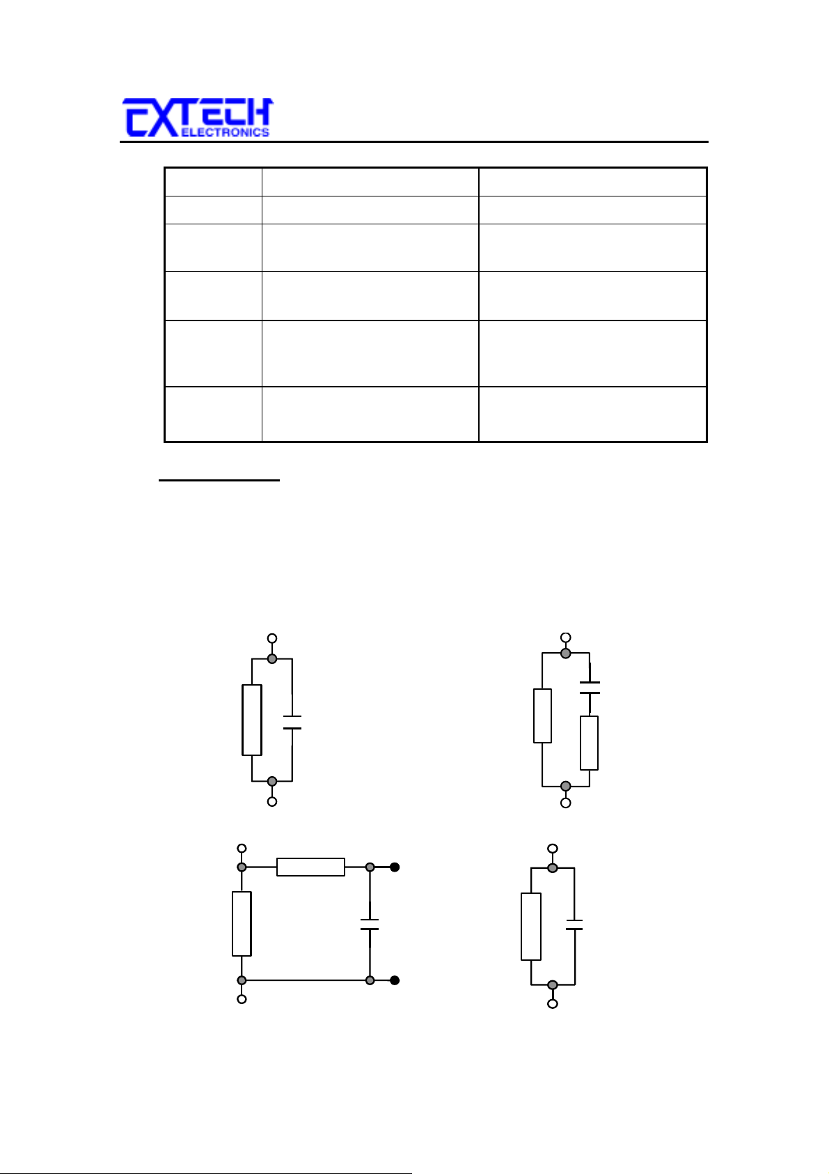
7.6 Measuring Device
The Measuring Device is the human body impedance circuit that is specified in the
agency specification for leakage current tests. The following table indicates the
measuring device letter designation used by 7611 and the appropriate agency
standard that it correlates to.
27
Page 34
TEST PARAMETER SETUP PROCEDURES
Designation Agency Specification Application
A
B
UL544 Non Patient equipment Medical Equipment
UL 544 Patient care
Medical Equipment
equipment
C
IEC601-1、UL2601
、
Medical Equipment
EN60601-1
D
UL 1563 Electric Spas,
Equipment Assemblies and
Associated Equipment
E
IEC 1010, UL 3101.
IEC 950, UL 1950, EN 60950
Laboratory Equipment.
Information Technology.
Circuit Diagrams
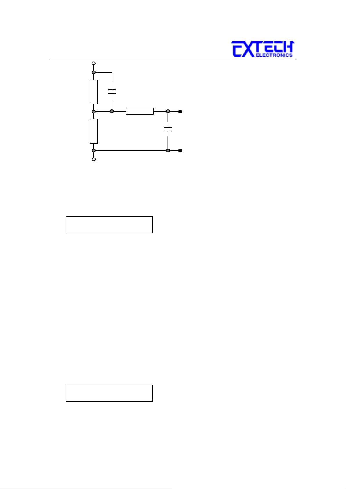
The following diagrams show the equivalent circuit of the measuring devices.
Leakage current readings are generated by measuring the voltage drop across these
networks and dividing by the equivalent DC resistance. The volt meter is placed
across the entire network of measuring device A, B and D, but is placed across the
points indicated by the solid black dots on measuring device C and E, as specified
in the agency specifications that apply to the particular measuring device.
MD =A
MD = B
0.15µF
1K
1.5K
0.15uF
Ω
10.2
MD = C
10K
1K
0.015uF
MD = D
500
Ω
0.45µF
28
Ω
Page 35
TEST PARAMETER SETUP PROCEDURES
1.5K
Ω
0.22µF
10K
Ω
500
Ω
0.022µF
MD = E
The display will indicate the Measuring Device in the center of the first line of the
LCD display. The Measuring Device is indicated with letters A through F.
Measuring Device A will be displayed as follows:
1 . 0 s A 110.2V
M1-1
_
G-L 2500µA
To change the Measuring Device, press the MD CIRCUIT key. The Measuring
Device will change each time the key is pressed, in sequential order. When the
display indicates the desired Measuring Device, the test is ready to start. No other
key strokes are necessary to save the configuration. The Measuring Device settings
are automatically saved into memory.
7.7 Connect Configuration
The connect feature of the Line Leakage Tester allows the instrument to link the
individual STEP configurations together into a sequence of tests. Each of the eight
steps within a memory location can be linked together, as well as linking the last
step of a memory to the first step of the next memory. Therefore the possibility
exists to link 400 different configurations together as one test sequence.
To change the connect configuration for an individual step, press the CONNECT
key. An underbar character will be present next to the Step number when the
connect feature is turned ON. The display will indicate the connection as follows:
1 . 0 s A 110.2V
M1-1
By pressing the CONNECT key again, the underbar character will be removed and
replaced with a blank space and Step connection will be turned OFF.
_
G-L 2500µA
29
Page 36
SYSTEM PARAMETER SETUP
CHAPTER 8 : System Parameter Setup
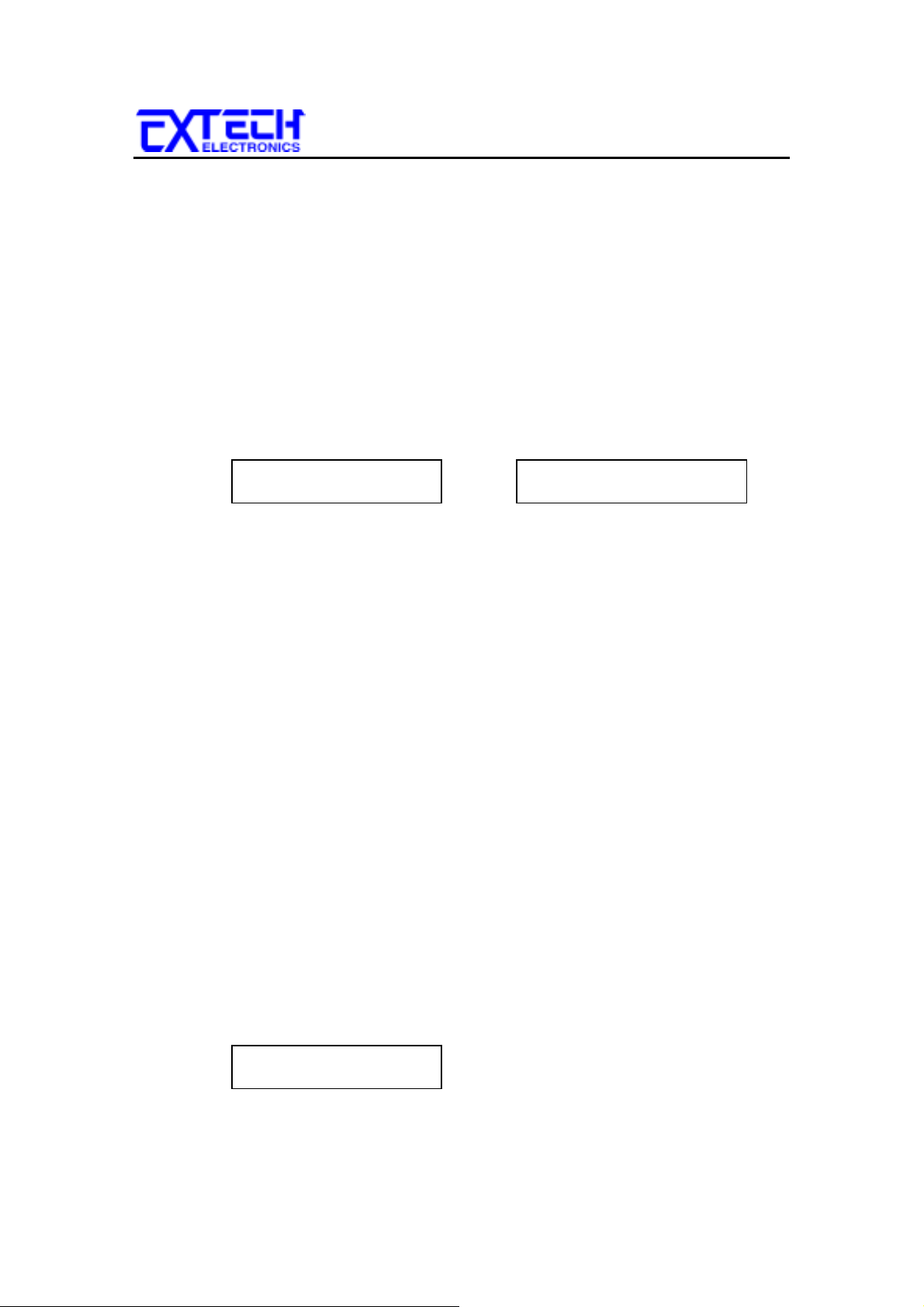
Use the SETUP key to progress through the menu of System Parameters. Successive key
presses will advance the menu forward. The sequential forward menu items are PLC
Remote, Contrast, Volume, Address, Fail Stop, Single Step, and Memory Lock.
The setting of system parameters affect the operating conditions of the instrument and are
separate from the functional settings. The system settings are also global and are not
specific to any memory location.
8.1 PLC Remote
Press the SETUP key to advance to the PLC Remote parameter. The display will
show:
PLC Remote = ON
ENTER to select
or PLC Remote = OFF
ENTER to select
Use the ENTER key to select the PLC Remote Control mode.
After selecting PLC Remote mode, press the SETUP key to advance to the address
setting if the GPIB interface card is installed on this instrument. If this instrument
does not have the GPIB interface card, the program will advance to the contrast
setting, or press the EXIT key to exit from the PLC Remote selection to the
operation mode. The instrument will store the selection of PLC Remote
automatically.
If the Remote Control is set to ON, the test function will be controlled by the
Remote Control via the remote connectors located on the rear panel. The TEST
button on the front panel is disabled but the RESET button is still enabled.
The remote Memory Program recall functions can be performed only when the PLC
Remote is set ON. In addition, when the PLC remote is set to ON the remote TEST
signal input is active while in the Bus Remote Mode.
If the Remote Control is set to OFF, the operation of the instrument will be
controlled by the local TEST and RESET buttons on the front panel.
8.2 LCD Contrast
Press the SETUP key to advance the menu to the Contrast parameter. The display
will show:
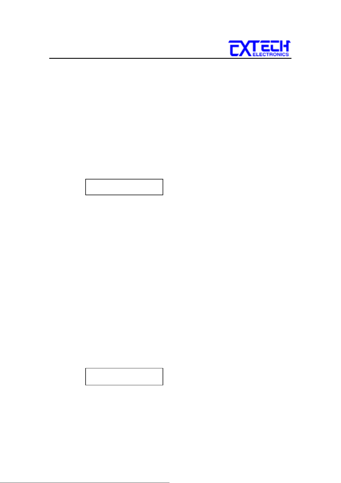
Contrast = X
Range 1-9 9=High
30
Page 37
SYSTEM PARAMETER SETUP
Use the numeric keys to enter the LCD Contrast level. The program will change the
LCD Contrast immediately when the key is pressed, so the setting can be viewed.
Change the LCD Contrast again or press the SETUP or ENTER key to advance to
the Volume setting, or press the EXIT key to exit from the LCD Contrast setting to
the operation mode. The program will store the Contrast setting automatically.
The LCD Contrast range is from 1 - 9, a total of 9 levels. Level 1 is the lowest
contrast and level 9 is the highest contrast.
8.3 Audible Alarm Volume
Press the SETUP key to advance the menu to the Volume parameter. The display
will show:
Volume = X
0-9 0=OFF 9=High
The Audible Alarm Volume range is from 0 - 9, a total of 10 levels. Level 0 is used
to disable the Audible Alarm. Level 1 is the lowest volume and level 9 is the
loudest.
Use the numeric keys to enter the Audible Alarm level. The program will provide a
sample sound for checking immediately when the numeric key is pressed.
Change the Volume again or press the SETUP or ENTER key to forward to address
setting if the GPIB interface card is installed on this instrument. If this instrument
does not have the GPIB interface card, the program will advance to the Fail Stop
selection program, or press the EXIT key to exit from the Audible Alarm setting to
the operation mode. The program will store the Volume setting automatically.
8.4 GPIB Address
If the GPIB interface card is not installed on this instrument, this setup program will
not appear on the setup menu.
Press the SETUP key to advance the menu to the address parameter. The display
will show:
Address = X
Range : 0 - 30
Use the numeric keys to enter the GPIB Address number, then press the ENTER
key. The program will store the address setting automatically and advance to the
Fail Stop selection.
31
Page 38
SYSTEM PARAMETER SETUP
If the wrong address is entered, press the EXIT key to erase last input and return to
previous address. Press the EXIT key second time to exit from the address setting to
the operation mode or press the SETUP key to advance to the Fail Stop selection.
8.5 Fail to Stop/Continue
Press the SETUP key to advance the menu to the Fail Stop parameter. The display
will show:
Fail Stop = ON
ENTER to select
Use the ENTER key to select the mode of Fail Stop.
After the selection of Fail Stop mode, press the SETUP key to advance to the Single
Step selection, or press the EXIT key to exit from the Fail Stop selection to the
operation mode. The Program will store the selection of Fail Stop automatically.
This function is used when multiple steps have been connected. If the Fail Stop
mode is set ON, the test process will stop at the step that fails, or at the end of test
process. When there are unfinished steps to be completed, pressing the TEST button
will continue the test process at the next step. Pressing the RESET button and then
the TEST button will start the test process from the first step.
If the Fail Stop is set to OFF, the instrument will continue to complete the entire
test process even if there were failed steps during the test. The display will show
the results of each step at the end of test process, as follows:
or Fail Stop = OFF
ENTER to select
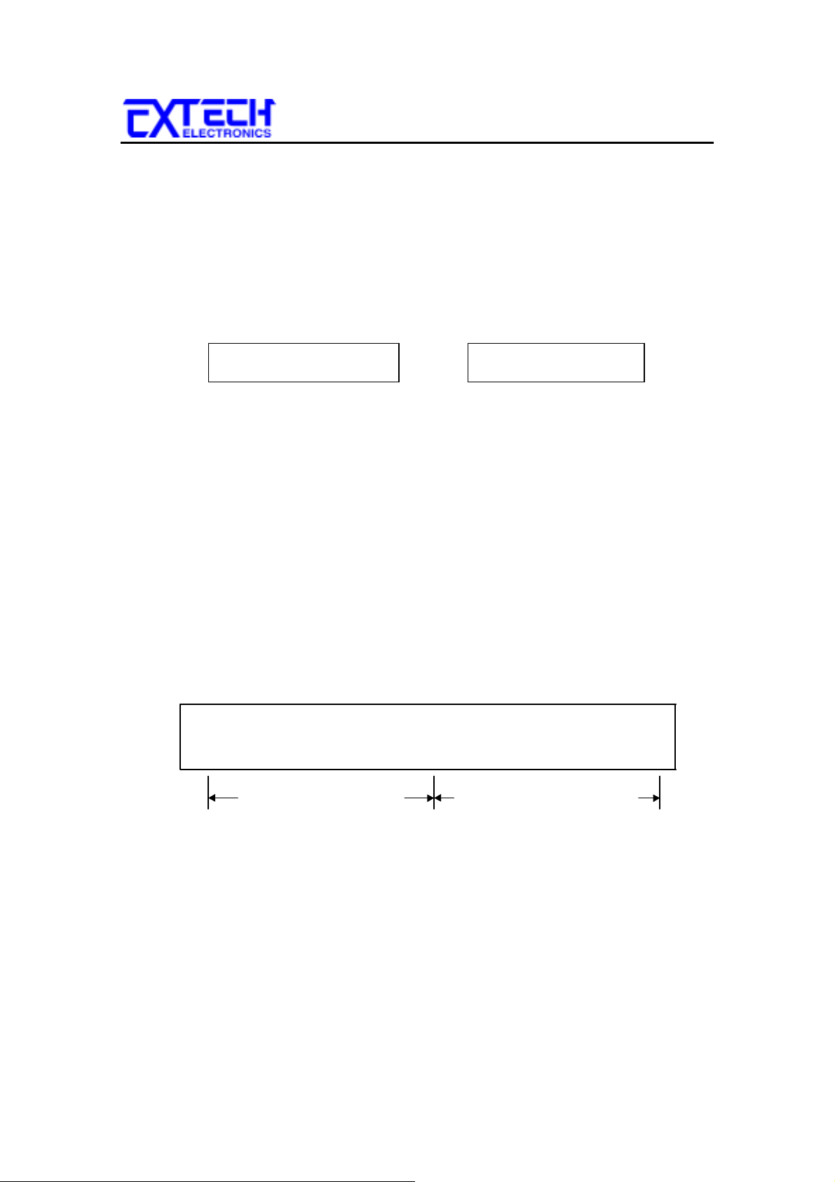
T PFPFPFPFPFPF PFP
S 123456781234567
First Memory Program Second Memor y P r ogr am
The pass fail status is indicated by the letter F (Fail) or P (Pass). The Pass/Fail
status of the first memory Program will show on the left end and the second one
will be on the right. The pass/fail status of the first 16 steps can be displayed. A
maximum of 16 steps will be saved. If more than 16 steps are executed in sequence,
results from those steps greater than 16 cannot be retrieved from memory.
32
Page 39
SYSTEM PARAMETER SETUP
8.6 Single Step
Press the SETUP key to advance the menu to the Single step parameter. The
display will show:
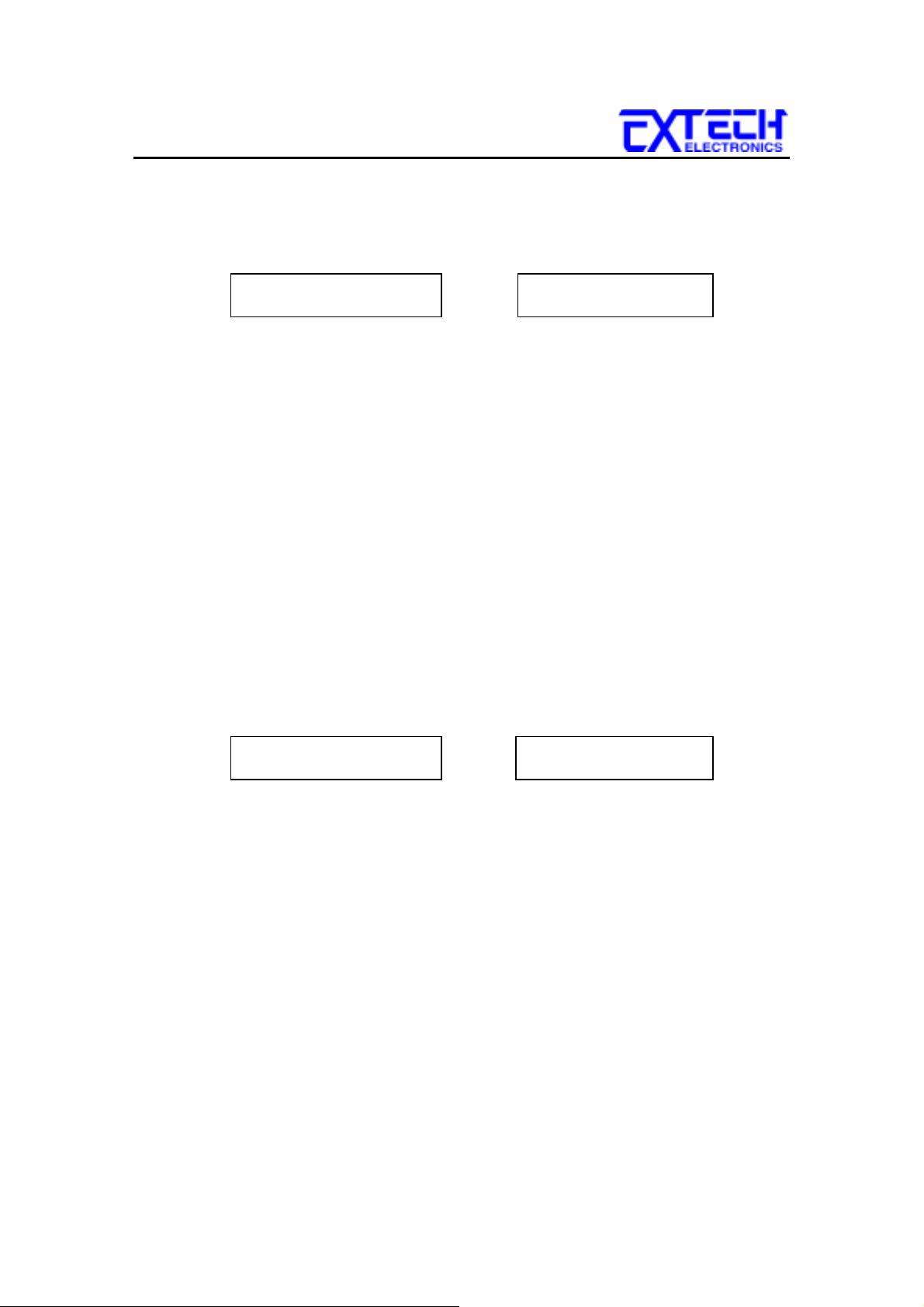
Single Step = ON
ENTER to select
or Single Step = OFF
ENTER to select
Use the ENTER key to select the Single step mode.
After the selection of Single step mode, press the SETUP key to advance to the
Memory Lock selection, or press the EXIT key to exit from the Single step
selection to the operation mode. The Program will store the selection of Single step
automatically.
This function is used to temporarily override the automatic connection feature.
When the single step function is ON the instrument will pause after each step is
completed. To continue the test sequence, press the Test button to execute the next
connected step. Each time the Test button is pressed the next connected step will
execute. The first step of the sequence will execute, when the Test button is
pressed after the last step of the sequence has completed.
8.7 Memory Lock selection
Press the SETUP key, the program will advance to the Memory Lock selection
mode. The display will show:
Memory Lock = O N
ENTER to select
If the Memory Lock is selected ON, the Memory selection Menu will be disabled
when in Lock Mode. If the Memory Lock is selected OFF, the Memory selection
Menu will be enabled when in Lock Mode. Different memories can be recalled but
the test parameters or steps can not be changed. The Memory Lock default is
preset to ON at the factory.
After the selection of Memory Lock mode, press the SETUP key to advance to the
beginning of the menu (PLC Remote), or press the EXIT key to exit from the
Memory Lock selection to the operation mode. The program will store the selection
of Memory Lock automatically.
or Memory Lock = O F F
ENTER to select
33
Page 40
OPERATION PROCEDURE
CHAPTER 9 : Operation Procedure
9.1 Setup
Before the operation of this instrument, make sure that all Test Parameters have
been set properly according to the Test Parameters Setup Procedures. Also check
the system setting of Remote Control, LCD Contrast, Alarm Volume, Fail Stop,
Single Step, and Memory Lock.
The Power Source to the DUT inputs must be an unbalanced
WARNING
user.
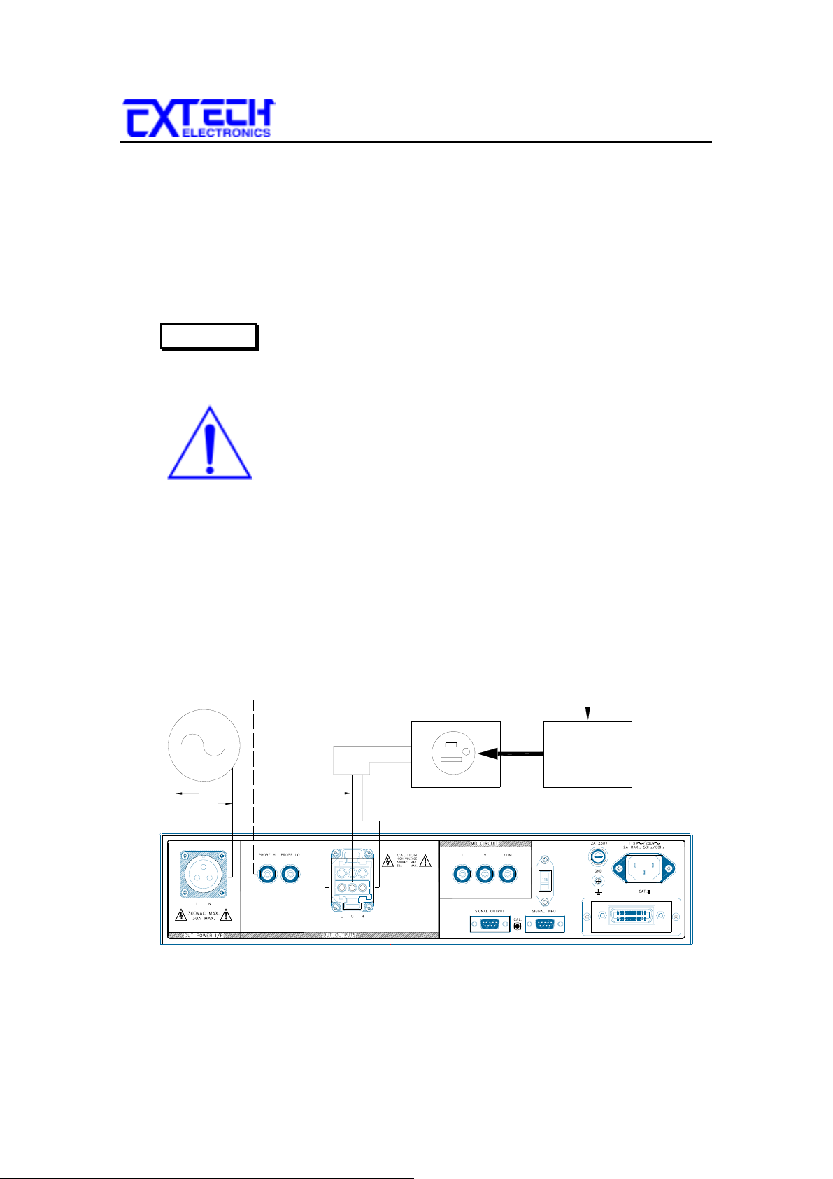
Be sure to connect the appropriate test leads to the device under test (DUT) or test
fixture, as shown in the diagram below. Please be sure to use a Power Source
which has only one line conductor that is of the balanced type as stated previously.
Be sure to connect the safety ground terminal (on the rear panel) to a suitable
known good ground before energizing this instrument.
single phase supply. This means that there is only one HOT or
LINE conductor and the other conductor of the power source
must be at a low voltage reference potential. This low voltage
reference does not need to be physically earth grounded but
should not carry any large voltage potential. The 220 - 240V
US style line power
IS NOT
suitable to be connect to the DUT
inputs. This style of power distribution is a balanced type with
two HOT or LINE conductors.
DO NOT
connect a line
conductor to the N or Neutral terminal of the DUT inputs. This
condition can be very dangerous to the Line Leakage Tester
AC POWER
NEUTRAL
SOURCE
LINE
EARTH
GROUND
LINE
NEUTRAL
ADAPTER BOX
34
DUT CHASSIS
LINE
CORD
DUT
Page 41
OPERATION PROCEDURE
The dotted line at the Probe HI output illustrates the connection for an
ENCLOSURE LEAKAGE TEST required by the agencies. The Probe HI
connection could also be used together with the Probe LO connection to perform
other leakage tests that are not illustrated here.
Check your connections to be sure
they are making good contact. Clear the test station/area of debris and ask any
unnecessary personnel to leave the area.
WARNING
DO NOT TOUCH THE DEVICE UNDER TEST ONCE
THE TEST HAS BEEN STARTED.
9.2 Power Up
Turn on the Input Power Switch. All status LEDs will light up, then the display will
show the Trade Mark, Model Number and Version Number first, as follows:
ARI LINECHECK
510L VER: X.X
The program will then recall the Memory and Step which was last executed.
9.3 Set Mode Screen
The settings screen will show parameter settings of the test that will be performed
and the memory locations that they are stored in. This screen can be accessed after
a test is aborted or after a pass condition by pressing the RESET button or after a
test failure by pressing the RESET button twice. The test result will overwrite the
Delay timer after a test is completed or when a failure occurs. The left side of the
second line always indicates the Memory and Step that has been selected and an
underbar character to the right of the step number indicates that the step has been
connected to the next step in sequence. The display will show the underbar
indicating step 1 is connected to step 2 as follows:
1 . 0 s D 110.2V
M1-1
_
G-L 2500µA
9.4 Reviewing Test Results
The test results from the first 16 tests that are executed can be reviewed by pressing
the Enter/Review key. Successive key presses will continue advancing to the next
result. The results of the last step in the process will be followed by the first step
when scrolling through the results.
35
Page 42

OPERATION PROCEDURE
If four or more memories are connected together (more than an 16 step process)
then only the first 16 steps executed in the process will be stored into the results
memory. The results from the steps executed after the first 16 steps in the process
will not be retrievable. Results can be reviewed at any time before the next test is
executed. All 16 buffers are cleared at the start of the next test cycle.
36
Page 43
LCD DISPLAYED MESSAGES
CHAPTER 10 : LCD Displayed Messages
10.1 Test In Process
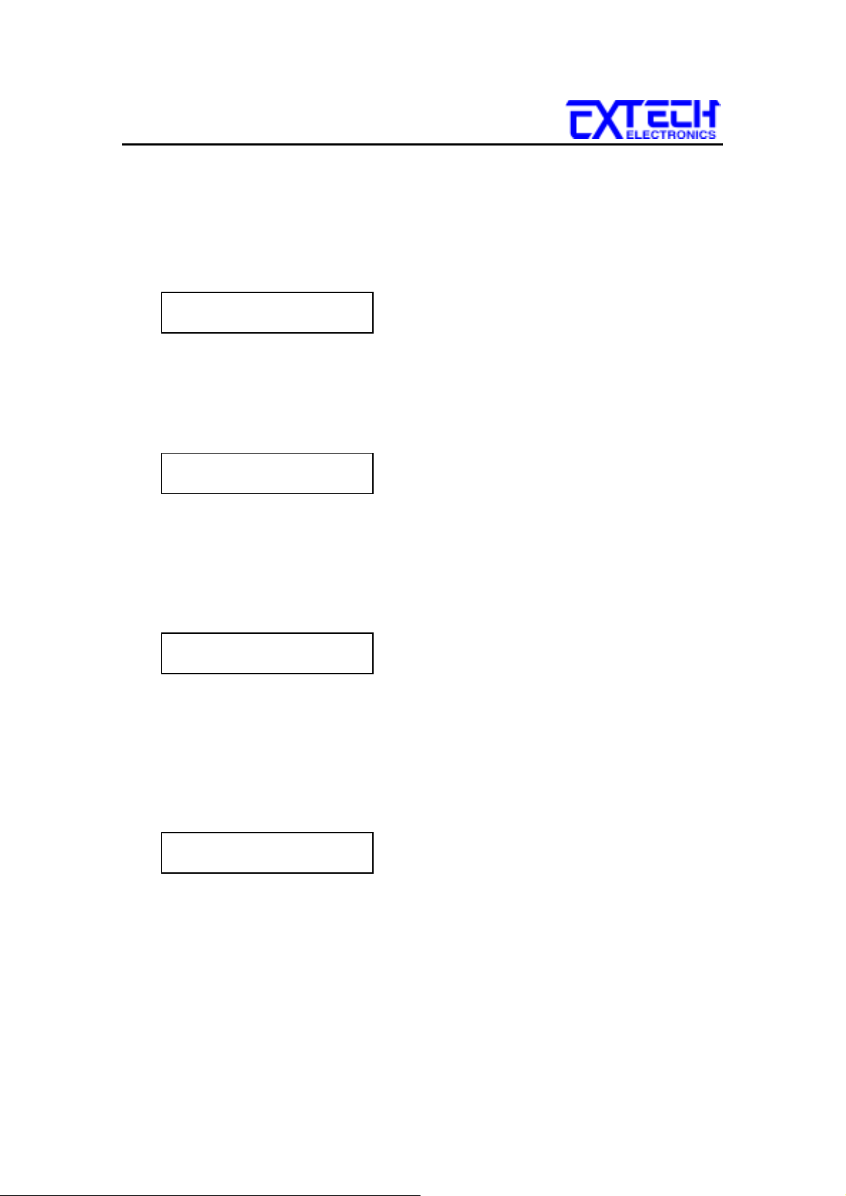
After pressing the test button to initialize the test, the TEST light on the right side
of the instrument will illuminate. The instrument will indicate the test is
processing as follows:
Test 222s 110.2V
M1-1
_
G-L 2500µA
10.2 Abort
If the RESET button is pressed during the test cycle the test will be aborted and
the display indicate that the test has been aborted as follows:
A b o r t D 110.2V
M1-1
_
G-L 2500µA
10.3 Pass
When the test cycle has completed successfully without detecting any failures, you
will hear a short audible beep to let you know the test has completed successfully.
The display will also indicate that the test has passed as follows:
P a s s D 110.2V
M1-1
_
G-L 2500µA
10.4 High Limit Failure
If the leakage current of the item under test exceeds the HI-Trip setting, the unit
will indicate a failure at the end of the delay time by illuminating the FAIL
indicator and activating the alarm. All relays will be deactivated to disable
voltage to the DUT. The display will indicate a high limit failure as follows:
H I - F a i l D 110.2V
M1-1
To clear the failure light and alarm, press the RESET button. The alarm and light
will be turned off but the display will continue to indicate the type of failure until
a second reset is activated.
_
G-L 2500µA
37
Page 44
LCD DISPLAYED MESSAGES
V
A
A
10.5 Low Limit Failure
If the leakage current of the item under test less than the LO-Trip setting, the unit
will indicate a failure at the end of the delay time by illuminating the FAIL
indicator and activating the alarm. All relays will be deactivated to disable
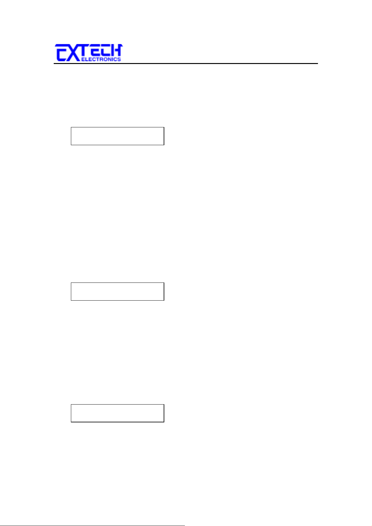
voltage to the DUT. The display will indicate a low limit failure as follows:
L O - F a i l D 110.2V
M1-1
_
G-L 2500µA
To clear the failure light and alarm, press the RESET button. The alarm and light
will be turned off but the display will continue to indicate the type of failure until
a second reset is activated.
10.6 Measuring Device Overload
This failure condition will interrupt the delay cycle. The delay time will not be
completed because the measuring device overload failure is a failure that requires
an immediate shutdown.
If the probes are applied to voltage that exceeds the maximum limit specified, the
unit will indicate failure by illuminating the FAIL indicator and activating the
alarm. All relays will be deactivated to disable voltage to the DUT. The display
will indicate measuring device overload failure as follows:
MD-OVLD D 110.2
M1-1
_
G-L >6000µ
10.7 Line Current Overload
This failure condition will interrupt the delay cycle. The delay time will not be
completed because the line over-current failure is a failure that requires an
immediate shutdown.
If the line current of the item under test exceeds the maximum limit of DUT
current, the unit will indicate failure by illuminating the FAIL indicator and
activating the alarm. All relays will be deactivated to disable voltage to the DUT.
The display will indicate a line over-current failure as follows:
Line OC D 110.2V
M1-1
_
G-L 2500
µ
38
Page 45
LCD DISPLAYED MESSAGES
10.8 Line Voltage Overload
This failure condition will interrupt the delay cycle. The delay time will not be
completed because the line over-voltage failure is a failure that requires an
immediate shutdown.
If the line voltage of the DUT input exceeds the maximum limit of DUT voltage,
the unit will indicate failure by illuminating the FAIL indicator and activating the
alarm. All relays will be deactivated to disable voltage to the DUT. The display
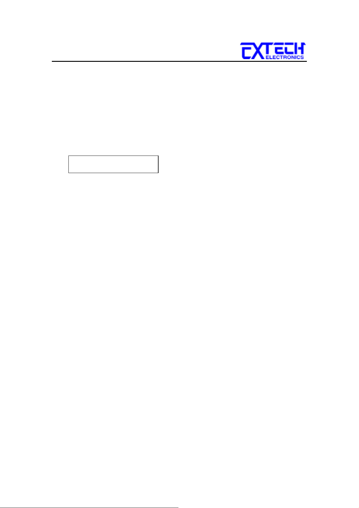
will indicate a line over-voltage failure as follows:
Line OV D >300V
M1-1
_
G-L 2500µA
39
Page 46
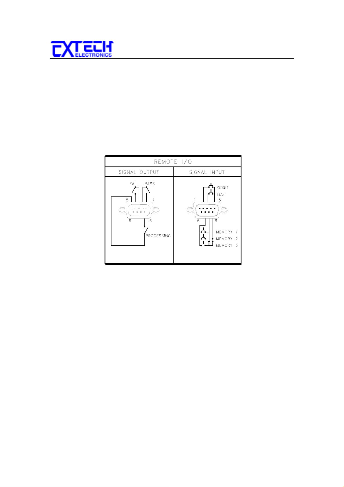
RS232 & GPIB INTERFACE
CHAPTER 11 : REMOTE OPERATION
Two 9 pin “D” type connectors are mounted on the rear panel which provide REMOTEI/O control and information. These connectors mate with standard 9 pin D-subminiature
connector provided by the user. The output mates to a male (plug) connector while the
input mates to a female (receptacle) connector. For best performance a shielded cable
should be used. To avoid ground loops the shield should not be grounded at both ends of
the cable.
11.1 Remote Interface Rear Panel
11.2 Signal Outputs on Remote I/O
The rear panel connector provides three output signals to remotely monitor PASS,
FAIL, and PROCESSING conditions. The monitoring signals are provided by
three normally open internal relays that switch on to indicate the current condition
of the tester. These are normally open free contacts and will not provide any
voltage or current. The ratings of the contacts are 1A / 250 VAC ( 0.5 ADC ). The
signal outputs are provided on the 9 pin female type D connector. Below is a
listing that indicates what conditions activate each pin. When a terminal becomes
active the relay closes thereby allowing the external voltage to operate an external
device.
Pins 1 and 2 provide the PASS signal.
Pins 3 and 4 provide the FAIL signal.
Pins 5 and 6 provide the PROCESSING signal.
The following describes how the relays operate for each test condition.
PROCESSING - The relay contact closes the connection between pin (5) and pin
(6) while the instrument is performing a test. The connection is opened at the end
of the test.
40
Page 47
REMOTE OPERATION
PASS - The relay contact closes the connection between pin (1) and pin (2) after
detecting that the item under test passed all tests. The connection is opened when
the next test is initiated or the reset function is activated.
FAIL - The relay contact closes the connection between pin (3) and pin (4) after
detecting that the item under test failed any test. The connection is opened when
the next test is initiated or the reset function activated.
11.3 Signal Inputs of Remote I/O and Memory Programs
The Line Leakage Tester remote connector enables remote operation of the TEST
and RESET functions or allows the operator to select one of three preprogrammed tests. A signal input is also provided to indicate that a Withstand test
is processing. When the remote function is (ON) the test switch on the front panel
will be disabled to prevent a test from being activated through the test switch. A
normally open momentary switch can then be wired across pins 3 and 5 to allow
remote operation of the TEST function. A normally open momentary switch can
also be wired across pins 2 and 5 which allows remote operation of the RESET
function. For safety, the front panel RESET switch remains active even when a
remote reset switch is connected so that high voltage can be shut down from
either location.
The Line Leakage Tester also allows access to three MEMORY PROGRAMS
through the remote control connector. This gives the user the capability to
quickly change parameters and initiate a test remotely. The Line Leakage Tester
basically operates in a PLC mode by responding to simple switch or relay contact
closures. The built in memory programs of the instrument are used to accomplish
this. Three internal memory programs can be accessed. By connecting terminals
7, 8 and 9 in different combinations the user can select the correct memory
program.
ACTIVATING MEMORY PROGRAM FUNCTIONS THROUGH THE
REMOTE CONNECTOR, SELECTS THE PROGRAM AND STARTS
WARNING
CAUTION
MEMORY 1 - Momentarily connecting terminal 7 to 8 signals the instrument to
immediately begin the test program that is stored in memory 1.
MEMORY 2 - Momentarily connecting terminal 7 to 9 signals the instrument to
immediately begin the test program that is stored in memory 2.
MEMORY 3 - Momentarily connecting terminal 7 to terminals 8 and 9 signals the
instrument to immediately begin the test program that is stored in memory 3.
THE TEST WHICH IS PRE-PROGRAMMED INTO THAT MEMORY.
DO NOT CONNECT VOLTAGE OR CURRENT TO THE SIGNAL
INPUTS, THIS COULD RESULT IN DAMAGE TO THE
CONTROL CIRCUITRY.
41
Page 48

RS232 & GPIB INTERFACE
CHAPTER 12 : RS232 & GPIB INTERFACE
This section provides information on the proper use and configuration of bus remote
interface. The GPIB (IEEE-488) remote interface is standard on model 510L but the RS232 interface option can be substituted for the GPIB interface. The RS-232 interface also
uses the same command list as the GPIB with the exception of the SRQ functions. Please
refer to the Option section of this manual for details on the 7611 options.
12.1 GPIB Messages
There are typically two types of messages that GPIB devices use to communicate
with other interconnected GPIB devices;
often called commands or command messages and Device
Interface messages
dependent messages often called data or data messages.
Data Messages
measurement results. Command Messages perform functions such as initializing
the bus and addressing and unaddressing devices.
:
contain information such as programming instructions or
:
12.2 Functions
A GPIB device can be a Listener, Talker and/or Controller. A Talker sends data
messages to one or more Listeners, which receive data. A Controller manages the
information flow on the GPIB by sending commands to all devices. The GPIB
bus is much like a computer bus except a computer has circuit cards connected via
a backplane and the GPIB has stand alone devices connected via a cable.
12.3 Signals and Lines
The GPIB consists of 16 signal lines and 8 ground-return or shield drain lines.
The 16 signal lines are grouped into 8 data lines, 3 handshake lines and 5 interface
management lines.
Data Lines: The eight data lines, DI01 through DI08 carry data and command
messages. The 7-bit ASCII or ISO code set is used and the eighth bit DI08 is unused.
Handshake Lines: The transfer of message bytes between devices is done via
three asynchronously control lines. Referred to as three-wire interlocked
handshake. This guarantees that message bytes on the data lines are sent and
received without transmission error.
NRFD
receive a message byte.
NDAC
message byte.
(not ready for data) indicates when a device is ready or not ready to
(not data accepted) indicates when a device has or has not accepted a
42
Page 49

RS232 & GPIB INTERFACE
(data valid) tells when the signals on the data lines are stable (valid) and can
DAV
be accepted safely by devices.
Interface Management Lines: Five lines are used to manage the flow of
information across the interface.
(attention) ATN is driven true by the controller when it uses the data lines
ATN
to send commands, and drivers ATN false when a Talker can send data messages.
(interface clear) IFC is driven by the system controller to initialize the bus
IFC
and become CIC.
(remote enable) The REN line is driven by the controller which is used to
REN
place devices in remote or local program mode.
(service request) The SRQ line can be driven by any device to
SRQ
asynchronously request service from the Controller.
(end or identify) This line has two purposes- the Talker uses this line to
EOI
mark the end of a message string, and the Controller uses it to tell devices to
identify their response in a parallel poll.
GPIB Connector
12.4
Connection is usually accomplished with a 24-conductor cable with a plug on one
end and a connector at the other end. Devices may be connected in a linear, star
or a combination configuration.
The standard connector is the Amphenol or Cinch Series 57 Microribbon or AMP
CHAMP type. The GPIB uses negative logic with standard transistor-transistor
logic (TTL) levels. When DAV is true, for example, it is a TTL low level (≤ 0/8
V), and when DAV is false, it is a TTL high level (≥ 2.0 V).
Restrictions and Limitations on the GPIB
A maximum separation of 4 m between any two devices and an average
separation of 2 m over the entire bus. A maximum total cable length of 20 m.
No more than 15 device loads connected to each bus, with no less than two-thirds
powered on.
A bus extender which is available from numerous manufacturers is
Note:
available to overcome these limitations.
43
Page 50
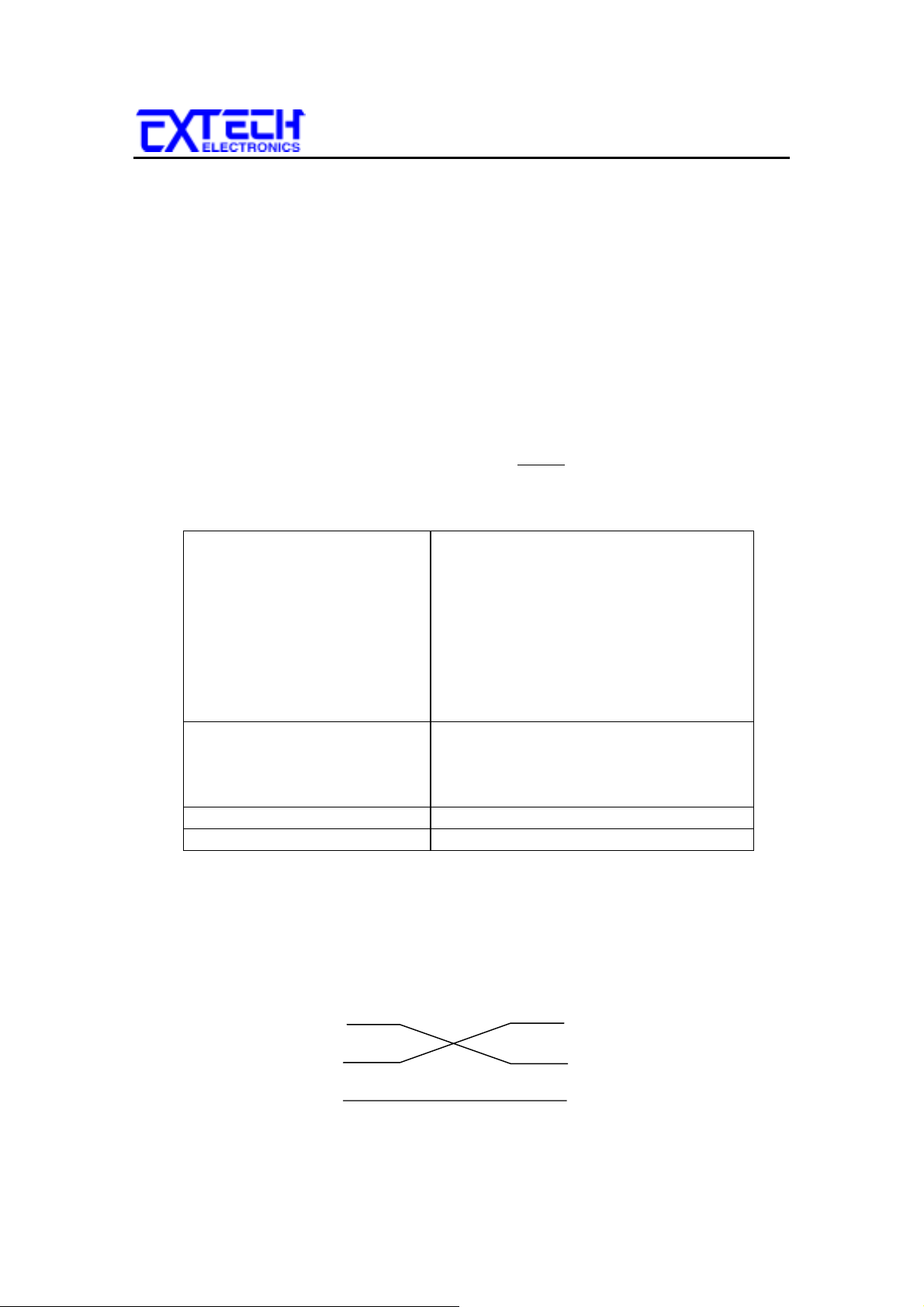
RS232 & GPIB INTERFACE
12.5 GPIB Address
Each device on the GPIB (IEEE-488) interface must have a unique address. You
can set the address of the 7611 to any value between 0 and 30. The address is set
to 5 when the instrument is shipped from the factory. The address can only be set
from the front panel. The address is stored in non-volatile memory and does not
change when the power has been off or after a remote interface reset.
12.6 Interface Functions
The capability of a device connected to the bus is specified by its interface
functions. These functions provide the means for a device to receive, process, and
send messages over the bus. The interface functions are listed in the chart below.
All functions may be controlled over the bus except
Selectable on the rear panel.
GPIB INTERFACE FUNCTIONS
IEEE-488 INTERFACE
CONTROLLABLE ITEMS
DATA CODES ASCII
DELIMITER CR + LF (+ EOI)
12.7 RS-232 Interface
The RS-232 cabling should be configured as follows for a 9 pin serial port
interface:
Instrument RS-232 Port PC / Bus Controller
input voltage which is
Complete handshake capability
Talker/Listener functions
Service request capability
No remote/local capability
No parallel poll capability
No device clear capability
No device trigger capability
No controller capability
3 state driver
Test/Reset control
Setting of test status/parameters for test
LCD Display Reading
Test Results Reading
RD
TD
SIG
GND
2
3
5
RD
2
3
TD
SIG
5
GND
44
Page 51
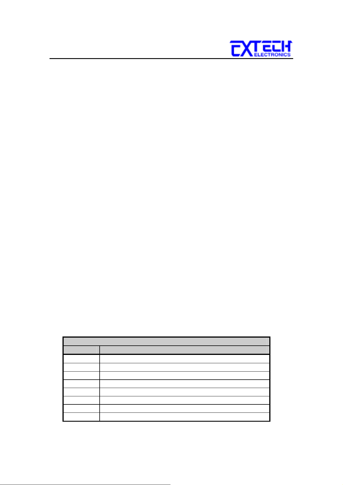
RS232 & GPIB INTERFACE
The COM port should have the following configuration. 9600 baud, 8 data bits, 1
stop bit, no parity. This interface does not support XON/XOFF protocol or any
hardware handshaking. The controller should be configured to ignore the
handshaking lines DTR (pin 4), DSR (pin 6) CTS (pin 8) and RTS (pin 7). If the
port can not be configured through software to ignore the lines then the handshake
lines should be jumpered together in two different sets. Pins 4 and 6 jumpered
together and pins 7 and 8 jumpered together at the controller end of the cable.
When sending command over the RS232 bus the instrument will echo a response
string identical to the string that was sent if the transfer was recognized and
accepted by the instrument. This allows for software handshaking, to monitor and
control data flow. If there is an error with the command string that is sent, the
instrument will respond with 15h or the “NAK” ASCII control code. When
requesting data from the instrument, it automatically send the data to the
controller input buffer. The controller input buffer will accumulate data being sent
from the instrument including the echo response string, until it is read by the
controller.
12.8 7611 GPIB Interface Command List
When the GPIB controller sends a correct command beginning with an “S” or “F”
the instrument will echo back the identical command string. A GPIB read
command must be sent after the command string to view this echo response.
If an error occurs when a command is sent, or the instrument does not recognize
the command then the instrument will respond with a value of ASCII “NAK”
(15hex), after the read command is sent. Each string should be terminated by
ASCII <LF> and <CR>. ALL commands are case sensitive.
12.8.1
Parameter Selection Commands
The following commands are used to toggle ON/OFF functions or menu selection
items. No other values or additional parameters are needed to execute these
commands.
System Settings and Commands
Command Function
FA Test
FB Reset
FQ Connect On
FR Connect Off
FS Fail Stop On
FT Fail Stop Off
FY Single Step On
FZ Single Step Off
45
Page 52
RS232 & GPIB INTERFACE
Line Configuration Settings
Command Configuration
NEUTRAL REVERSE GROUND
SL1 Fault Normal Fault
SL2 Fault Fault Fault
SL3 Fault Normal Normal
SL4 Fault Fault Normal
SL5 Normal Normal Fault
SL6 Normal Fault Fault
SL7 Normal Normal Normal
SL8 Normal Fault Normal
Probe Configuration Settings
Command Configuration
SP1 Measurement from ground to line
SP2 Measurement from Probe-HI to line
SP3 Measurement from Probe-HI to Probe-LO
Measuring Device Settings
Command Configuration
SDA Set measuring device circuit A for UL544 non patient care
SDB Set measuring device circuit B for UL544 patient care
SDC Set measuring device circuit C for UL2601, IEC601
SDD Set measuring device circuit D for UL1563
SDE Set measuring device circuit E for UL3101,UL1950
SDF Set measuring device circuit F for external
12.8.2
Parameter Data Input Commands
The
following commands require a numeric value to follow the command string.
Parameter Setting
Command Function Value Unit
S5 Memory Select 1 - 50 Integer
S6 Step Select (1-8) 1 - 8 Integer
SC Setting of Current
1 - 6000
A
µ
High Trip Value
SB Setting of Current
1 - 6000
A
µ
Low Trip Value
ST Setting of Delay
0.0 - 999.9 Seconds
Time
12.9.3
Data Retrieval Commands
The following commands are used to retrieve information from the Line Leakage
46
Page 53
RS232 & GPIB INTERFACE
Tester. After the command is sent a GPIB read command must follow to retrieve
the data from the instrument in GPIB operation. In RS-232 operation the Line
Leakage Tester will automatically send the results to the data buffer at the
controller.
Query Commands
Command Description Bytes Returned
?n
n=1-16
?K LCD READ used for active polling if the
Returns the results of the test that was
executed on the nth step from the start of the
test sequence.
40 bytes
40 bytes
active LCD display during or after the test.
?D Read the status of the Reset input 1 byte
0 = OFF
1 = ON
The “n” within the read buffer command ?n represents the number of the test in a
sequence of tests and not the actual step number. The test number starts with 1 as
the first test performed. For example, if three steps were executed as a sequence,
using steps 5, 6 and 7, the results from step 5 will be retrieved from the 1st buffer
using the ?1 command not ?5.
12.8.4 GPIB Service Request
SRQ Configuration Settings
F0 Enable “All Pass” SRQ
F1 Disable “All Pass” SRQ
F2 Enable “Fail” SRQ
F3 Disable “Fail” SRQ
F4 Enable “Abort” SRQ
F5 Disable “Abort” SRQ
F6 Enable “Error Command” SRQ
F7 Disable “Error Command” SRQ
The service request capability is not available with the RS-232 interface. The
service request status byte can be read from the instrument only after one or more
of the service request functions have been enabled. The status byte bit
assignments are as follows.
BIT 7 6 5 4 3 2 1 0
Function na RQS na na ERROR ABORT FAIL PASS
The bit will be active or 1 when the SRQ function has been enabled and the
condition is true. Bit 6 is the RQS bit and will be active when the instrument has
47
Page 54

RS232 & GPIB INTERFACE
detected that an enabled SRQ has been met and therfore has requested service.
Bit 4,5, and 7 are not used and will be set to false or 0 for all status reads.
After the status byte has been read from the instrument the RQS bit will be
cleared to 0 and the remaining bits will be unchanged. The remaining bit will be
unchanged until the next time service is requested.
For example, after the All Pass SRQ has been enabled, when the test(s) have
finished with pass indications the instrument will set the hardware SRQ line and
output the status byte of 41 hex. This means that bit 6 and bit 0 are set to a value
of 1. After reading the status byte the status byte value will change to 01 hex and
remain at 01 hex until next time service is requested.
12.9 Example of Communicating Over the GPIB bus
To write commands over the GPIB bus you must enter the code that is specific to
the software language you are using. Then follow the example below:
To set the High Current Trip across the GPIB bus at 1000 µA do the following.
First select the memory and step that you wish to change Then send the string
“SC 1000”
: This tells the instrument to set the High Current Trip to 1000 µA. A
string is a list of ASCII characters, octal or hex bytes or special symbols, enclosed
in double quotes.
If you wish to set the Delay time of the test across the GPIB bus at 10 seconds, do
the following, send the string
“ST 10.00”
. This tells the instrument to set the
Delay Time at 10.00 seconds for the Memory and step that has been selected.
To read the 2 x 20 display, first send the string
“?K”
then send the GPIB
command to read 40 bytes. The instrument will send 40 bytes, one byte for each
character on the display, including spaces.
12.10 Non Volatile Memory
The instrument saves each parameter in non-volatile memory when the parameter
is changed. The non-volatile memory has a limited write cycle life, therefore there
is a special volatile memory location that is available for programmers who wish
to send all parameters before executing each test. Memory 9, step 8 is the
memory location that will
Settings written to this location from GPIB mode will be lost when power is shut
down. Parameter changes to this location is unlimited and will not effect the life
of the internal non-volatile memory chip.
write the parameter to non-volatile memory.
NOT
48
Page 55
CALIBRATION PROCEDURES
CHAPTER 13 :
OPTIONS
13.1 Introduction
This section contains a list and descriptions of available factory installed options at the
time of this printing. The list of options contains an option code number that can be
referenced on the rear panel of the unit.
13.2 Option Label
On the rear panel of the instrument you will find a label that contains the option code.
For example your options code would appear as follows:
fitted with option 01 .............................................................. OPT: 01
fitted with option 01 and 02.................................................... OPT: 0102
7611 Options
Option List
Code Description
01 RS232 Interface
02 TBD
RS232 Interface
01
This option may be substituted for the standard GPIB interface. This option
provides all of the command control of the GPIB interface with the exception of the
SRQ commands. All commands can be found in the GPIB portion of the Operation
section of this manual.
The RS232 cabling should be configured as follows for a 9 pin serial port interface:
7611 PC / Bus Controller
RD
TD
SIG
GND
2
3
5
RD
2
3
TD
SIG
5
GND
The COM port should have the following configuration. 9600 baud, 8 data bits, 1
stop bit, no parity. This interface does not support XON/XOFF protocol or any
hardware handshaking. The controller should be configured to ignore the
handshaking lines DTR (pin 4), DSR (pin 6) CTS (pin 8) and RTS (pin 7). If the
port can not be configured through software to ignore the lines then the handshake
lines should be jumpered together in two different sets. Pins 4 and 6 jumpered
together and pins 7 and 8 jumpered together at the controller end of the cable.
49
Page 56

CALIBRATION PROCEDURES
When sending command over the RS232 bus the 7611 will echo a response string
identical to the string that was sent if the transfer was recognized and accepted by
the instrument. This allows for software handshaking, to monitor and control data
flow. If there is an error with the command string that is sent, the instrument will
respond with 15h or the “NAK” ASCII control code. When requesting data from the
instrument, it automatically sends the data to the controller input buffer. The
controller input buffer will accumulate data being sent from the instrument including
the echo response string, until it is read by the controller.
50
Page 57
CALIBRATION PROCEDURES
CHAPTER 14 : CALIBRATION PROCEDURES
14.1 Calibration
Press the calibration button on the rear panel when the display shows:
Calibrate 7611
Press CAL button
A complete calibration includes:
1. Meter auto null
2. Meter gain calibration
3. Meter ratio auto check
4. DUT voltmeter calibration
5. Measuring Device calibration
Procedure 1 and 3 are internal and automatic. Procedure 2, 4, and 5 require the
following equipment:
1. AC 120V source with Standard AC Voltage meter
2. Standard Current Meter, 10mA range
3. 1KΩ 1/4W Resistor
4. DC source with 2.2V and 3.1V capability
14.2 Enter The Maintenance Mode
Press and hold the calibration key on the rear panel with a pen, pencil or small
screw driver while powering ON the 510L. The 510L enters maintenance mode
after the power on sequence is complete. The initial screen will show:
Maintenance mode
SETUP for menu
Use the SETUP key to scroll through the menu. The selections are Calibration,
EEPROM Initialization, and Restore Default MD:F.
14.2.1
Calibration Initialization
Press the SETUP key, the program will advance to the Calibration
selection mode. The display will show:
Calibrate 7611
Press CAL button
Please refer to section 2. for the actual calibration procedure.
51
Page 58
14.2.2
14.2.3
CALIBRATION PROCEDURES
EEPROM Initialization
Press the SETUP key, the program will advance to the EEPROM Initialization
selection mode. The display will show:
Initiate EEPROM
Press ENTER
The EEPROM initialization will restore all memory locations with default
calibration data. All previous calibration data will be lost. Press the ENTER key
and the display will prompt you to continue with the EEPROM initialization as
follows:
Erase Cal. (Y/N)?
Y= ENTER N= EXIT
Press the ENTER key to begin the initialization. If the EXIT key is pressed you
will return to the maintenance menu. When the initialization has started the
display will show:
Initializing...
Please wait
Restore Measuring Device F Default
Press the SETUP key, the program will advance to the MD:F default restore mode.
The display will show:
Restore MD:F
Press ENTER
Press the ENTER key to restore the device F default value to 1 KΩ. The display
will momentarily display the default value and return to the previous screen. The
display will show:
Restore MD:F
MD : F = 1000
This function is used to restore the default value before verifying the bandwidth of
the leakage current “voltmeter.” If measuring device F has never been calibrated
using a new measuring device circuit then you may not need to perform this
default restore. The default setting from the factory is 1 KΩ.
52
Page 59
CALIBRATION PROCEDURES
The calculation of the displayed leakage current will use 1000 Ω for R in the
calculation of V/R=I where I is the leakage current displayed and V is voltage across
the measuring device (MD). The probe should be selected to P
selected to F. When an external frequency generator is applied to the probe inputs then
the current display will be equal to Voltage generator/1000. The readings can then be
correlated to verify the voltmeter bandwidth. Since the voltage is being applied directly
across the MD voltmeter amplifier inputs it is not necessary to actually install a 1KΩ
resistor to the external MD:F inputs. However, to complete the circuit a jumper should
be applied between the two red terminals V and I of the external MD:F inputs.
14.2.4
Meter Auto Zero
Press the SETUP key, the program will advance to the Meter Auto Zero calibration.
The display will show:
Meter Auto Zero
TEST to start
Make sure that Probe HI and LO are shorted and that the DUT power connection have
been disconnected. There should not be any DUT input voltage during the Auto Zero
calibration.
Press TEST and wait for the 7611 to check the zero of each range. The first line shows
the range. Two numbers appear on the second line. The number on the left (NU=XX)
is the auto-null DAC setting that minimizes the RMS to DC converter output offset.
The number on the right (OS=XX) is the residual offset after the auto-null. This offset
is subtracted in software to make the reading zero when there is no input. No user
adjustable parameters are necessary. The screens will be displayed as follows as the
auto zero is executed.
Auto zero . . .
takes ∼ 90 sec.
Range 0 null . . .
NU = XX , OS = XX
Range 1 null . . .
NU = XX , OS = XX
Range 2 null . . .
NU = XX , OS = XX
Range 3 null . . .
NU = XX , OS = XX
Range 4 null . . .
NU = XX , OS = XX
53
and the MD
H-PL
Page 60
14.2.5
14.2.6
CALIBRATION PROCEDURES
DUT voltage null . . .
OS = XX , DONE.
Meter Gain Calibration
Press the SETUP key, the program will advance to the meter gain calibration. The
display will show:
ENTER meter gain
Calibration
Apply 2.2VDC between Probe HI and Probe LO, then press ENTER. 7611 displays the
voltage it measures. The display will show:
XXXX mV
Enter probe mV
Key in the correct voltage as necessary. The ENTER key enters the number into
calibration data and refreshes the voltage display. The EXIT key exits without
changing calibration and returns the menu back to the previous screen.
Meter Range Auto Calibration
Press the SETUP key, the program will advance to the Ratio Check calibration. The
display will show:
Ratio check
TEST to start
Press the Test button to start the process. In this procedure, 7611 uses the gain
calibration data from procedure 2 to calibrate other ranges. It is fully internal and
automatic. There is a dedicated DAC for the ratio check. During the ratio check, 7611
displays the raw ADC readings. The screens will be displayed as follows as the Ratio
Check is executed.
Auto gain ratio
takes ∼ 25 sec.
RAN1: XXXX
RAN0: XXXX
RAN1: XXXX
RAN2: XXXX
RAN2: XXXX
RAN3: XXXX
54
Page 61
CALIBRATION PROCEDURES
RAN3: XXX
RAN4: XXXX
14.2.7
DUT Voltmeter Calibration
Press the SETUP key, the program will advance to the AC voltage
calibration. The display will show:
ENTER AC Voltage
calibration
This is similar to the gain calibration where a known voltage source is applied to the
DUT power input. Apply 60Hz, 120 V rms to the DUT power input. Then press the
ENTER key. The 7611 shows the measured voltage.
XXX.X V
Enter Line Volt
Key in the correct voltage then press the ENTER key. The voltage reading will be
updated. When the calibrated value is correct press the EXIT key to return to the
previous screen.
14.2.8
Measuring Device Calibration
Press the SETUP key, the program will advance to the MD circuit calibration. The
display will show:
ENTER MD:A
calibration
The last five calibration items are to calibrate the MD resistor values. Connect a DC
voltage source in series with 1K resistor, a current meter and the probe input terminal
(Probe HI to Probe LO). The voltmeter should be set to 3.1V DC. Press the ENTER
key. There will be a short pause while the MD circuit is configured and a current
reading is taken, and then the display will show:
MD:A, I= XXXX µA
Enter probe µA
Enter the reading of current meter and press the ENTER key. The data will be saved
and returns to the same screen with the new current reading. The value can then be reentered if necessary, or press the EXIT key when the calibration is acceptable.
Press the SETUP key again and the MD will advance to MD:B. The display will show:
ENTER MD:B
calibration
55
Page 62

Press the Enter Key the display will show:
MD:B, I= XXXX µA
Enter probe µA
This process continues and is the same for all Measuring Devices A through F.
14.3 Finished
Once all the calibration procedures are complete, then press the EXIT key to return to
the Calibration Main Menu. Press the EXIT key a second time to return to normal
operation mode. The Set screen will show the settings of the test that is ready to be
executed. The instrument is now ready to perform any calibration verification or
testing procedures.
CALIBRATION PROCEDURES
56
 Loading...