

Page 1
USER MANUAL
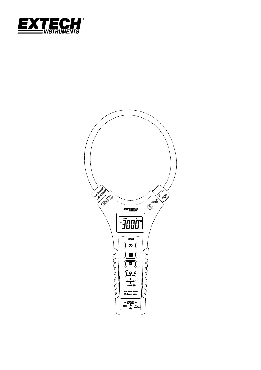
3000A TRUE RMS AC Flexible Clamp Meter
Model MA3110
Additional User Manual Translations available at www.extech.com
Page 2

MA3110-en-GB_V1.0 12/16
2
Introduction
Thank you for choosing the Extech Model MA3110 Flexible AC Clamp meter with automatic
ranging, data hold, and auto power OFF. The MA3110 is a professional CAT III 1000V instrument
that measures up to 3000A AC RMS. The MA3110 also measures DC and AC Voltage, Resistance,
Capacitance, Diode, and Continuity (beeper). This device is shipped fully tested and calibrated
and, with proper use, will provide years of reliable service. Please visit our website
(www.extech.com) to check for the latest version of this User Guide, Product Updates, Product
Registration, and Customer Support.
Features
600A and 3000A AC True RMS Current Measurement ranges
AC (True RMS) and DC Voltage Measurements
Automatic ranging
Meets IEC61010-1, 3
rd
Edition (2010) CAT III 1000V Safety requirements.
Resistance, Capacitance, Diode, and Continuity Beeper
Data Hold feature freezes displayed reading
6000 count large scale LCD display
Convenient Flexible Clamp with locking mechanism
8mm (0.3”) coil diameter for measuring in tight spaces
Coil length 300mm (11.8“)
Auto Power OFF after 15 minutes of inactivity
Overload Protection for most ranges
Durable, long-lasting components, enclosed in strong, lightweight ABS-plastic housing.
Page 3

MA3110-en-GB_V1.0 12/16
3
Safety Information
To ensure the safe operation and service of the meter, follow these instructions closely. Failure to
observe warnings can result in severe injury.
Precautions and Preparations for Measurements
Ensure that the batteries are connected in the correct polarity and placed in the battery
compartment (rear) correctly.
Place the red and black test leads into the proper input terminals before making
measurements.
Remove the test leads from the circuit under test when changing the measurement ranges.
Do not exceed the maximum rated voltage and current on the meter input terminals.
Remove the battery if the meter is to be stored for long periods
Replace the test leads only with ones rated for CAT III 1000V or better.
The meter has an automatic power OFF (APO) utility that switches the meter OFF after 15
minutes of inactivity. Press any key to wake the meter. To disable this feature, press and
hold the M (mode) button while switching the meter ON.
Warnings
Warnings identify hazardous conditions and actions that could cause BODILY HARM or DEATH.
Individual protective equipment should be used if HAZARDOUS LIVE parts in the installation
where measurements are to be carried out could be accessible.
If the equipment is used in a manner not specified by the manufacturer, the protection
provided by the equipment may be impaired.
To reduce the risk of fire or electric shock, do not expose this product to rain or moisture.
Verify the meter operation by measuring a known current. If in doubt, have the meter
serviced.
Do not apply more than the rated voltage/current as marked on the meter.
To avoid false readings that can lead to electric shock and injury, replace battery as soon as
the low battery indicator appears.
Do not use the meter in or around explosive gas or vapor.
Do not use a flexible current sensor if the inner copper wire of the flexible cord is visible.
De-energize the installation under test or wear suitable protective clothing when placing or
removing the flexible current probe from a test setup.
Do not apply/remove the flexible current probe to/from UNINSULATED HAZARDOUS LIVE
conductors that may cause electric shock, electric burn, or arc flash.
Page 4
MA3110-en-GB_V1.0 12/16
4
CAUTIONS
CAUTIONS identify conditions and actions that could cause DAMAGE to the meter or equipment
under test. Do not expose the meter to extremes in temperature or high humidity.
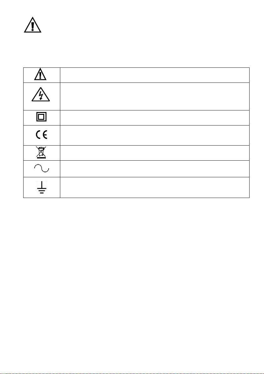
Safety Symbols that are typically marked on meters and instructions
Caution: Do not apply voltage or current to the input terminals or clamp that
exceeds the specified ranges
Caution: Risk of electric shock!
Equipment protected by double or reinforced insulation
Conforms to EU directives
Do not discard this product in household trash.
AC measurement
Earth ground
PER IEC1010 OVERVOLTAGE INSTALLATION CATEGORY
OVERVOLTAGE CATEGORY I
Equipment of OVERVOLTAGE CATEGORY I is equipment for connection to circuits in which
measures are taken to limit the transient over-voltages to an appropriate low level.
Note – Examples include protected electronic circuits.
OVERVOLTAGE CATEGORY II
Equipment of OVERVOLTAGE CATEGORY II is energy-consuming equipment to be supplied from
the fixed installation.
Note – Examples include household, office, and laboratory appliances.
OVERVOLTAGE CATEGORY III
Equipment of OVERVOLTAGE CATEGORY III is equipment in fixed installations.
Note – Examples include switches in the fixed installation and some equipment for industrial use
with permanent connection to the fixed installation.
OVERVOLTAGE CATEGORY IV
Equipment of OVERVOLTAGE CATEGORY IV is for use at the origin of the installation.
Note – Examples include electricity meters and primary over-current protection equipment.
Page 5
MA3110-en-GB_V1.0 12/16
5
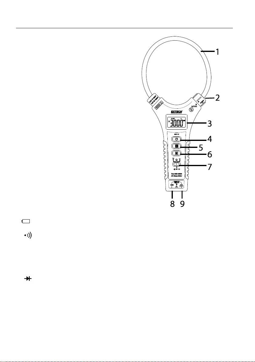
Description
Meter Description
1. Flexible Current Clamp
2. Clamp Lock Mechanism
3. 6000-count LCD Display
4. Power button
5. Data Hold Button
6. MODE (M) Button
7. Function Switch
8. COM (-) test lead input terminal
9. Positive (+) test lead terminal
Display Icons
H Data Hold
AUTO Automatic Range mode
AC Alternating Current
DC Direct Current
Low battery icon (flashing when measurements cannot be expected to be in-
specification)
Continuity alert (beeper)
V Unit for Voltage measurements
A Unit for Current measurements
Ω, KΩ, MΩ Units for Resistance measurements
nF, uF Units for Capacitance measurements
Diode measurements
OL ‘Overload’ for over range measurements (voltage, current and resistance)
- Minus symbol (negative) when the measurement value is negative
Page 6

MA3110-en-GB_V1.0 12/16
6
Operation
NOTES: Read and understand all Warning and Caution statements in this operation manual
prior to using this meter.
Meter Power
The meter is powered by two (2) 1.5V ‘AAA’ batteries. The battery compartment is located on the
back of the meter. Press the Power button to switch the device ON or OFF.
Low battery indication
When the low battery icon appears ( ) the batteries should be replaced immediately,
although in-specification measurements can still be made temporarily. When the low battery
icon begins blinking, in-specification measurements are no longer supported and batteries must
be replaced before further measurements can be made. Refer to the battery replacement
procedure in the maintenance section.
Automatic Power OFF
The meter switches OFF automatically after a 15-minute period of inactivity. To disable the Auto
Power OFF feature:
With the meter power OFF, press and hold the Mode (M) button while powering the
meter ON.
The APO feature is now disabled and the meter will not shut off automatically.
Note that the next time the meter is powered up, the Auto Power OFF function will be
enabled again and the user will have to repeat the Auto Power OFF disable instructions
to disable this function when desired.
Data Hold
Press the H (HOLD) button with the meter ON to freeze the displayed reading. The H icon will
appear along with the held reading. Press the H (HOLD) button again to release the HOLD feature.
The H icon will switch OFF and the meter will show real time readings.
Page 7

MA3110-en-GB_V1.0 12/16
7
DC and AC Voltage Measurements
WARNING: Use the test lead probe covers for CAT IV 600V installations. Do not measure
voltages greater than 1000V.
CAUTION: When connecting the test leads to the circuit or device under test, connect the
black lead before the red; when removing the test leads, remove the red before the black lead.
1. Connect the black test lead into the COM terminal.
2. Connect the red test lead into the ‘V’ terminal.
3. Power the meter using the power button .
4. Put the function switch to the ‘V’ position.
5. The display will show the ‘AUTO’ icon (Auto Range mode).
6. Press the M (MODE) button to select AC or DC voltage.
7. Press the test leads across the circuit under test and read the voltage on the display.
8. In the Auto Range mode, the meter will automatically select the optimal range. AC voltage
measurements are True RMS readings.
Page 8

MA3110-en-GB_V1.0 12/16
8
AC Current Measurements
WARNING: Ensure that power to the device under test is OFF before starting this
procedure. Switch power to the device under test ON only after the clamp has been safely
attached to the device under test.
CAUTION: Do not move fingers above the LCD at any time during a test.
1. Switch the meter OFF and switch OFF power to the device under test.
2. Switch the meter ON and select ‘A’ with the function switch. The display will show the
automatic range icon (AUTO).
3. Turn the knurled clamp lock mechanism counter-
clockwise to release the flexible clamp.
4. Fully enclose only one conductor of the device under
test with the flexible clamp probe (see accompanying
diagrams). Do not attempt to measure current higher
than the specified current limit.
5. Re-lock the clamp turning the clamp lock clockwise.
6. Switch power to the device under test ON. Never move fingers above the LCD when
running a test.
7. Read the current value in the display. The meter will automatically select the appropriate
range (600.0A and 3000A).
Page 9

MA3110-en-GB_V1.0 12/16
9
Resistance Measurements
CAUTION: Disconnect power to the circuit or device under test when making resistance
measurements
1. Connect the black test lead into the COM terminal.
2. Connect the red test lead into the ‘Ω’ terminal.
3. Power the meter using the power button .
4. Put the function switch to the ‘Ω’ position.
5. The display will show the ‘AUTO’ icon (Auto Range mode).
6. Press the M (Mode) button to select resistance Ω mode.
7. Press the test leads across the circuit under test and read the resistance on the display.
8. In the Auto Range mode, the meter will automatically select the optimal range.
Page 10

MA3110-en-GB_V1.0 12/16
10
Continuity Measurements
CAUTION: Disconnect power to the circuit or device under test when making continuity
measurements
1. Connect the black test lead into the COM terminal.
2. Connect the red test lead into the ‘ohms’ terminal.
3. Power the meter using the power button .
4. Put the function switch to the ‘ohms’ position.
5. The display will show the ‘AUTO’ icon (Auto Range mode).
6. Press the M (Mode) button to select continuity mode.
7. The display will show “MANU” icon (Manual Range mode).
8. Press the test leads across the circuit under test. The meter will beep and the display will
show the continuity symbol when the resistance is < 20 ohms.
Page 11

MA3110-en-GB_V1.0 12/16
11
Diode Measurements
CAUTION: Disconnect power to the circuit or device under test when making diode
measurements
1. Connect the black test lead into the COM terminal.
2. Connect the red test lead into the ‘Ω’ terminal.
3. Power the meter using the power button .
4. Put the function switch to the ‘Ω’ position.
5. The display will show the ‘AUTO’ icon (Auto Range mode).
6. Press the M (Mode) button to select diode mode. The display will show the manual
mode symbol (MANU).
7. When connected as shown in test position 1 a forward current flow is established and
the approximate diode forward voltage (VF) value is displayed. If the diode under test is
defective ‘0.000’ (short circuit) or ‘OL’ (open circuit) will display.
8. When connected as shown in test position 2 a reverse polarity check is made. If the diode
under test is good, ‘OL’ will be displayed. If the diode is defective ‘0.000’ or other values
will be displayed. Proper diode testing should include both polarity measurements.
Page 12

MA3110-en-GB_V1.0 12/16
12
Capacitance Measurements
CAUTION: Discharge the capacitor under test before taking any capacitance
measurements
1. Connect the black test lead into the COM terminal.
2. Connect the red test lead into the ‘Ω’ terminal.
3. Power the meter using the power button .
4. Put the function switch to the ‘Ω’ position.
5. The display will show the ‘AUTO’ icon (Auto Range mode).
6. Press the M (Mode) button to select the capacitance mode.
7. Press the test leads across the circuit under test and read the capacitance on the display.
8. In the Auto Range mode, the meter will automatically select the optimal range.
Page 13

MA3110-en-GB_V1.0 12/16
13
Maintenance
WARNING: To avoid electrical shock, disconnect the meter from any circuit and turn OFF the
meter before opening the case. Do not operate the meter with an open case.
Cleaning and Storage
Periodically wipe the case with a damp cloth and mild detergent; do not use abrasives or
solvents. If the meter is not to be used for 60 days or more, remove the batteries and store them
separately.
Battery Replacement
CAUTION: Remove the meter from the conductor under test and switch the meter OFF
before opening the battery compartment.
1. Remove the screw that secures the rear battery compartment.
2. Remove the battery compartment cover.
3. Replace the 2 ‘AAA’ 1.5V batteries observing correct polarity.
4. Re-attach the battery compartment cover.
5. Secure the battery compartment with the screw.
Never dispose of used batteries or rechargeable batteries in household waste.
As consumers, users are legally required to take used batteries to appropriate
collection sites, the retail store where the batteries were purchased, or wherever
batteries are sold.
Disposal: Do not dispose of this instrument in household waste. The user is obligated
to take end-of-life devices to a designated collection point for the disposal of electrical
and electronic equipment.
Specifications
Function
Range
Resolution
Accuracy
DC Voltage
6V
0.001V
±(0.8% + 5 digits)
60V
0.01V
600V
0.1V
1000V
1V
Input impedance: 10MΩ; Overload protection: ± 1000V DC and AC
AC Voltage
6V
0.001V
± (1.0% + 8 digits)
(50/60Hz)
True rms
60V
0.01V
600V
0.1V
1000V
1V
Input impedance: 10M ohms; Overload protection: ± 1000V DC and AC
Page 14

MA3110-en-GB_V1.0 12/16
14
AC Current
600.0A
0.1 A
±(1.0% + 8 digits)
3000 A
1 A
±(1.0% + 10 digits)
True rms AC measurements
Linearity: ± 0.2% of reading from 10% to 100% of range
Conductor position sensitivity: ± (2.0% +15dgts) with the measured conductor a distance from
the center > 25mm (1”)
External field influence: An increase of ± 1.5% of range max. The recommended distance for
conductors from the clamp probe sides is > 200mm. Accuracy is specified for measurements
made with the conductor at the center of the clamp field.
Frequency bandwidth for AC Current Measurements: 50/60Hz
Resistance
600 Ω
0.1 Ω*
±(1.0% + 5 digits)
6K Ω
0.001K Ω*
±(1.5% + 5 digits)
60K Ω
0.01K Ω*
600K Ω
0.1K Ω*
6M Ω
0.001M Ω*
60M Ω
0.01M Ω*
±(3.0% + 5 digits)
Overload protection: ± 350 V DC & AC
*This is the resolution when measuring a fixed resistance < 90% of the range. The resolution
decreases by a factor of 10 when the measured resistance is > 90% of the range.
Capacitance
6nF
0.001 nF
±(3.0% + 10 digits)
60nF
0.01 nF
600nF
0.1 nF
6uF
0.001 uF
60uF
0.01 uF
600uF
0.1 uF
Overload Protection: ± 30 V DC & AC (Always discharge capacitors before testing)
Continuity
Visual and audible beeper alert when resistance is < 20 Ω
Diode
Short/Open, Good/Defective tests
Specifications tested under environmental conditions of RF field strength < 3V/M and frequency < 30MHz
Page 15

MA3110-en-GB_V1.0 12/16
15
GENERAL SPECIFICATIONS
Clamp Flexible type with locking mechanism
8mm (0.3”) coil diameter
300mm (11.8”) flexible cable length
Display 6000 count LCD with multi-function indicators
33.5 x 18.7mm (1.3 x 0.7”) display size
Auto range 600.0A and 3000A AC
Sampling rate 0.5 to 1 second
Low Battery indication Low voltage display alerts
Over-range indication ‘OL’ display
AC bandwidth 50/60Hz (sine wave)
AC response True RMS
Operating Temperature and Humidity
0~50C (32~122F); 80%RH maximum
Battery Two “AAA” 1.5V batteries
Battery consumption 21.1mA approximately
Auto power OFF After approx. 15 minutes of inactivity
Dimensions (W x H x D) 290 x 135 x 27.8 mm (11.4 x 5.3 x 1.09”)
Weight 208g (0.46 lbs.) without battery
Safety Standards IEC61010-1, 3rd Edition (2010); Pollution degree 2; Altitude 2000m
(6562’) maximum; Indoor use only
Voltage/Category Rating 1000V CAT III, 600V CAT IV
Current Rating 3000A
Probes Listed IEC61010-031 Probes Only
Copyright © 2016 FLIR Systems, Inc.
All rights reserved including the right of reproduction in whole or in part in any form
ISO-9001 Certified
www.extech.com
 Loading...