

Page 1
User’s Guide
Model MA150
200A AC Mini Clamp-on Meter
Page 2
Introduction
Congratulations on your purchase of Extech’s MA150 AC Mini Clamp Meter. This meter is shipped
fully tested and calibrated and, with proper use, will provide years of reliable service.
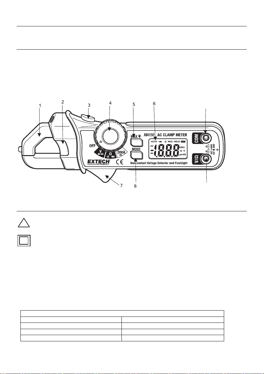
Meter Description
1. Current sense jaw
2. Non-contact AC voltage indicator light
3. Flashlight button
4. Rotary function switch
5. MAX hold and Backlight key
6. LCD display
7. Clamp trigger
8. MODE key
9. COM input jack
10. V Ω input jack
9
10
Safety Information
!
Caution! Refer to the explanation in this Manual
Double Insulation
This meter has been designed to be safe in use, but the operator must use caution in its operation.
The rules listed below should be carefully followed for safe operation.
1. NEVER apply voltage or current to the meter that exceeds the specified maximum:
2. USE EXTREME CAUTION when working with voltages greater than 60VDC or 25VAC rms.
These voltages are considerd a shock hazard.
3. NEVER operate the meter unless the back cover and the battery/fuse door are in place and
fastened securely.
Function Maximum Input
AC Current 200A
AC/DC Voltage 600V AC/DC
Resistance, Diode, Continuity Test 600V AC/DC
Input Limits
2
MA150-EN-V2.1-3/12
Page 3
Operation
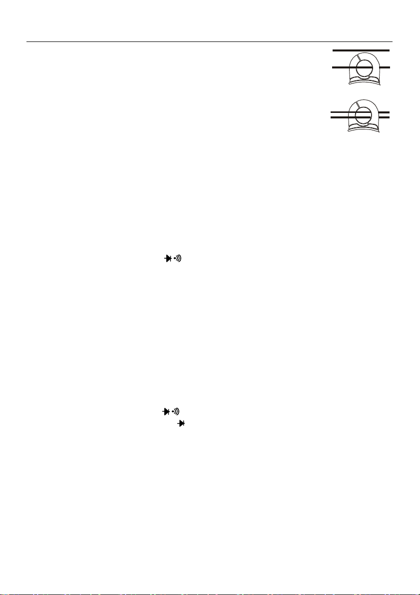
AC Current Measurements
1) Set the Function switch to the 200A AC range.
2) Press the jaw trigger and clamp around, fully enclosing a single conductor.
Do not allow a gap between the two halves of the jaw. Refer to the diagram
at right for the correct way to enclose a single conductor.
3) Read the ACA value on the LCD.
AC/DC Voltage Measurements
1) Insert the black test lead into the negative COM terminal and the red test lead into the positive V
terminal.
2) Set the function switch to the V position.
3) Select AC or DC with the MODE button.
4) Connect the test leads in parallel to the circuit under test.
5) Read the voltage measurement on the LCD display.
Resistance and Continuity Measurements
1) Insert the black test lead into the negative COM terminal and the red test lead into the positive V
Ω terminal.
2) Set the function switch to the Ω position.
3) Use the MODE button to select resistance. The MΩ icon will appear in the display.
4) Touch the test leads across the circuit or component under test. It is best to disconnect one side
of the device under test so the rest of the circuit will not interfere with the resistance reading.
5) For Resistance tests, read the resistance on the LCD display
6) For Continuity, use the MODE button to select continuity “•)))”. The display icons will change
when the MODE button is pressed.
7) If the resistance is <120 Ω a tone will sound.
Diode Test
1) Insert the black test lead banana plug into the negative COM jack and the red test lead banana
plug into the positive V Ω jack.
2) Set the function switch to the Ω position.
3) Press the MODE button to indicate on the display.
4) Touch the test probes to the diode under test. Forward voltage will typically indicate 0.400 to
0.700V. Reverse voltage will indicate “OL”. Shorted devices will indicate near 0V and an open
device will indicate “OL” in both polarities.
Yes
No
3
MA150-EN-V2.1-3/12
Page 4

Non-Contact AC Voltage Detection
WARNING: Risk of Electrocution. Before use, always test the Voltage Detector on a
known live circuit to verify proper operation
1) AC Voltage detection operates on any of the three Function switch positions.
2) Touch the probe tip to the hot conductor or insert into the hot side of the electrical outlet.
3) If AC voltage is present, the detector light will illuminate.
NOTE: The conductors in electrical cord sets are often twisted. For best results, slowly slide the
probe tip along a length of the cord to assure placing the tip in close proximity to the live
conductor.
NOTE: The detector is designed with high sensitivity. Static electricity or other sources of energy
may randomly turn the detector light on. This is normal operation
MAX Hold
To hold the highest reading on the LCD, momentarily press the “MAX
” key. The meter reading will
not change as readings change, rather it will only display the highest reading encountered since the
MAX hold button was pressed. Press the MAX hold button again to return the meter to normal
operation.
Backlight
Press and hold the “MAX
” key for more than one second to turn the backlight on. This will also
activate the MAX Hold function. To release the MAX Hold function and return the meter to normal
operation, press the “MAX
seconds. To manually turn off the backlight, press and hold the “MAX
” key momentarily. The backlight will automatically turn off after 15
” key for more than 1 second.
Flashlight
Press and hold the top button to turn the flashlight on. Release the button to turn the flashlight off.
4
MA150-EN-V2.1-3/12
Page 5

Specifications
General Specifications
Display 2000 count Digit LCD with white LED backlight
Polarity Minus sign (-) indicates negative polarity
Jaw opening 0.7” (18mm)
Current sensor Hall effect sensor type
AC Current Bandwidth 50/60Hz
AC Voltage Bandwidth 50/400Hz
Overload indication “OL” displayed on the LCD
Display rate 2 readings/second, nominal
Battery Two 1.5V AAA batteries
Low Battery indication “BATT” displayed on the LCD
Auto Power off approx. 15 minutes
Operating conditions 32 to 86
Storage conditions - 14 to 140
Altitude Operate at less than 3000 meters
Weight 6.2 oz. (176g) including battery
Dimensions 6.5 x 2.6 x 1.3” (164 x 65 x 32mm) (HWD)
Standards For indoor use and in accordance with the requirements for double
º
F (0 to 30ºC) 90%RH; 86 to 104ºF (30 to 40ºC) 75%RH; 104 to
º
F (40 to 50ºC) 45%RH
122
insulation to IEC1010-1 (1995): EN61010-1 (1995) Overvoltage Category
III 300V and Category II 600V, Pollution Degree 2.
º
F (-30 to 60ºC); < 90% Relative Humidity
C
C
5
MA150-EN-V2.1-3/12
Page 6

Range Specifications
Function Range Resolution Accuracy (of reading)
AC Current 200.0A 0.1A
DC Voltage
200.0mV 0.1mV
± (2.5% rdg + 10 digits)
±(0.5% rdg + 5 digits)
2.000V 1mV
20.00V 10mV
±(1.2% rdg + 3 digits)
200.0V 0.1V
±(1.5% rdg + 3 digits)
±(1.5% rdg + 3 digits)
AC Voltage
600V 1V
2.000V 1mV
20.00V 10mV
200.0V 0.1V
600V 1V
Resistance 200.0Ω 0.1Ω
2.000kΩ 1Ω
20.00kΩ 10Ω
200.0kΩ
100Ω
2.000MΩ 1kΩ
20.00MΩ 10kΩ
±(2.0% rdg + 4 digits)
±(1.0% rdg + 4 digits)
±(1.5% rdg + 2 digits)
±(2.0% rdg + 3 digits)
±(3.0% rdg + 5 digits)
Non-Contact AC Voltage 100VAC to 600VAC 50/60Hz
Diode Test
Test current: 0.3mA typical;
Open circuit voltage: 1.5VDC typical
Continuity Threshold <120Ω Test current <1mA
6
MA150-EN-V2.1-3/12
Page 7

Maintenance
Battery Replacement
1) When the low battery symbol appears on the LCD the batteries must be replaced.
2) Power down and remove the rear battery compartment Phillips screw.
3) Lift off the battery compartment cover and replace the two 1.5V AAA cells.
4) Replace compartment cover and secure the screw.
You, as the end user, are legally bound (EU Battery ordinance) to return all used
batteries, disposal in the household garbage is prohibited! You can hand over your
used batteries / accumulators at collection points in your community or wherever batteries /
accumulators are sold!
Disposal: Follow the valid legal stipulations in respect of the disposal of the device at the
end of its lifecycle
Cleaning
Caution: Use only a dry cloth to clean the plastic case.
Warranty
EXTECH INSTRUMENTS CORPORATION (a FLIR company) warrants this instrument to be free of defects in parts and workmanship for
one year from date of shipment (a six month limited warranty applies to sensors and cables). If it should become necessary to return the
instrument for service during or beyond the warranty period, contact the Customer Service Department for authorization. Visit our website
www.extech.com
sender is responsible for shipping charges, freight, insurance and proper packaging to prevent damage in transit. This warranty does not
apply to defects resulting from action of the user such as misuse, improper wiring, operation outside of specification, improper maintenance
or repair, or unauthorized modification. Extech specifically disclaims any implied warranties or merchantability or fitness for a specific
purpose and will not be liable for any direct, indirect, incidental or consequential damages. Extech's total liability is limited to repair or
replacement of the product. The warranty set forth above is inclusive and no other warranty, whether written or oral, is expressed or
implied.
Calibration and Repair Services
Extech offers repair and calibration services for the products we sell. Extech also provides NIST certification for most products. Call the
Customer Service Department for information on calibration services available for this product. Extech recommends that annual calibrations
be performed to verify meter performance and accuracy.
for contact information. A Return Authorization (RA) number must be issued before any product is returned to Extech. The
Support lines: U.S. 877-439-8324, Intl. 603-324-7800
Technical support: Option 3; E-mail: support@extech.com
Repair & Returns: Option 4; E-mail: repair@extech.com
Product specifications subject to change without notice
Visit our website: www.extech.com
Extech Instruments Corporation, 9 Townsend West, Nashua, NH 03063
ISO 9001 Certified since 1995
7
MA150-EN-V2.1-3/12
 Loading...