

Page 1
User Manual
InfraRed Thermometer
with Laser Pointer
MODEL IR400
Page 2
Introduction
Congratulations on your purchase of the Model IR400 IR Thermometer. The IR400 is
capable of non-contact (infrared) temperature measurements at the touch of a button. The
built-in laser pointer increases target accuracy while the backlit LCD and handy pushbuttons combine for convenient, ergonomic operation. This meter is shipped fully tested
and calibrated and, with proper use, will provide years of reliable service.
Warranty
EXTECH INSTRUMENTS CORPORATION warrants this instrument to be free of defects in parts and
workmanship one year from date of shipment (a six month limited warranty applies on sensors and cables). If it
should become necessary to return the instrument for service during or beyond the warranty period, contact
the Customer Service Department at (781) 890-7440 ext. 210 for authorization or visit our website at
www.extech.com (click on ‘Contact Extech’ and go to ‘Service Department’ to request an RA number). A
Return Authorization (RA) number must be issued before any product is returned to Extech. The sender is
responsible for shipping charges, freight, insurance and proper packaging to prevent damage in transit. This
warranty does not apply to defects resulting from action of the user such as misuse, improper wiring, operation
outside of specification, improper maintenance or repair, or unauthorized modification. Extech specifically
disclaims any implied warranties or merchantability or fitness for a specific purpose and will not be liable for
any direct, indirect, incidental or consequential damages. Extech's total liability is limited to repair or
replacement of the product. The warranty set forth above is inclusive and no other warranty, whether written or
oral, is expressed or implied.
Calibration and Repair Services
Extech offers repair and calibration services for the products we sell. Extech also
provides NIST certification for most products. Call the Customer Service Department for
information on calibration services available for this product. Extech recommends that
annual calibrations be performed to verify meter performance and accuracy.
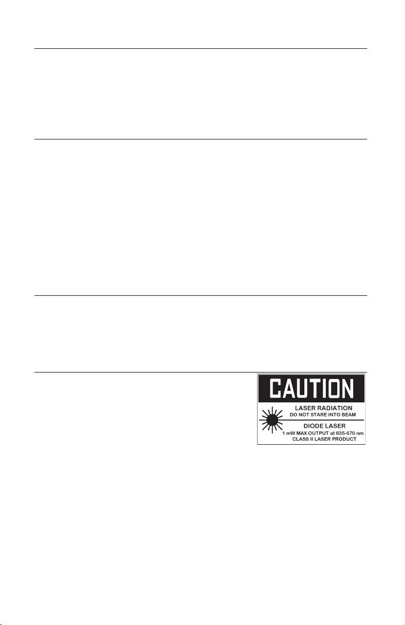
Safety
• Use extreme caution when the laser pointer beam is
on
• Do not point the beam toward anyone's eye or allow
the beam to strike the eye from a reflective surface
• Do not use the laser near explosive gases or in other
potentially explosive areas
2
IR400 V1.0 3/10
Page 3

Meter Description
Meter Description
1. Laser pointer beam
2. IR Sensor
3. Measurement Trigger
4. Battery Compartment
5. LCD Display
6. Push-buttons
7. Handle Grip
Display Description
1. Temperature scan in progress (trigger held)
2. Last reading held (trigger released)
3. Laser pointer ON
4. Emissivity (0.95 fixed)
5. Max or MIN value displayed
6. Temperature display
7. Low battery icon (replace battery)
8. Temperature units
1
2
3
5
6
4
7
3
IR400 V1.0 3/10
Page 4

Operating Instructions
Basic IR Measurements
1. Hold the meter by its handle and point it toward the surface to be measured.
2. Pull and hold the trigger to turn the meter on and begin testing. The temperature
reading, the flashing ‘SCAN’ icon, the unit of measure, and € = 0.95 will appear.
3. Release the Trigger and the reading will hold for approximately 10 seconds (HOLD will
appear on the LCD) after which the meter will automatically shut off..
Laser Pointer
1. When the trigger is pressed, the laser pointer will turn on and identify the spot being
measured. The icon on the display indicates that the pointer is on.
2. To turn the laser pointer off, press the button while scanning. Press the button
again to turn the pointer back on.
MAX - MIN
The Max / Min feature provides a means to display the highest (MAX) or lowest (MIN)
temperature measured during a scan.
1. While the trigger is pressed, press the MAX/MIN button. The “MAX” icon will appear
and the maximum measured temperature will appear in the display. The displayed
temperature will not change until a higher temperature is measured.
2. Press the MAX/MIN button again and the “MIN” icon will appear. The minimum
temperature only will be displayed
3. Press the MAX/MIN button again to return to a real time display.
Backlight
When the meter is on, press the
button again to turn the backlight off.
Note: Constant use of the backlight feature will reduce battery life.
backlight button to turn the backlight on. Press the
Over-Range Indication
If the temperature measurement exceeds the specified temperature range, the
thermometer will display “HI” or “LO” in place of a temperature reading.
Field of View
The meter’s field of view is 8:1. For example, if the meter is 8 inches from the target (spot),
the diameter of the target must be at least 1 inch. Other distances are shown in the field of
view diagram. Note that measurements should normally be made as close as possible to
the device under test. The meter can measure from moderate distances but the
measurement may be affected by external sources of light. In addition, the spot size may
be so large that it encompasses surface areas not intended to be measured.
4
IR400 V1.0 3/10
Page 5

Battery Replacement
When the battery symbol
9V battery. The battery compartment is located behind the panel that
surrounds the meter’s trigger. The panel can be pried open near the
trigger and folded down as shown in the diagram. Replace the 9V
battery and close the battery compartment cover.
IR Measurement Notes
1. The object under test should be larger than the spot (target) size calculated by the field
of view diagram (printed on the side of the meter and in this guide).
2. Before measuring, be sure to clean surfaces that are covered with frost, oil, grime, etc.
3. If an object's surface is highly reflective, apply masking tape or flat black paint to the
surface before measuring. Allow time for the paint or tape to adjust to the temperature
of the surface it is covering.
4. Measurements can not be made through transparent surfaces such as glass. The
surface temperature of the glass will be measured.
5. Steam, dust, smoke, etc. can obscure measurements.
6. The meter automatically compensates for deviations in ambient temperature. However,
it can take up to 30 minutes for the meter to adjust to extremely wide changes.
7. To find a hot spot, aim the meter outside the area of interest then scan across (in an up
and down motion) until the hot spot is located.
appears in the display, replace the meter’s
Emissivity and IR Measurement Theory
IR Thermometers measure the surface temperature of an object. The thermometer’s optics
sense emitted, reflected, and transmitted energy. The thermometer’s electronics translate
the information into a temperature reading which is then displayed on the LCD.
The amount of IR energy emitted by an object is proportional to an object's temperature
and its ability to emit energy. This ability is known as emissivity and is based upon the
material of the object and its surface finish. Emissivity values range from 0.1 for a very
reflective object to 1.00 for a flat black finish. For the Model 42506, the emissivity is set to
0.95 which is correct for 90% of typical IR measurement applications.
5
IR400 V1.0 3/10
Page 6

Specifications
Display 3-1/2 digit (1999count) LCD with backlighting
Response time Less than 1 second
Over range indication LCD will show “HI”/”LO”
Polarity Automatic (no indication for positive polarity); Minus (-)
Emissivity 0.95 fixed value
Field of view D/S = Approx. 8:1 ratio (D = distance, S = spot)
Diode Laser Output <1mW, Wavelength 630~670nm, Class 2 (II)
Spectral response 6~14um
Auto power off Automatic shut off after 10 seconds, approx.
Operating temperature 32
Storage temperature -4
Relative humidity 10%~90%RH operating, <80%RH storage
Power supply 9V battery, NEDA 1604A or IEC 6LR61, or equivalent
Weight 6.3oz (180g)
Dimensions 3.2 x 1.6 x 6.3” (82 x 41.5 x 160mm)
Range Resolution Accuracy
-4F to 20°F
-20C to -7°C
20 to 630°F
-7C to 343°C
Note: Accuracy is given at 18 °C to 28 °C (64 °F to 82 °F), less than 80%RH
sign for negative polarity.
(Has 90% encircled energy at the focal point)
Laser product
o
F to 122oF (0oC to 50oC)
o
F to 140oF (-20oC to 60oC)
0.1°F/°C ±7.5°F (4°C)
0.1°F/°C ±2% of reading + 4°F/2°C
Technical support: Extension 200; E-mail: support@extech.com
Repair & Returns: Extension 210; E-mail: repair@extech.com
Product specifications subject to change without notice
For the latest version of this User’s Guide, Software updates, and other
up-to-the-minute product information, visit our website: www.extech.com
Extech Instruments Corporation, 285 Bear Hill Rd., Waltham, MA 02451
All rights reserved including the right of reproduction in whole or in part in any form.
Copyright © 2009 Extech Instruments Corporation.
Support line (781) 890-7440
6
IR400 V1.0 3/10
 Loading...