

Page 1
User Guide
Heavy Duty Psychrometer + IR Thermometer
Model HD500
Page 2
Introduction
Congratulations on your purchase of the Extech HD500 Psychrometer. This handheld
meter measures and displays Air Temperature, Relative Humidity, Dew Point, Wet Bulb
and also Surface Temperature using the built-in IR thermometer. This meter is shipped
fully tested and calibrated and, with proper use, will provide years of reliable service.
Features
• Triple digital LCD display.
• Fast response, all data is calculated four times per second.
• Standard type k(NiCr-NiAl) Thermocouple input jack suitable for any style of type k
probe.
• Infrared thermometer to measure surface temperature.
• Red laser pointer included.
• LCD with Backlight
• Automatic range selection
• USB interface.
• Low battery indication.
• Auto Power off.
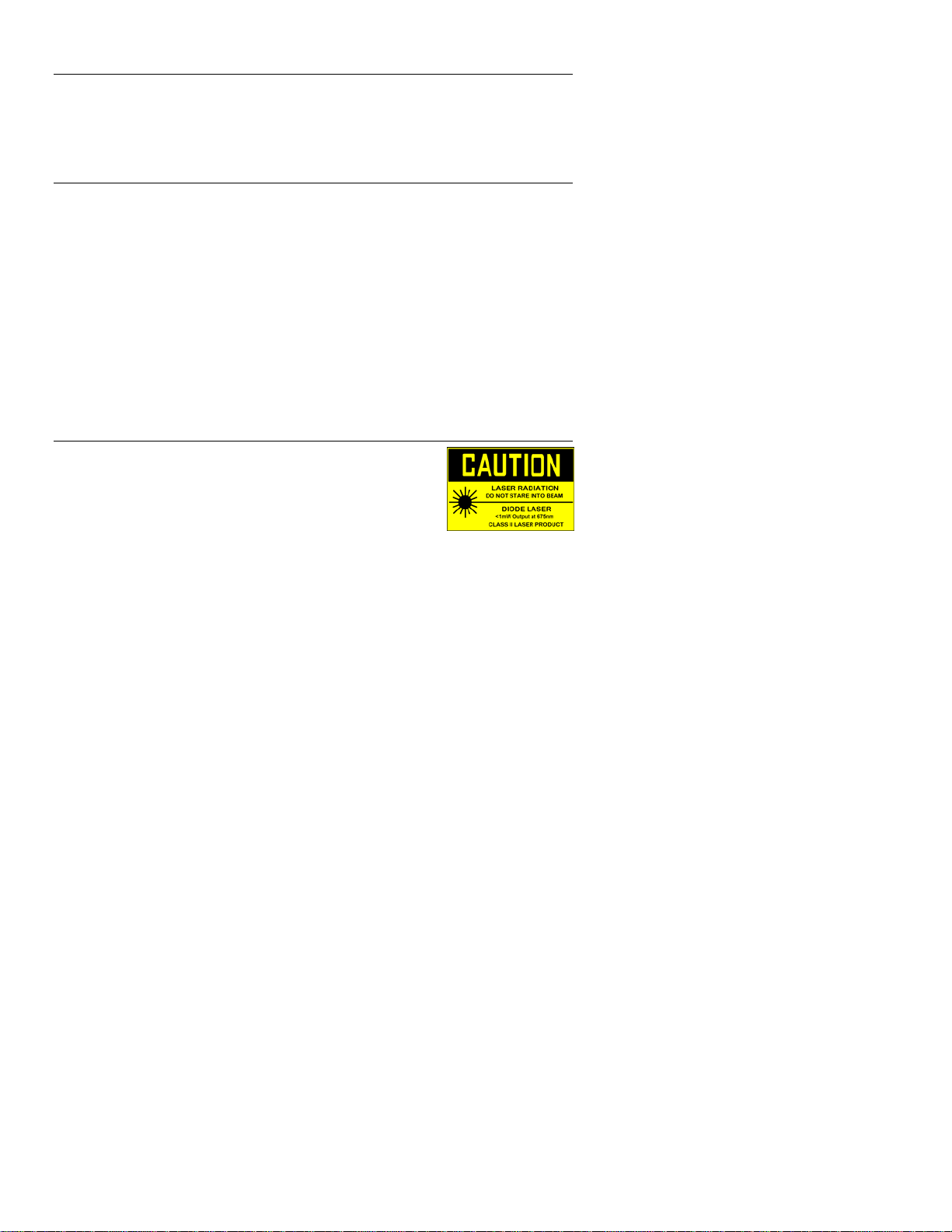
Safety
• Use extreme caution when the laser pointer beam is on
• Do not point the beam toward anyone's eye or allow the beam
to strike the eye from a reflective surface
• Do not use the laser near explosive gases or in other
potentially explosive areas
2
HD500 V3.1 12/07
Page 3
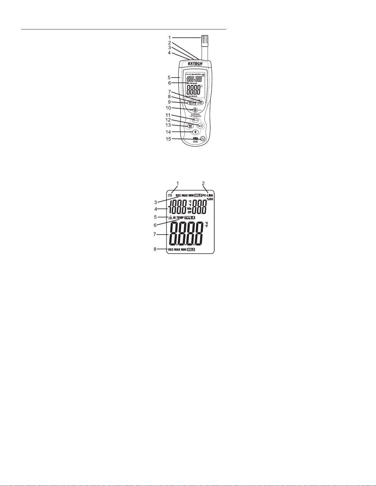
Meter Description
1. Humidity & Air Temperature Sensor
2. Type K Thermocouple input jack
3. Laser pointer beam
4. IR temperature sensor
5. USB Interface
6. LCD Display
7. Upper display HOLD button
8. Upper display Temp./Wet Bulb/Dew Point button
9. Upper display record Max/Min button
10. IR Measurement button
11. °F/°C units button
12. Lower display HOLD button
13. Lower display record Max/Min button
14. Backlight button
15. Power button
NOTE: Battery Compartment, Tilt Stand and Tripod Mount are located on the reverse
side of the meter
Display Description
1. Low Battery icon
2. PC communication icon
3. Upper display function icons
4. Upper display
5. Laser pointer icon
6. Lower display function icons
7. Lower display
8. Lower display function icons
3
HD500 V3.1 12/07
Page 4

Operation
Basic Measurements
1. Press the
2. The upper display will indicate Air Temperature, Wet Bulb Temperature or Dew Point
Temperature and % Relative Humidity.
Press the WB/DP button to toggle between Air, WB or DP.
3. The lower display will indicate Type K temperature or IR Temperature.
Press and hold the IRT button to select the IR Thermometer.
The TYPE-K function will display “-------“ if a type k probe is not inserted into the meter.
4. Press the °C/°F button to change the temperature units from °C or °F.
Non-contact IR Surface Temperature Measurements
The built-in IR sensor can remotely measure the temperature of most
surfaces. The Laser pointer allows the user to aim accurately when taking
non-contact measurements.
1. Turn ON the meter using the
2. The IR sensor and laser pointer are located at the top of the meter.
3. Point the sensor toward the surface to be measured.
4. Press and hold the IRT button to begin measuring the surface
temperature of a desired target. IR TEMP and will appear on the
display. The laser pointer will switch on to help aim the meter.
5. The measured IR surface temperature will appear on the lower display.
6. When the IRT button is released, the laser pointer will switch off and the
reading will freeze (data hold) on the display for approximately 7
seconds.
7. After the 7 second hold time the meter returns to the type k mode.
WARNING: Do not directly view or direct the laser pointer at an eye. Low power
visible lasers do not normally present a hazard, but may present some potential for
hazard if viewed directly for extended periods of time.
button to turn power on.
button.
Data Hold
1. Press the HOLD buttons (one for upper display and one for lower display) to freeze the
displayed value for the respective display. Press again to unlock the display.
2. The HOLD icon will appear on the display when the Data Hold mode is active.
4
HD500 V3.1 12/07
Page 5

MIN-MAX Recording Mode
1. Press the MAX/MIN button (one for upper display and one for lower display) to begin
recording the Maximum and Minimum reading. The REC MAX icon will appear and only
the maximum value measured will appear in the display. The display will update only if a
value higher than the currently displayed value is measured.
2. Press the MAX/MIN button again to display the minimum values. The REC MIN icon will
appear and only the minimum recorded value will appear in the display.
3. Press the MAX/MIN button again to display the currently measured values. The REC
icon will appear in the display and the Max and Min values will be stored in memory.
4. Press and Hold the MAX/MIN button for >2 seconds to exit the mode.
Auto-Power Off
The meter will automatically turn off after 15 minutes of operation if no buttons are pressed
during this period. Auto-power off can be disabled by:
1. Hold the IRT button and then press the
button to turn the power on. When “disAPO”
appears in the display, release the IRT button and the APO is disabled.
Low Battery
When the battery reaches the minimum operating voltage the battery icon will appear in
the display. Replace the 9V battery when this happens.
Battery Replacement
When the battery icon appears on the LCD, the 9V battery must be replaced.
1. The battery compartment is located on the rear of the meter.
2. Press in and down on the arrow located above the tilt stand hinge.
3. Replace the 9V battery
4. Replace the battery cover.
Backlight
Press the backlight button to turn the backlight ON or OFF.
Note: continuous use of the backlight function will reduce battery life.
USB Interface and Software
The HD500 is equipped with a communication jack on its upper left side. The supplied
communications cable connects to this jack and to a USB port on a PC. The supplied
software allows the user to view and save readings to the PC. Instructions for use and
features are detailed in the supplied software HELP utility.
5
HD500 V3.1 12/07
Page 6

InfraRed Measurement Considerations
• When taking IR measurements the meter automatically compensates for ambient
temperature changes. Note that it may take up to 30 minutes to adjust to extremely
wide ambient changes.
• Low temperature measurements quickly followed by high temperature measurements
may require several minutes to stabilize as a result of the IR sensor cooling process.
• If the surface of the object under test is covered with frost, oil, grime, etc., clean before
taking measurements.
• If an object's surface is highly reflective apply masking tape or flat black paint before
measuring.
• Steam, dust, smoke, etc. can obstruct measurements.
• To find a hot spot, aim the meter outside the area of interest then scan across (in an up
and down motion) until the hot spot is located.
• IR measurements cannot be made through glass.
IR Theory
IR thermometers measure the surface temperature of an object. The meter’s optics sense
emitted, reflected, & transmitted energy that is collected and focused onto the meter’s
detector. The meter’s circuitry translates this information into an LCD reading.
IR Field of View
Ensure that the desired target is larger than the spot size. As the distance from an object
increases, the spot size of the area measured by the meter becomes larger. The meter’s
field of view ratio is 30:1, meaning that if the meter is 30 inches (cm) from the target, the
diameter (spot) of the object under test must be at least 1 inch (cm). Refer below to the
field of view diagram.
Emissivity
Most organic materials and painted or oxidized surfaces have an emissivity of 0.95.
Inaccurate readings will result when measuring shiny or polished surfaces. To
compensate, cover the surface under test with masking tape or flat black paint. Allow time
for the tape to reach the same temperature as the material underneath then measure the
temperature of the tape or the painted surface.
6
HD500 V3.1 12/07
Page 7

Thermal Emissivity Table for Common Materials
Material Emissivity Material Emissivity
Asphalt 0.90 to 0.98 Cloth (black) 0.98
Concrete 0.94 Human skin 0.98
Cement 0.96 Leather 0.75 to 0.80
Sand 0.90 Charcoal (powder) 0.96
Earth 0.92 to 0.96 Lacquer 0.80 to 0.95
Water 0.67 Lacquer (matt) 0.97
Ice 0.96 to 0.98 Rubber (black) 0.94
Snow 0.83 Plastic 0.85 to 0.95
Glass 0.85 to 1.00 Timber 0.90
Ceramic 0.90 to 0.94 Paper 0.70 to 0.94
Marble 0.94 Chromium oxides 0.81
Plaster 0.80 to 0.90 Copper Oxides 0.78
Mortar 0.89 to 0.91 Iron Oxides 0.78 to 0.82
Brick 0.93 to 0.96 Textiles 0.90
7
HD500 V3.1 12/07
Page 8

Specifications
General Specifications
Display Dual Display Multi-function LCD with 9999 counts
Data Hold Freezes displayed reading
Sampling rate 1 reading per second
Sensors Relative Humidity: Capacitance, Air Temp: Thermistor
IR Distance to Spot ratio 30:1
IR Spectral response 6 to 14µm
IR Emissivity 0.95 fixed
MIN-MAX Record and Recall lowest and highest readings
Auto Power OFF Automatic shut off after 15 minutes (can be disabled)
PC Interface USB PC Communication with supplied software and cable for
Over range indication Dashes appears on the LCD
Low battery indication Battery symbol appears on the LCD
Power supply 9V Battery
Operating conditions Meter: 32 to 122
Dimensions / Weight Main instrument: 10.1 x 3.0 x 2" (257 x 76 x 53mm)
Weight 12.5 oz. (355g)
Range Specifications
Function Range Resolution Accuracy
Temp
(type-K)
IR Temp
Air Temp. -4 to 140°F
Wet Bulb -6.88 to 140°F
Dew Point -90.4 to 140°F
data acquisition
o
F (0 to 50oC); 80% RH max.
-148°F to -20°F
-20°F to 2501°F
-100°C to -30°C
-30°C to 1372°C
-58 to -4°F
-50 to -20°C
-4 to 932°F
-20 to 500°C
-20 to 60°C
1°≥1000
0.1°<1000
0.1°F/°C ±9.0°F / 5.0°C
0.1°F/°C ±2% reading or ±4°F/2°C
0.1°F/°C ±(2% reading + 2°F/1°C)
±(3.0% reading + 4°F)
±(3.0% reading + 2°F)
±(3.0% reading + 2°C)
±(3.0% reading + 1°C)
10% to 90% 0.1%RH ±2% RH %RH
<10% and >90% 0.1%RH ±3% RH
-21.6 to 60°C
-68 to 60°C
0.1°F/°C calculated
0.1°F/°C calculated
8
HD500 V3.1 12/07
Page 9

Warranty
EXTECH INSTRUMENTS CORPORATION warrants this instrument to be free of defects
in parts and workmanship for three (3) years from date of shipment (a six month limited
warranty applies to sensors and cables). If it should become necessary to return the
instrument for service during or beyond the warranty period, contact the Customer Service
Department at (781) 890-7440 ext. 210 for authorization or visit our website
www.extech.com for contact information. A Return Authorization (RA) number must be
issued before any product is returned to Extech. The sender is responsible for shipping
charges, freight, insurance and proper packaging to prevent damage in transit. This
warranty does not apply to defects resulting from action of the user such as misuse,
improper wiring, operation outside of specification, improper maintenance or repair, or
unauthorized modification. Extech specifically disclaims any implied warranties or
merchantability or fitness for a specific purpose and will not be liable for any direct, indirect,
incidental or consequential damages. Extech's total liability is limited to repair or
replacement of the product. The warranty set forth above is inclusive and no other
warranty, whether written or oral, is expressed or implied.
Calibration and Repair Services
Extech offers repair and calibration services for the products we sell. Extech also
provides NIST certification for most products. Call the Customer Care Department for
information on calibration services available for this product. Extech recommends that
annual calibrations be performed to verify meter performance and accuracy.
Technical support: Extension 200; E-mail: support@extech.com
Repair & Returns: Extension 210; E-mail: repair@extech.com
Product specifications subject to change without notice
For the latest version of this User’s Guide, Software updates, and other
up-to-the-minute product information, visit our website: www.extech.com
Extech Instruments Corporation, 285 Bear Hill Rd., Waltham, MA 02451
All rights reserved including the right of reproduction in whole or in part in any form.
Support line (781) 890-7440
Copyright © 2007 Extech Instruments Corporation.
9
HD500 V3.1 12/07
Page 10

10
HD500 V3.1 12/07
 Loading...