

Page 1

FiberMeter Optical Power Meter
Model #: FO600 / FO602 / FO610
Operations Guide
Firmware Revision 4.62
March 1, 2007
Page 2

Table of Contents
INTRODUCTION I-1
Why Use An Optical Fiber Power Meter? I-1
Checking Your FiberMeter Firmware Version I-1
Description I-2
Applications I-2
NOTE ON BACKLIGHT OPERATION I-3
UNIT 1 - FEATURES & FUNCTIONS 1-1
General Features - Ports 1-1
General Features - Keypad 1-1
General Features - Liquid Crystal Display (LCD) 1-2
Keyboard Entry Method 1-3
Modes of Operation 1-3
Monitor Mode 1-4
METER CONFIGURATION FUNCTIONS 1-4
Changing User Information 1-4
Changing User Name 1-4
Changing User Telephone Number 1-5
Setting User Preferences 1-5
Changing Wavelength Options 1-5
Entering Custom Wavelength 1-6
Setting Custom Wavelength 1-6
Resetting Custom Wavelength to Default 1-6
Setting Tone Detection Options 1-7
Setting LCD Contrast 1-7
Port Diagnostics 1-7
Test Download Port 1-8
Test Optical Data Port 1-8
LIGHT SOURCE MENU 1-9
UNIT 2 - SIMPLE METER 2-1
Overview 2-1
Operation 2-1
Function Options Menu 2-1
SIMPLE METER Test Procedures 2-1
SIMPLE METER - Attenuation Test 2-2
SIMPLE METER - Fiber Continuity Test / Fiber Identification 2-3
SIMPLE METER - Testing Patch Cords 2-3
SIMPLE METER - Active Equipment Measurement 2-4
SIMPLE METER - Fiber Length Measurement 2-4
SIMPLE METER - Fiber Length Measurement - Installed Link 2-5
SIMPLE METER - Fiber Length Measurement - Spool or Jumper 2-6
SIMPLE METER - MAIN MENU 2-6
UNIT 3 - CERTIFICATION METER 3-1
Overview 3-1
CERTIFICATION METER Test Procedures 3-1
MAIN MENU 3-2
MAIN MENU - FIBER LINK MENU 3-2
MAIN MENU - FIBER LINK MENU - LINK WIZARD 3-2
MAIN MENU - FIBER LINK MENU - LOAD/EDIT LINK 3-2
MAIN MENU - FIBER LINK MENU - CONFIGURE LINK 3-3
Configure Link Properties and Set Reference 3-3
Configure Link Properties and Set Reference - Manual Reference Method 3-3
Setting a Manual Reference 3-4
Setting a Manual Reference Using a Link Budget 3-4
Setting an Optical Reference by Zeroing the Light Source 3-5
MAIN MENU - FIBER LINK MENU - VIEW LINK CONFIG 3-5
MAIN MENU - FIBER LINK MENU - DELETE LINK 3-6
MAIN MENU - FIBER LINK MENU - PRINT LINK 3-6
Page 3

Table of Contents, cont.
MAIN MENU - TAKE READINGS 3-6
MAIN MENU - STORED READINGS 3-6
MAIN MENU - STORED READINGS - VIEW/EDIT/LOAD/PRN 3-7
MAIN MENU - STORED READINGS - PRINT READINGS 3-8
MAIN MENU - STORED READINGS - DELETE READINGS 3-8
MAIN MENU - STORED READINGS - DOWNLOAD DATA 3-9
MAIN MENU - METER PROPERTIES 3-9
MAIN MENU - LIGHT SOURCE MENU 3-9
MAIN MENU - TEST FIBER LENGTH 3-9
CERTIFICATION METER - Cabling Standard Certification Test 3-10
UNIT 4 - Extech Reporter Software 4-1
Overview 4-1
Installing Extech Reporter 4-1
Using Extech Reporter 4-1
Downloading Data into Extech Reporter 4-2
Viewing Extech Reporter Data - Summary View 4-2
Viewing Extech Reporter Data - Detail View 4-3
Printing Reports from Extech Reporter 4-4
Saving and Retrieving Data in Extech Reporter 4-5
Help Menu 4-5
Interpreting Extech Reporter Screens and Reports 4-5
Connector Loss 4-6
Fiber Loss 4-6
Light Source Reference Power 4-7
Measured Power 4-8
Operating Margin % 4-8
Optical Loss 4-9
Pass/Fail 4-9
Splice Loss 4-10
System Overhead 4-10
System Reference Power 4-11
Total Allowable System Loss 4-11
UNIT 5 - Appendices 5-1
Glossary 5-1
FiberMeter Specifications 5-4
Cleaning and Care Instructions
Warranty Information 5-6
Re-calibration and Repair Services 5-6
Supported Cabling Standards 5-7
Reference Cable Setup 5-8
10 Gigabit Ethernet Standard 5-9
Link Budget Calculation Worksheet
5-5
Page 4

INTRODUCTION
Why Use An Optical Fiber Power Meter?
Standards organizations such as the TIA or the IEEE provide performance standards that the cabling plant
must adhere to in order to support high-speed protocols such as Gigabit Ethernet. Fiber can be tested
against these standards, ensuring that it is able to handle a high amount of traffic with a maximum amount of
reliability.
It is standard procedure to produce a hard-copy report (or digital file) of the test results generated from
appropriate test equipment for tracking and auditing purposes. These reports can be used as verification of
compliance to performance standards in case a question comes up about the quality of an installation. These
signed documents cover the installer from liability provided that the link meets specified performance
standards.
Our optical fiber power meters are designed with cabling standards in mind because we understand the
importance of qualifying fiber installations with standards-compliant test equipment. The meter you have just
purchased prints professionally formatted reports showing the conformity to these popular industry
standards. These reports can be printed as a record of the original conformity to quality and performance set
by the standards. These documents signed by all associated parties may prove valuable in any future
disputes concerning the installation.
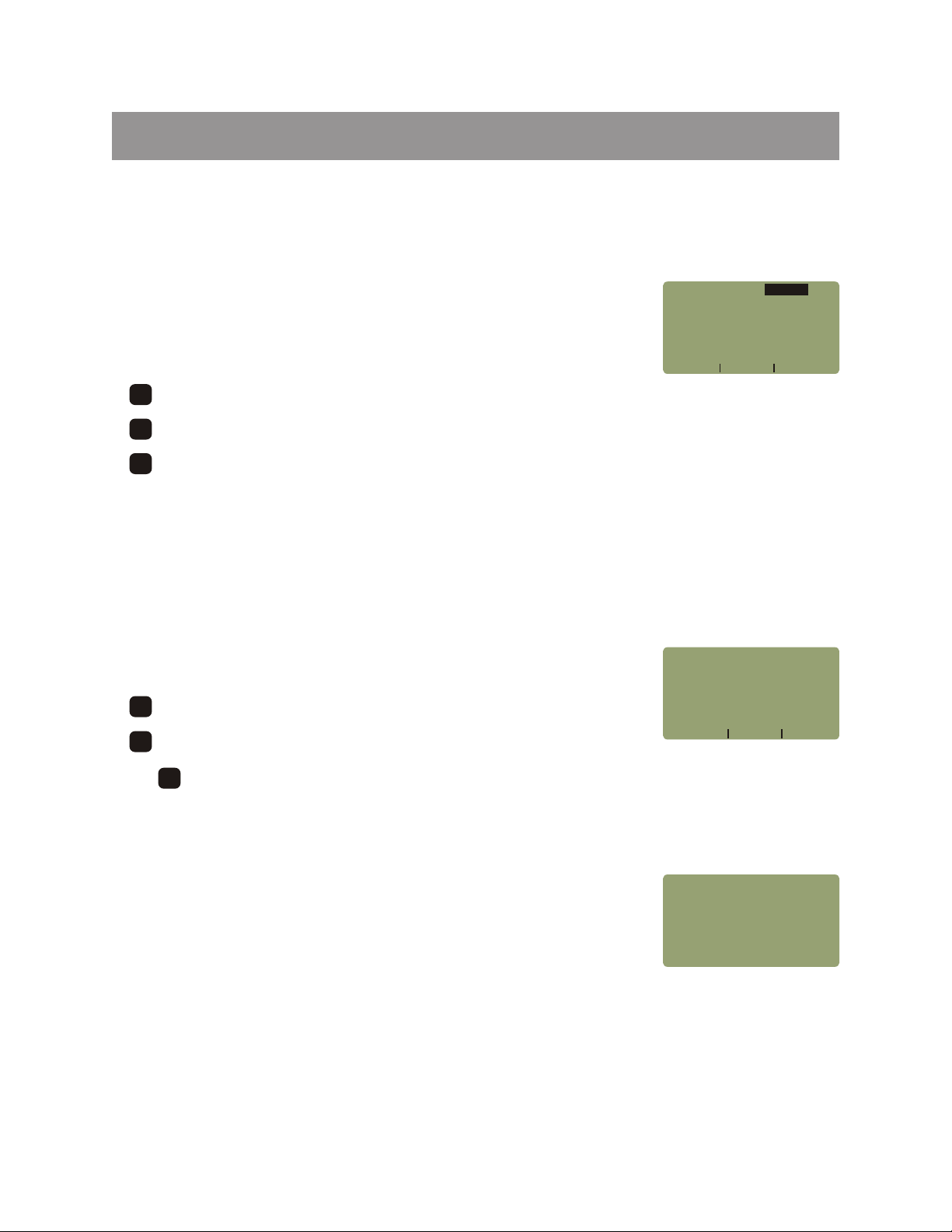
Checking Your FiberMeter Firmware Version
This manual is written for the FiberMeter firmware version 4.62. It is not valid for previously released
FiberMeter versions. Follow the instructions below to verify your firmware version.
1 - Press to start up the meter.
2 - After the initial boot-up screen, your display should look like the diagram below. This screen remains
viewable for approximately 2 seconds.
If the firmware version is not V4.62, contact Extech Instruments at 781-890-7440 for more information about
acquiring the correct version of the manual.
COMPANY NAME
COMPANY PHONE
SERIAL NUMBER
FIRMWARE VERSION
..................
............
SN:FX2xxxx
V4 62.
I-1
Page 5

INTRODUCTION
Description
The FiberMeter is a high-accuracy, high-resolution, microprocessor-controlled optical power meter. It has a
wide dynamic range making it ideal for both singlemode and multimode fiber testing.
It has an attractive handheld case made from high impact plastic, a large backlit graphic LCD, and an 18-key
keypad for easy data entry. The 2.5mm universal connector port accepts ST, SC, and FC, as well as many
other 2.5mm ferrule connectors. It will operate for over 200 hours on a standard 9-volt battery and has a builtin auto shutdown feature. A 1.25mm universal port is also included for connection to LC or other SFF
connectors.
The FiberMeter includes a built-in link wizard that helps you easily calculate optical references (link budgets)
used for fiber optic certification testing. It will store up to 1000
fiber run labels.
The stored information can be selectively viewed, edited (measured again), printed, or deleted. The meter
will print formatted reports of selected stored data directly using the built-in serial port, or all of the stored data
can be downloaded to a computer spreadsheet or our free Extech Reporter software to produce professionallooking formatted certification reports.
measured data points with descriptive link and
Applications
Attenuation Measurements. After a fiber link has been installed, optical attenuation should be measured to
determine the quality of the installation. When compared to a pre-calculated link budget, a simple calculation
can be used to determine if the link will perform as installed. See the appendix at the end of this manual for a
link budget calculation worksheet.
Fiber Network Certification Testing. The Link Wizard in the FiberMeter uses attenuation parameters from
popular cabling standards to certify fiber links. Stored data can be referenced to the standards to determine if
the link passes or fails. Stored data can be downloaded into our FREE Extech Reporter software, where
certification reports can be printed out with details or summaries of the fibers being certified.
Fiber Continuity Testing. Continuity can be measured by placing a calibrated light source on one end of the
fiber and the FiberMeter on the other end. A power reading on the liquid-crystal display (LCD) shows the
presence of optical power.
Patch Cord Testing. Fiber links that are producing incorrect results may have bad patch cords. The
FiberMeter can be used to test the attenuation of a patch cord to see if it is usable, or should be replaced.
Active Equipment Optical Power Measurements. Active equipment should be monitored periodically to test
its power levels and stability. The FiberMeter can be directly attached to this equipment via a patch cord to
check whether the transmitter is stable and within the manufacturer’s specified power range.
Length Measurement of Fiber Optic Links or Spools (optional for FO602). Generic cabling standards such as
the TIA-568 use the actual length of the cable under test to calculate loss budgets. Spool testing can verify
that the amount of fiber delivered on the spool is accurate.
I-2
Page 6

INTRODUCTION
NOTE ON BACKLIGHT OPERATION
By default, the backlight in FiberMeter series optical power meters is set to be always ON. To save power, the
backlight status may be set to OFF by following these steps below:
FROM CERTIFICATION METER
1) Press to activate the MAIN MENU.
2) Press to activate the METER CONFIG MENU.
3) Press to activate the USER PREFERENCES menu.
4) Press to set the STARTUP BACKLIGHT STATE: OFF.
5) Press twice to return to the MAIN MENU.
MENU
4
JKL
2
DEF
F2F2
DONE
FROM SIMPLE METER
1) Press to activate the MAIN MENU.
2) Press to activate the METER CONFIG MENU.
3) Press to activate the USER PREFERENCES menu.
4) Press to set the STARTUP BACKLIGHT STATE: OFF.
5) Press twice to return to the MAIN MENU.
MENU
2
DEF
2
DEF
F2F2
DONE
I-3
Page 7
UNIT 1
FEATURES & FUNCTIONS
General Features
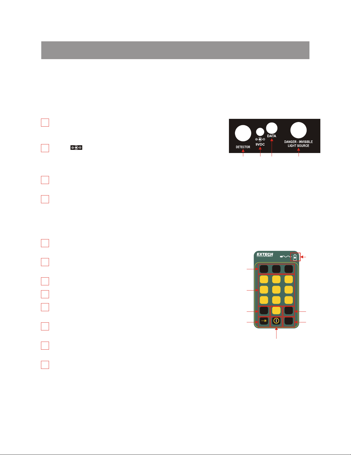
Ports
DETECTOR - houses detector port, and accepts 2.5mm cap (for ST,
1
SC, FC, plus others) or 1.25mm cap (for LC, MU, or other SFF
connectors)
9VCD - charges battery when a re-chargeable 9-volt battery is
2
in use.
charger port is in use. Failure to comply to this warning may damage
the unit or cause harm to the user.
3
DATA - downloads data from the meter to a PC via supplied 9-pin RS232 serial cable
DANGER - INVISIBLE LIGHT SOURCE - contains light source for
4
use with optical length testing feature
WARNING - Use ONLY re-chargeable batteries when
(FO602 model only)
1 2
Ports Diagram
3
4
Keypad
1
FUNCTION KEYS - activate the options on the Function Options
Menu
2
ALPHA-NUMERIC KEYS - enter letters, numbers, and symbols into
field prompts
3
MENU KEY - used to enter the menu system
4
DONE KEY - activates menu options
5
LIGHT SOURCE KEY - activates the SOURCE SETTINGS menu
when an optional light source is installed
6
POWER KEY - turns the meter ON or OFF, and toggles the backlight
ON or OFF.
7
AUTO KEY - toggles the automatic wavelength recognition mode
ON and OFF
8
BATTERY INDICATOR LED - indicates when the battery charger is
in use
OPTICAL POWER METER
1
2
3
5
F1F1
1
ABC
4
JKL
7
STU
MENU
Keypad Diagram
Fiber
F2F2
2
DEF
5
MNO
8
VWX
0
. - /
6
TestTest
DONE
AUTO
F3F3
3
GHI
6
PQR
9
8
YZ
4
7
1-1
Page 8
UNIT 1
General Features
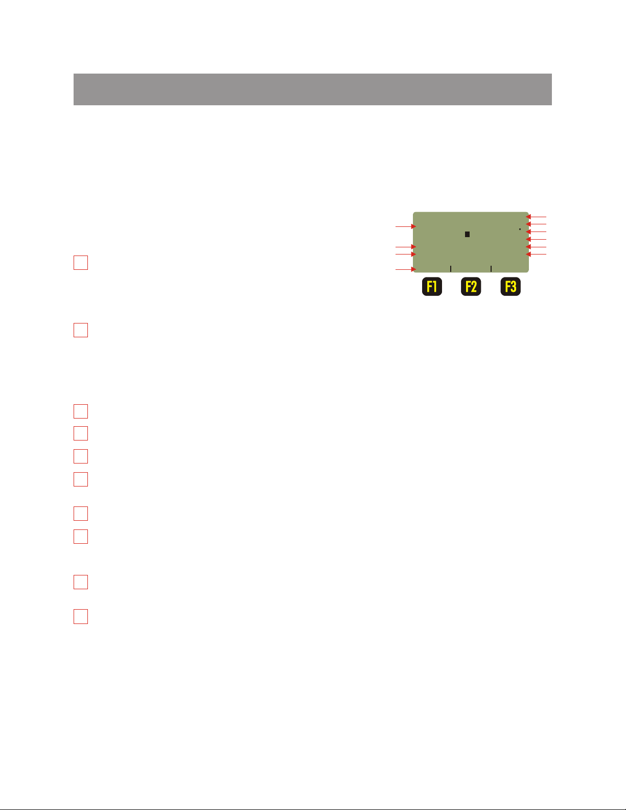
Liquid Crystal Display (LCD)
FEATURES & FUNCTIONS
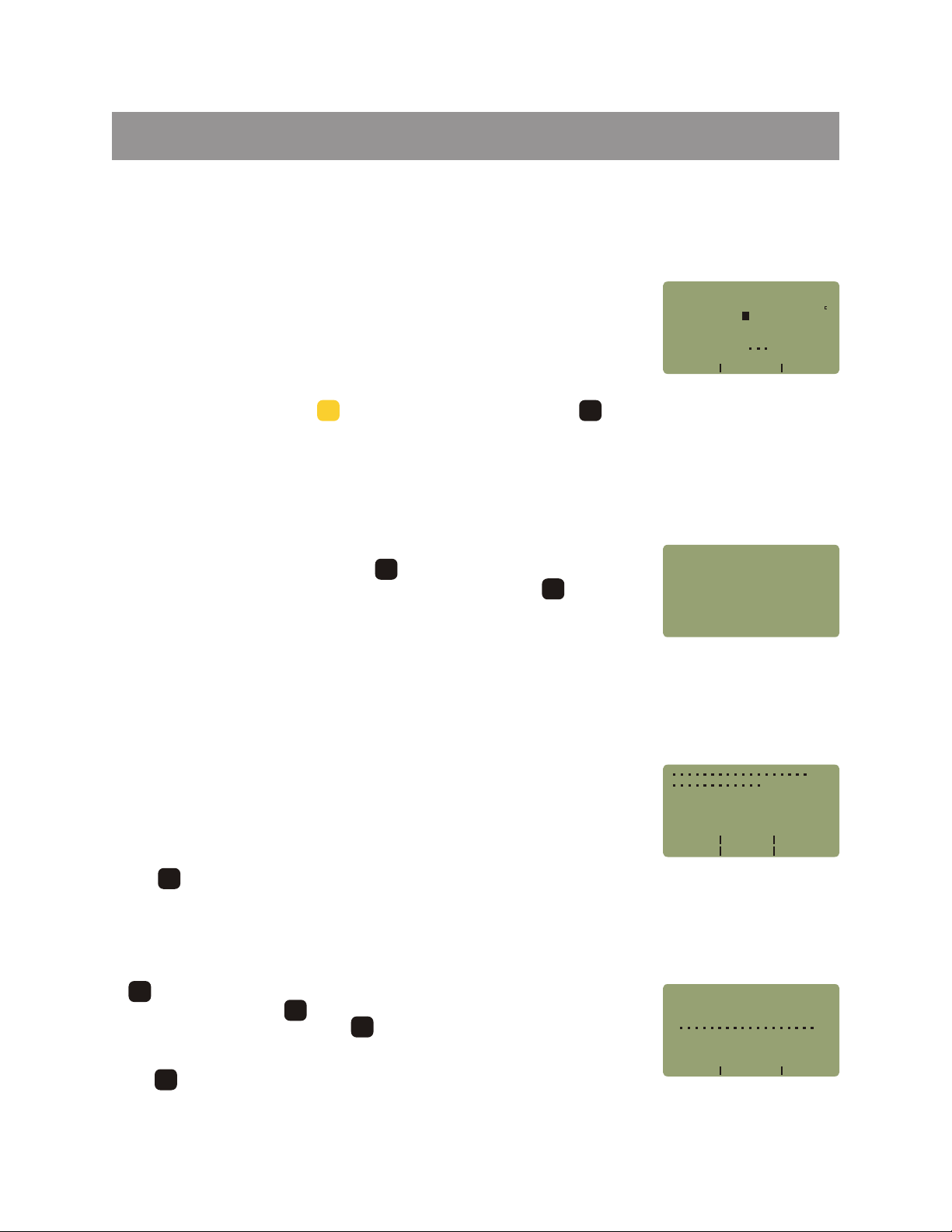
The screen at right shows information when power readings are
being taken. We will refer to this screen throughout this manual
as Immediate Mode.
1
POWER READING - shows the amount of optical power being
received by the photodetector based upon the type of power
1
-20 45
7
FIBER
8
9
LINK #1
FBR:123
_____________________
UNITS
STORE WAVE
dBm
82
68%
850nm
units currently being displayed. The display may also show
UNDER when there is no measurable optical power or OVER
when there is too much optical power to measure
2
POWER UNITS - shows the power units which are currently
being displayed
dBm - optical power in decibels relative to a milliwatt of optical
Liquid Crystal
Display (LCD)
Diagram
IMMEDIATE MODE
energy
dB - optical power in decibels relative to a previously set optical reference, also known as optical loss
uW - optical power in watts; either microwatts (uW) or milliwatts (mW)
3
TONE DETECTION - shows ‘Hz’ if a modulated signal is being detected by the meter
4
TEMPERATURE - shows current temperature in degrees (selectable Fahrenheit or Celcius)
5
BATTERY LIFE - shows the amount of remaining battery life; will flash BAT when battery is low
6
LIGHT SOURCE WAVELENGTH (only appears if optional light source is installed) - displays the current
light source wavelength output
Hz
2
3
4
5
6
10
7
LINK NAME - shows the name of the currently loaded fiber link (if shown)
8
FIBER RUN - shows the current fiber information (if shown)
FBR: - user-configurable descriptive fiber name
123 - auto-incrementing fiber number (from 1 to 999)
9
FUNCTION OPTIONS MENU - functions corresponding to the function keys on the keypad; the options
on this menu will change according to the current function
10
POWER METER WAVELENGTH - shows the currently selected wavelength (see the specifications in
the appendix at the end of this manual for a list of wavelengths); will also alternate between wavelength
and ‘AUTO’ when set to automatic wavelength detection mode
1-2
Page 9

UNIT 1
FEATURES & FUNCTIONS
Keyboard Entry Method
Several screens in the FiberMeter menu system require the user to enter some input, e.g. a fiber length
measurement or a descriptive name for a fiber run. This feature allows the FiberMeter to be more userfriendly.
Alpha-numeric Fields. These fields allow the user to enter either a number, a letter, or a special character.
This is accomplished by pressing and holding the key until the desired character appears. When the key is
released, the cursor automatically advances to the next position.
Numeric Fields. These fields are for numeric input only, e.g. fiber length, user-defined reference values, etc.
The cursor will automatically advance once a number key is pressed. Exception: some numeric operators
may be required, such as the minus sign or a decimal point. The key contains special characters. In this
case, they are treated like alpha-numeric fields.
0
. - /
Press the key when character input is complete.
DONE
Modes of Operation
As an added convenience, the FiberMeter has been designed to operate as two
different types of meters: SIMPLE METER and CERTIFICATION METER.
SIMPLE METER is used for simple optical power or attenuation (loss)
measurements. Users may set up temporary reference values for each
wavelength for quick loss readings. SIMPLE METER is covered in more detail in
Unit 2.
OPERATING
SIMPLE METER
CERTIFICATION METER
TECHNICAL SUPPORT
_____________________
NEXT
OPERATING MODE
CERTIFICATION METER is a user-friendly and powerful auto-testing fiber optic
network certification tool. Fiber links can be certified against one of many popular cabling standards, as well
as against user-defined standards. Up to 1000 data points can be stored for download to a PC. Extech
Reporter software organizes and formats these data points, and prints them into professional certification
reports. CERTIFICATION METER is covered in more detail in Unit 3.
Users may return to the OPERATING MODE menu from:
1) SIMPLE METER by pressing from the main power measurement screen, or
2) CERTIFICATION METER by pressing from the MAIN MENU.
DONE
DONE
MODE
SELECT
MENU
Extech’s Internet URL and technical support number appears when TECHNICAL SUPPORT is chosen.
1-3
Page 10
UNIT 1
Monitor Mode
FEATURES & FUNCTIONS
Monitor Mode sends absolute power measurements in a comma-delimited
format to the serial port. A terminal program is required to view data in real time,
and captured data files can be imported into a spreadsheet for charting purposes.
Monitor Mode is useful for live monitoring of a light source or fiber optic
transmitter.
To enter Monitor Mode, press while viewing a data point. Press to exit
5
MNO
DONE
Monitor Mode.
METER CONFIGURATION FUNCTIONS
Several features of the FiberMeter can be configured from the METER CONFIG
MENU. In SIMPLE METER, pressing , then <2>METER PROPERTIES will
open this menu. While in CERTIFICATION METER, press then select
<4>METER PROPERTIES.
METER CONFIG MENU is shown at right. These configuration functions are
activated by pressing the corresponding key, and are described in more detail
below.
MENU
MENU
dBm
Hz
-20 45
FIBER
LINK #1
Monitoring
_____________________
UNITS
STORE WAVE
82
68%
850nm
Monitor Mode
METER
CONFIG MENU
<1>USER
<2>USER
<3>WAVELENGTH
<4>LCD
<5>PORT
INFORMATION
PREFERENCES
CONTRAST
DIAGNOSTICS
OPTIONS
METER CONFIG
MENU
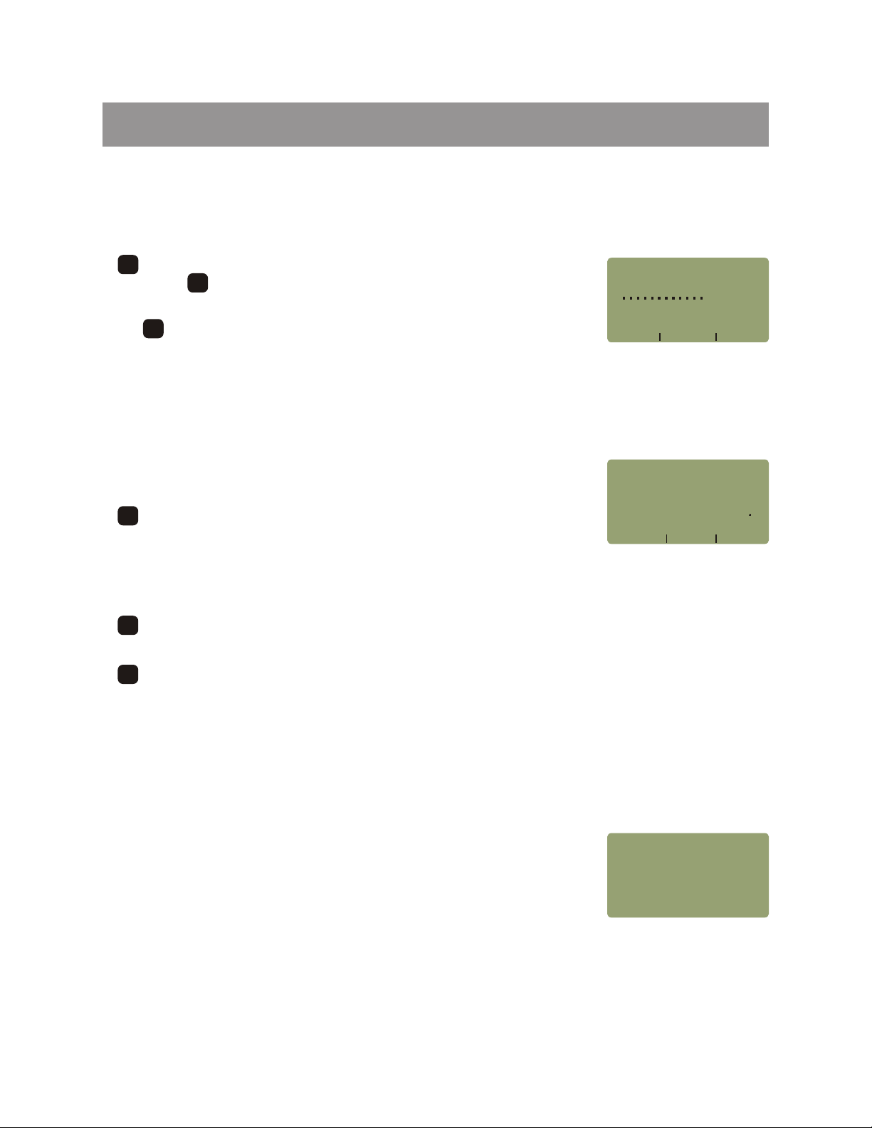
Changing User Information
<1>USER INFORMATION - this option changes the name and telephone
number of the owner of the FiberMeter.
The dots appear in these fields by default when the meter is turned on for the very
first time. These dots will be replaced with company information.
Press to return to the METER CONFIG MENU.
DONE
Changing User Name
F1F1
USER NAME - dots will first appear in the USER OR COMPANY NAME
field. Press and hold the key to backspace to the beginning of the field, then
enter the company name. Use the as a shift key for lower case letters. This
F1F1
F2F2
field allows for 18-character names.
Press when finished to return to the USER INFORMATION screen.
DONE
1-4
_____________________
USER
NAME
USER
TELE
Company Information
Screen
USER
OR COMPANY NAME:
[ ]
_____________________
<---
--->SHIFT
Change Company
Name
Page 11
UNIT 1
FEATURES & FUNCTIONS
Changing User Telephone Number
F2F2
USER TELE- dots will first appear in the PHONE NUMBER field. Press
and hold the key to backspace to the beginning of the field, then enter the
company phone number. This field allows for 12-character phone numbers.
F1F1
PHONE
NUMBER:
[ ]
Press when finished to return to the USER INFORMATION screen.
DONE
Setting User Preferences
<2>USER PREFERENCES - sets the power saving features and the displayed
temperature of the FiberMeter.
AUTO SHUTDOWN - toggles the auto-shutdown feature between ON
F1F1
and OFF. This feature is ON by default.
NOTE: the memory in the FiberMeter allows for permanent storage of data,
including reference and power readings. Data will remain in the meter, even
when the unit is powered off, until it is removed by the user.
F2F2
STARTUP BACKLIGHT STATE - determines whether the backlight is ON or OFF when the
FiberMeter is powered ON. This feature is ON by default.
TEMPERATURE UNITS - toggles between Fahrenheit (F) and Celcius (C) degrees. This feature is
F3F3
Fahrenheit (F) by default.
_____________________
<---
--->SHIFT
Change Company
Phone Number
AUTO
SHUTDOWN:
STARTUP
STATE:
TEMPERATURE
_____________________
SDWN
BACKLIGHT
ON
ON
BKLT TEMP
Set Power
Saving Features
FUNITS:
Changing Wavelength Options
<3>WAVELENGTH OPTIONS - this option is used to set various wavelengthrelated options in the FiberMeter, including setting custom wavelengths and tone
detection options.
1-5
OPTIONSWAVELENGTH
<1>CUSTOM
<2>DEFAULT
<3>TONE DETECTION
WAVELENGTH
WAVELENGTH
WAVELENGTH
OPTIONS MENU
Page 12

UNIT 1
Entering Custom Wavelength
FEATURES & FUNCTIONS
<1>CUSTOM WAVELENGTH - the FiberMeter has the capability of setting a
custom wavelength. The custom wavelength temporarily replaces 980nm, and
requires a singlemode light source tuned to -10dBm for calibration.
Enter the 3- or 4-digit custom wavelength between 700nm and 1700nm in the
entry field provided, then press to continue. An example of a custom
DONE
wavelength would be 1490nm.
Setting Custom Wavelength
Connect a -10 dBm singlemode light source of the appropriate wavelength to the
FiberMeter using a singlemode patch cord.
Press to confirm calibration. The meter will then return to the METER
F1F1
CONFIG MENU.
Resetting Custom Wavelength to Default
WAVELENGTH(nm):ENTER
(
700 to 1700nm )
[ ]
_____________________
<--- --->SHIFT
Set Custom
Wavelength
1490nm
CONNECT
SOURCE
_____________________
980nm
YES
WILL
REPLACE
1490nm
TO CALIBRATE
-10dBm
NO
Verify Custom
Wavelength
<2>DEFAULT WAVELENGTH - this WAVELENGTH OPTION resets a
previously set custom wavelength to the default wavelength of 980nm.
Press to confirm the default wavelength. The meter will then return to the
F1F1
METER CONFIG MENU.
NOTE: if the wavelength is already set to 980nm, pressing the button has no
2
DEF
effect.
1-6
RESTORE
_____________________
YES
980nm
NO
Restore Custom
Wavelength
Page 13
UNIT 1
Setting Tone Detection Options
FEATURES & FUNCTIONS
<3>TONE DETECTION - this WAVELENGTH OPTION is used to associate five
tone detection frequencies with five calibrated wavelengths, as well as set the
FiberMeter into AUTO WAVELENGTH detection mode.
The screen at right shows pre-configured tone options.
TONE - moves the tone selection highlight to the next tone.
F1F1
WAVE - toggles the wavelength of the currently selected tone.
F2F2
F3F3
AUTO - toggles the AUTO WAVELENGTH detection feature ON or OFF.
Setting LCD Contrast
<4>LCD CONTRAST - this option allows the user to set the contrast of the liquid
crystal display (LCD).
F1F1
DOWN - lightens the screen in case it is too dark
F3F3
UP - darkens the screen in case it is too light
Press to return to the METER CONFIG MENU.
DONE
300Hz
600Hz
1000Hz
1500Hz
2000Hz
AUTO
WAVELENGTH: OFF
_____________________
TONE
850nm
1310nm
1300nm
1490nm
1550nm
WAVE AUTO
Set Toning Options
NOTE: shown above is the
default tone configuration
XXXXXXXXXXXXXXXXXXXXX
XXXXXXXXXXXXXXXXXXXXX
XXXXXXXXXXXXXXXXXXXXX
XXXXXXXXXXXXXXXXXXXXX
XXXXXXXXXXXXXXXXXXXXX
_____________________
DOWN
CONTRAST
UP
Set LCD Contrast
Port Diagnostics
<5>PORT DIAGNOSTICS - this option performs diagnostic tests on the RS-232
serial port, and also the optical ports, if the optional light source is installed.
NOTE: <2>OPTICAL DATA PORT WILL ONLY APPEAR ON THE SCREEN ON
MODEL FO602
1-7
SELECT
<1>DOWNLOAD
<2>OPTICAL
PORT TO TEST
PORT
DIAGNOSTICS
PORT
DATA
PORT
Page 14
UNIT 1
Test Download Port
FEATURES & FUNCTIONS
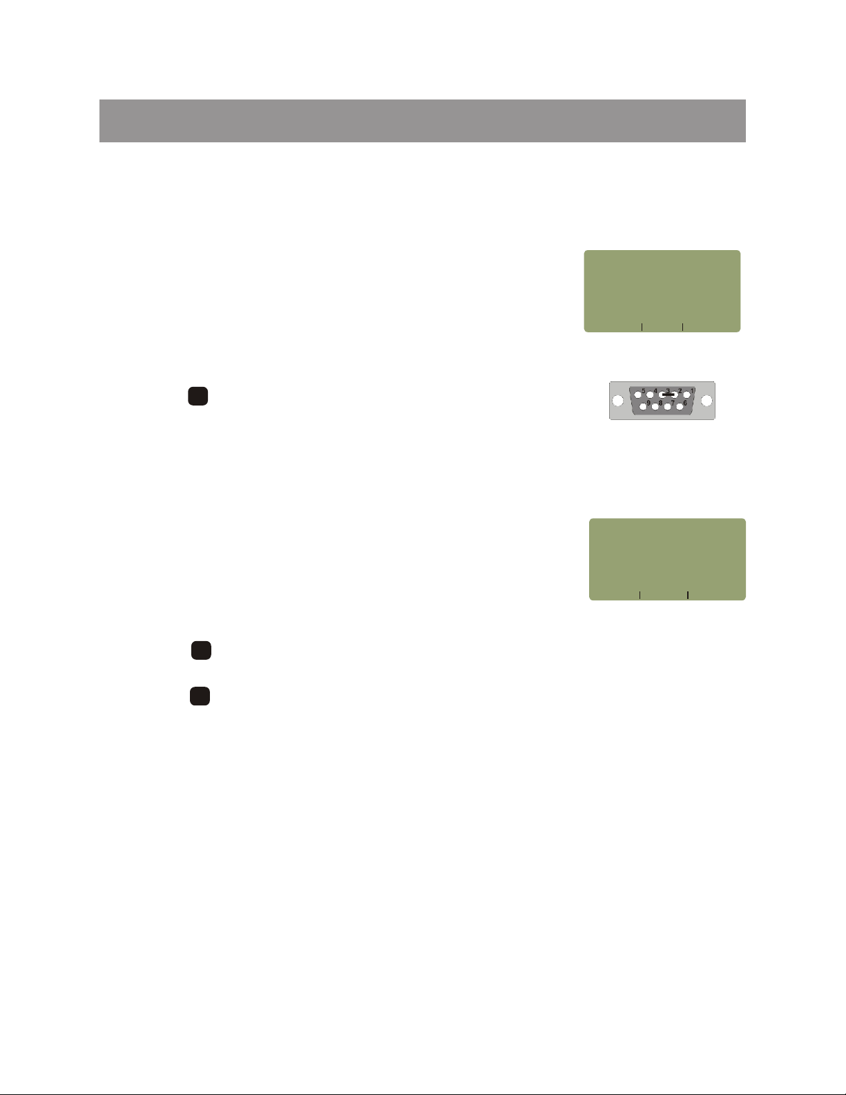
<1>DOWNLOAD PORT - this test checks the RS-232 download port for send
and receive capability.
1) Attach the download cable that came with the FiberMeter to the serial
port on the top of the unit.
2) Short pins 2 and 3 on the download cable with a short piece of wire as
shown in the diagram at right.
3) Press to confirm the test.
F1F1
If the test fails, double-check the wire that is shorting pins 2 and 3, and re-test. If
the test still fails, contact technical support.
Test Optical Data Port
<2>OPTICAL DATA PORT - this advanced diagnostic test is used during
technical support calls as a diagnostic to check the transmission status of the
detector port and the integrated light source port.
NOTE: THIS FUNCTION IS ONLY AVAILABLE ON MODEL # FO602.
1) Attach a patch cord between the detector port and source port.
2) Press to start the test. The RECEIVED DATA should begin to count
up, and for every 256 counts, the PASS NUMBER should increment by one.
F1F1
ATTACH
AND
OR
RUN
_____________________
DOWNLOAD
SERIAL LOOPBACK
SHORT PINS
SERIAL
YES NO
PORT
CABLE
2 AND 3
TEST?
RS-232 Serial Port
Test
Short Pins 2 & 3
ATTACH
CABLE
AND
NOTE:
THE
_____________________
FIBER PATCH
BETWEEN SOURCE
DETECTOR PORTS
THIS TEST TURNS
LIGHT SOURCE OFF
TEST
DONE
Optical Data Port
Test
3) Press to complete the test.
F3F3
1-8
Page 15
UNIT 1
FEATURES & FUNCTIONS
LIGHT SOURCE MENU (FO602 versions only)
In the FiberMeter model FO602, the SOURCE SETTINGS menu allows the user
to control the options of the light source. The options on this menu will change
based upon the configuration of the installed light source.
1) Press .
2) WAVELENGTH - turns the light source OFF or ON. If multiple
F1F1
SOURCE
WAVE
LENGTH
-----OFF
_____________________
WAVE
F1F1
SETTINGS
TONE AUTO
---- ---NONE OFF
TONE
F2F2
F3F3
wavelengths are present, this button will cycle through all of the available
wavelengths.
TONE - toggles the TONE option for the currently selected wavelength,
F2F2
and shows the toning frequency.
AUTO - this option sets the light source into AUTO mode when multiple
F3F3
wavelengths are present; it is deactivated for single-wavelength
configurations.
3) Press when finished.
DONE
SOURCE SETTINGS
MENU
dBm
Hz
-20
FIBER
FBR:123
_____________________
UNITS
45
LINK #1
STORE
82
68%
850
850nm
WAVE
IMMEDIATE MODE
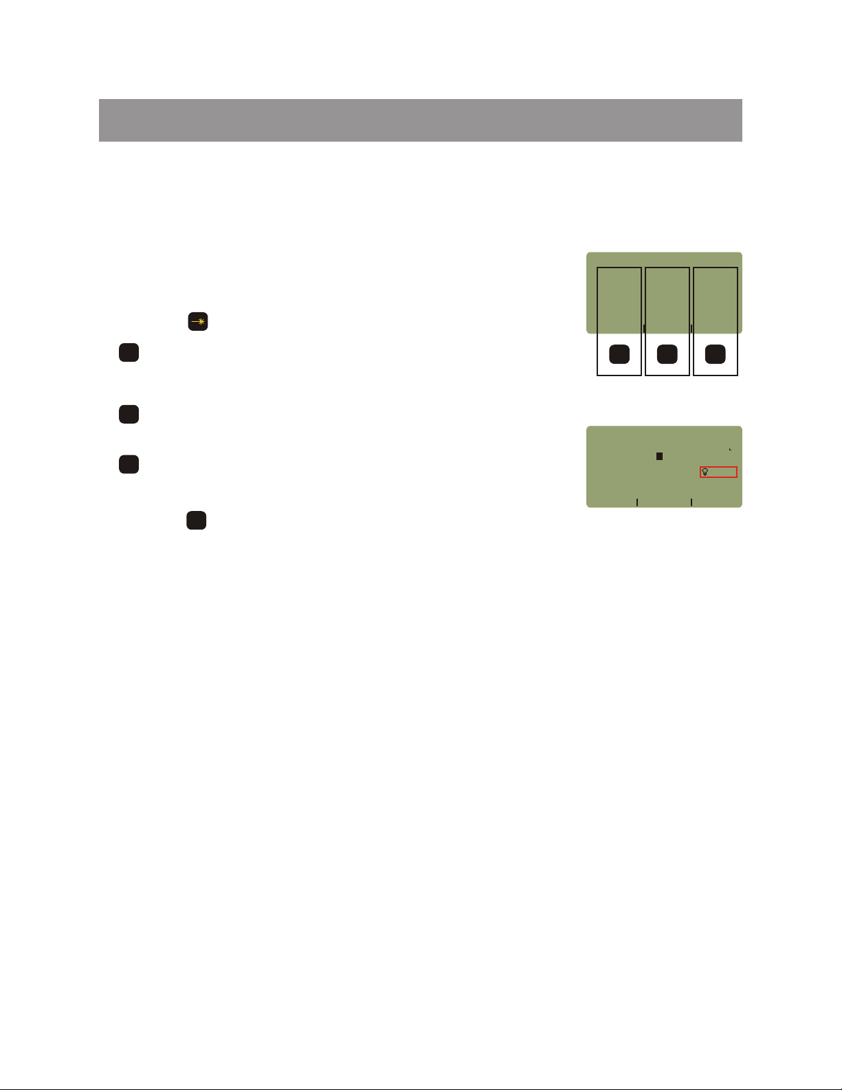
Light Source Indicator
An indicator will appear in Immediate Mode (shown in red box at right).
The lightbulb icon indicates whether the light source is in continuous wave (CW) mode (icon stays on), or in
toning mode (icon flashes). The number next to the icon shows the currently selected light source
wavelength.
1-9
Page 16
UNIT 2
SIMPLE METER
Overview
SIMPLE METER is a mode within the FiberMeter that allows the user to quickly and easily display the
attenuation of a fiber link. This mode is used when data storage is not necessary, only the most basic
functions are required: fiber loss measurement, optical power measurement, patch cord testing, or active
equipment monitoring.
Operation
1) Press the button.
2) After a few seconds, you will be prompted to choose an operating mode. When SIMPLE METER is
highlighted, press to select.
You are now ready to take fiber measurements.
F2F2
Function Options Menu
Immediate Mode will appear after the unit is booted up into SIMPLE METER.
Your display may show ‘UNDER’ - this will occur if the dustcap is still covering the
detector port.
There are three functions on the function options menu:
F1F1
UNITS - toggles the power units between dBm, dB, and microwatts;
F2F2
ZERO - sets an optical reference, or “zero” for the currently selected
wavelength; and
WAVE - toggles the wavelength between the calibrated wavelengths
F3F3
(see the specifications in the appendix for a list of calibrated
wavelengths).
SIMPLE METER Test Procedures
SIMPLE METER can be used for several different types of tests. These tests include:
Attenuation Measurement
Fiber Continuity Testing
Patch Cord Testing
Active Equipment Measurement
Optical Fiber Length Measurement (light source versions only)
dBm
-20
_____________________
UNITS
F1F1
Toggle
Power
Units
45
ZERO
F2F2
ZERO
Current
Wavelength
82
68%
850nm
WAVE
F3F3
Toggle
Wave
Lengths
Each of these tests will be described in more detail in this unit.
2-1
Page 17

UNIT 2
SIMPLE METER
SIMPLE METER - Attenuation Test
After a fiber link has been installed, optical attenuation (or loss) should be measured to determine the quality
of the installation. When compared to a pre-calculated link budget, a simple comparison of power values can
be used to determine if the link will perform as installed. A light source and two patch cords are also required
for this test. Use the following steps to perform an attenuation test in SIMPLE METER:
Calculate Maximum System Attenuation.
1) Use the link budget calculation worksheet at the end of this manual to calculate the Maximum System
Attenuation. This is the first section on the worksheet.
2) Record the Maximum System Attenuation.
Set the optical reference (or ”ZERO”).
3) Power on the FiberMeter and select SIMPLE METER.
4) Power on the light source being used for the test, and allow it to warm up according to manufacturer’s
specifications.
5) Set the FiberMeter and light source to matching wavelengths.
6) Connect the FiberMeter to the light source using a single patch cord of the appropriate type. The
core size of the patch cord should match the core size of the fiber link under test. If the fiber link under
test is multimode, the patch cord must be wrapped and secured around a mandrel. Please see the
appendix at the end of this manual for more information about setting optical references.
7) Press or to set the optical reference. The power units will automatically change to dB, and
the power reading should be very close to 0.00 dB. The optical reference in dBm will also appear
below the power reading.
NOTE: the memory in the FiberMeter allows for permanent storage of data, including reference and
power readings. Data will remain in the meter, even when the unit is powered off, until it is removed
by the user.
F2F2
0
. - /
Measure attenuation (or loss) of the fiber link under test.
8) Disconnect the patch cord from the FiberMeter, taking great care to
leave the patch cord connected to the light source.
9) Take the FiberMeter and light source to opposite ends of the fiber link
under test.
10) Connect the FiberMeter and light source to the corresponding fiber
connector using appropriate patch cords.
11) Record the power value that appears in the upper left hand corner of the
display without the minus (-) sign. This is the amount of loss across the
link.
12) Remove the patch cords from the fiber connector.
13) Repeat steps 10 through 12 for each fiber in the fiber link under test.
Repeat this procedure for each wavelength to be tested.
Interpreting the results.
Compare the Total System Attenuation from the link budget to the actual recorded loss. If the Maximum
System Attenuation exceeds the actual recorded loss, the link passes.
For example, if the Maximum System Attenuation is 2.0 dB, and the actual recorded loss is 1.54 dB (like the
display above), then the link is said to pass, and has a margin of 0.46 dB.
-
(-20 12dBm Ref)
_____________________
UNITS
Optical Loss
Displayed in dB
1
ZERO
54
dB
82
68%
850nm
WAVE
2-2
Page 18

UNIT 2
SIMPLE METER
SIMPLE METER - Fiber Continuity Test / Fiber Identification
A fiber continuity test determines if optical power can be passed through the entire fiber link, and can also be
used as a simple way to identify fibers. A light source is also required for this test.
Use the following steps to perform an fiber continuity test in SIMPLE METER:
1) Power on the FiberMeter and select SIMPLE METER.
2) Power on the light source being used for the test.
3) Set the FiberMeter and light source to matching wavelengths.
4) Take the FiberMeter and light source and connect them to opposite ends of the fiber under test.
The FiberMeter will display either a power level (which means continuity has been achieved), or ‘UNDER’
when it cannot detect any optical power. ‘UNDER’ can mean one of the following:
a) there is too much attenuation in the link (e.g. broken fiber, excessive length, dirty
connections, microbends, etc.);
b) the FiberMeter is not connected to the correct fiber; or
c) the light source is powered off.
To use the FiberMeter as a fiber identifier, follow the steps above and connect the FiberMeter to each fiber
until a power reading appears.
SIMPLE METER - Testing Patch Cords
Poor quality patch cords can cause instability in fiber optic attenuation tests. The FiberMeter can be used to
determine if the patch cord is of sufficient quality to be used for fiber optic attenuation tests, or whether it
should be replaced. A light source is also required for this test.
Use the following steps to test a patch cord in SIMPLE METER:
1) Power on the FiberMeter and select SIMPLE METER.
2) Power on the light source being used for the test, and allow it to warm up according to the
manufacturer’s specifications.
3) Set the FiberMeter and light source to matching wavelengths, and ensure that the FiberMeter is
set to dBm mode.
4) Clean the connectors of the patch cord under test, and connect the FiberMeter and light source to
the opposite ends of the patch cord.
5) Consult the manufacturer’s specifications for the light source’s calibrated power level, and compare
this number to the power level displayed on the FiberMeter.
Quality patch cords will produce very little loss, so the power levels compared in step 5 should be fairly close,
usually within 0.3 dB. Consider replacing the patch cord if the loss of the patch cord exceeds 0.3 dB.
2-3
Page 19

UNIT 2
SIMPLE METER
SIMPLE METER - Active Equipment Measurement
Active equipment should be monitored periodically to test its power levels and stability. The FiberMeter can
be directly attached to this equipment via a patch cord to check whether the transmitter is stable and within the
manufacturer’s specified power range.
NOTE: maximum transmitter output power exceeding the high end of the FiberMeter measurement range
could damage the photodector in the FiberMeter. If this is the case, a fiber optic attenuator will be necessary
to attenuate the signal sufficiently. Consult the manufacturer’s specification sheet for more information.
Use the following steps to measure the optical power of active equipment in SIMPLE METER:
1) Power on the FiberMeter and select SIMPLE METER.
2) Power on the active equipment to be tested.
3) Set the FiberMeter to match the output wavelength of the active equipment, and ensure that the
FiberMeter is set to dBm mode.
4) Connect the FiberMeter to the active equipment with a patch cord of the appropriate type.
5) Consult the active equipment manufacturer’s specifications to determine the correct power level of
the transmitter, and compare this number to the displayed optical power.
SIMPLE METER - Fiber Length Measurement
NOTE: THIS FUNCTION IS ONLY AVAILABLE FOR MODEL FO602.
The FiberMeter uses a loop-back method to measure the length of a fiber link. Use the following steps to
perform the length test:
1) Power ON the FiberMeter, and select SIMPLE METER.
2) Press to enter the MAIN MENU.
3) Select TEST FIBER LENGTH by pressing .
MENU
4
JKL
4) At the SELECT TEST TYPE menu, choose the menu option that best
matches the configuration of the fiber under test.
1
ABC
INSTALLED LINK - measures the end-to-end length of an installed fiber
cable, which is useful for calculation of loss budgets that are based on length (requires two fibers)
2
SPOOL OR JUMPER - measures the length of a spool of fiber or a test jumper
DEF
3
ABORT TEST - returns the user to the previous menu
GHI
SELECT
<1>
<2>
<3>
TEST TYPE
INSTALLED LINK
SPOOL OR JUMPER
ABORT TEST
2-4
Page 20

UNIT 2
SIMPLE METER
SIMPLE METER - Fiber Length Measurement - Installed Link
1) Connect the detector port and light source port to two fibers in the link via
patch cords.
2) On the other end of the link, connect the same two fibers with a single
patch cord, thus creating a loop.
3) Once the patch cords are connected as shown in the diagram below,
press or to run the LENGTH TEST.
DONE
F1F1
Installed Link Test
FIBER A
(FIBER
PATCH
FIBER B
END
_____________________
DONE
PAIR REQUIRED)
FIBER A TO
AT THE FAR
OF THE
FIBER B
LINK.
CONNECT
^ ^
CONNECT
^ ^
FIBER A
(FIBER
PAIR REQUIRED)
PATCH
FIBER ATO
FIBER B
AT THEFAR
END
OF THE
LINK.
_____________________
DONE
FIBER B
Symbolic
Fiber
Link
4) After the length test is complete, the fiber length will be displayed in
meters, and the index of refraction used for the test is shown.
5) Three options are available once the length measurement is complete:
F1F1
TEST - perform another length measurement
F2F2
DONE - return to the MAIN MENU
F3F3
INDEX - change the index of refraction
INDEX OF REFRACTION
FIBER LENGTH
01000
1550nm
_____________________
TEST
F1F1
Measure
Another
Installed
Link
+/-3
METERS
Index(n)=1
DONE INDEX
F2F2
Return to
MAIN
MENU
F3F3
Change
Index of
Refraction
490
Index of refraction (IOR) is an expression of the speed of light in the optical fiber
and is used to calculate the length. Since IOR varies from cable to cable, the FiberMeter allows the user to
change the IOR to match the cable under test, ensuring the most accurate length measurement. The IOR is
typically between 1.400 and 1.600, and can be found on the cable manufacturer’s specification sheet.
2-5
Page 21

UNIT 2
SIMPLE METER
SIMPLE METER - Fiber Length Measurement - Spool or Jumper
1) Connect the detector port and light source port to the terminated ends of
a patch cable or fiber spool as shown below.
2) Once the patch cable or spool is connected as shown in the diagram
below, press or to run the LENGTH TEST.
3) After the length test is complete, the fiber length will be displayed in
meters, and the index of refraction used for the test is shown.
CONNECT
^ ^
END A
PLACE
BOTH ENDS
THE FIBER
INTO THE
METER
CONNECTORS
_____________________
DONE
F1F1
END B
OF
DONE
Jumper Test
CONNECT
^ ^
END A
PLACE
BOTH ENDS
THE FIBER
INTO THE
METER
CONNECTORS
_____________________
DONE
END B
OF
Spool Test
CONNECT
^ ^
END A
PLACE
BOTH ENDS
THE FIBER
METER
CONNECTORS
_____________________
DONE
END B
INTO THE
OF
4) Three options are available once the length measurement is complete:
F1F1
TEST - perform another length measurement
F2F2
DONE - return to the MAIN MENU
F3F3
INDEX - change the index of refraction
INDEX OF REFRACTION
Index of refraction (IOR) is an expression of the speed of light in the optical fiber
and is used to calculate the length. Since IOR varies from cable to cable, the
FiberMeter allows the user to change the IOR to match the cable under test,
ensuring the most accurate length measurement. The IOR is typically between
1.400 and 1.600, and can be found on the cable manufacturer’s specification sheet.
SIMPLE METER - MAIN MENU
Pressing will enter the MAIN MENU.
<1>TAKE READINGS - return to Immediate Mode.
<2>METER PROPERTIES - see page 1-4.
<3>SOURCE CONTROL - see page 1-9.
<4>TEST FIBER LENGTH - see page 2-4.
MENU
FIBER LENGTH
02000
1550nm
_____________________
TEST
F1F1
Measure
Another
Installed
Link
<1>TAKE
<2>METER
<3>SOURCE
<4>TEST
+/-6
METERS
Index(n)=1
DONE INDEX
F2F2
Return to
MAIN
MENU
MAIN
MENU
READINGS
PROPERTIES
CONTROL
FIBER LENGTH
490
F3F3
Change
Index of
Refraction
NOTE: OPTIONS 3 AND 4 WILL ONLY APPEAR FOR MODEL FO602.
2-6
Page 22

UNIT 3
CERTIFICATION METER
Overview
Certification Meter allows the user to store data points for the purpose of certifying fiber links against known
industry cabling standards; EIA/TIA 568, ISO/IEC 11801, and Gigabit Ethernet are some examples. A userfriendly link configuration wizard is provided to enter fiber link parameters, which are used to calculate
reference values for easy PASS/FAIL readings.
The FiberMeter is capable of certifying and storing up to 1000 data points with user-configurable fiber labels.
Data points are downloaded into our free Extech Reporter Windows-compatible software for organizing data
points and printing professional certification reports.
Operation
1) Press the button.
2) After a few seconds, you will be prompted to choose an operating mode. Highlight “CERTIFICATION
METER” and press to select.
3) From the START MENU, you may either enter <1>LINK WIZARD (see page 3-2), <2>TAKE
READINGS, or enter <3>MAIN MENU (see below).
F2F2
CERTIFICATION METER Test Procedures
CERTIFICATION METER is designed to certify fiber links against popular cabling standards. An easy to use
Link Wizard is provided to walk the user through the certification setup process.
All of the tests listed in SIMPLE METER can also be done in CERTIFICATION METER, as well as three
additional advanced test methods:
Cabling Standard Certification Test
Manual Link Budget Test
Manual Reference Test
Manual Link Budget Test and Manual Reference Test are only recommended for users who have a firm grasp
of calculating link budgets manually.
3-1
Page 23

UNIT 3
CERTIFICATION METER
MAIN MENU
The MAIN MENU activates the advanced functions of the FiberMeter. To open
the MAIN MENU, press and it will appear as shown as the figure at the right.
These functions are activated by pressing the corresponding key, and are
described in more detail below.
NOTE: OPTIONS 5 AND 6 WILL NOT APPEAR IF THE OPTIONAL LIGHT
SOURCE IS NOT INSTALLED.
MENU
MAIN
<1>FIBER
<2>TAKE
<3>STORED
<4>METER
<5>SOURCE
<6>TEST
MAIN MENU
MENU
LINK
SETUP
READINGS
READINGS
PROPERTIES
CONTROL
FIBER
LENGTH
MAIN MENU - FIBER LINK MENU
<1>FIBER LINK SETUP - enters the FIBER LINK MENU. This menu allows the
user to configure and manage fiber links in the FiberMeter. The meter can store
up to eight separate fiber link configurations. The parameters contained in each
fiber link apply to all data points stored while that link was loaded.
FIBER
<1>LINK
<2>LOAD/EDIT
<3>CONFIGURE
<4>VIEW
<5>DELETE
<6>PRINT
WIZARD
LINK
LINK
LINK
MENULINK
LINK
LINK
CONFIG
FIBER LINK MENU
MAIN MENU FIBER LINK - MENU - LINK WIZARD
This menu option runs the Link Wizard. See the section “CERTIFICATION METER - Cabling Standard
Certification Test” in this unit for instructions on running the Link Wizard.
MAIN MENU FIBER LINK - MENU - LOAD/EDIT LINK
1)
From the FIBER LINK MENU, press to LOAD/EDIT the link.
2) From
the STORED LINKS menu, highlight the link name you wish to use.
2
DEF
The currently loaded link is denoted by an asterisk.
NOTE: take care to NOT overwrite a previously configured link
unless it is no longer needed.
3) Press to set the link information.
4) Edit the LINK NAME by pressing . It is recommended to change the
F3F3
F1F1
link name to better describe the link. The link name field can support up
to 17-character names. Press when finished.
5) Edit the DATE by pressing . It is of vital importance to change the
DONE
F2F2
date using the format MM-DD-YY. If the date is entered incorrectly,
or not entered at all, Extech Reporter will display an incorrect date on the
software and reports. Press when finished entering the date, then
press again to continue.
DONE
DONE
STORED
*
Fiber Link #1
Fiber Link #2
Fiber Link #3
Fiber Link #4
_____________________
NEXT
LINKS
SELECT
RENAME
STORED LINKS
MENU
CORP.
ACME
02-26-07
_____________________
LINK
NAME
DATE
Link Information
6) Press to load the link.
F2F2
3-2
Page 24

UNIT 3
CERTIFICATION METER
MAIN MENU - FIBER LINK MENU - CONFIGURE LINK
From the STORED LINKS menu, highlight the link name you wish to use. The
currently loaded link is denoted by an asterisk.
NOTE: take care to NOT overwrite a previously configured link unless it is no
longer needed.
STORED
*
Fiber Link #1
Fiber Link #2
Fiber Link #3
Fiber Link #4
_____________________
NEXT
SELECT
STORED LINKS
MENU
Configure Link Properties and Set Reference
There are three different test methods used to configure a link:
<1>USE A STANDARD TO CERTIFY LINK - this is the same as running the Link
Wizard. See the section “CERTIFICATION METER - Cabling Standard
Certification Test” in this unit for instructions.
<2>MANUAL REFERENCE - see below
<3>ZERO LIGHT SOURCE - see page 3-5
SELECT A TEST METHOD
<1>USE
<2>MANUAL
<3>ZERO
A STANDARD TO
CERTIFY
LINK BUDGET
LIGHT SOURCE
Select a Test
Method
Configure Link Properties and Set Reference - Manual Reference Method
LINKS
RENAME
LINK
REFERENCE/
Wave
850nm
980nm
WAVE
R(dBm)
+00 00 -00 01
+00 00 -00 01
+00 00 -00 01
MANUAL
REF
Manual references are used to configure the FiberMeter with custom link loss
requirements.
There are two types of manual reference methods: Link Budget and Manual
Reference. Each of these methods are recommended for advanced users only.
The Wave column shows the wavelengths available for referencing.
1300nm
_____________________
LENGTH
Wavelength Reference
Screen
The R(dBm) column shows the light source reference power level in dBm. By
default, this shows +00.00dBm.
The LB(dB) column shows the manually-set link budget in dB. By default, this shows -00.01 dB.
WAVELENGTH - scrolls between the wavelengths in the FiberMeter. The currently selected
F1F1
wavelength is highlighted.
MANUAL REF - allows the user to manually set a reference level. See page 3-4 for instructions.
F2F2
F3F3
LINK BUDGET - allows the user to manually set their own link budget. See page 3-4 for instructions.
3-3
LB(dB)
LINK
BUDGET
Page 25

UNIT 3
CERTIFICATION METER
Setting a Manual Reference
NOTE: this method is recommended for advanced users only.
Manual Reference Method sets an optical reference by allowing the user to input
an absolute optical power level (in dBm).
1) Connect a light source of the appropriate wavelength to the FiberMeter,
and power on the light source. Remember to allow the light source to
warm up according to manufacturer’s specifications.
Wave
R(dBm)
850nm
+00 00 -00 01
980nm
+00 00 -00 01
WAVE
-25 00 -00 011300nm
MANUAL
REF
_____________________
LENGTH
LB(dB)
LINK
BUDGET
Wavelength Reference
Screen
2) Using the key, scroll to the appropriate wavelength.
3) Press . The actual optical power being received by the FiberMeter will be shown in the entry
F1F1
F2F2
field. Backspace over this number to enter the desired reference level in dBm. Follow steps 2 & 3 for
each wavelength, then press to continue.
DONE
The Wavelength Reference Screen will now show the optical reference as previously entered. Readings may
be now stored as normal.
Setting a Manual Reference Using a Link Budget
Wave
850nm
980nm
WAVE
R(dBm)
+00 00 -00 01
+00 00 -00 01
-19 65 +04 001300nm
MANUAL
REF
Screen
NOTE: this method is recommended for advanced users only.
Link Budget Method sets an optical reference by adding a pre-calculated link
budget (in dB) to the optical power from a light source.
1) Connect a light source of the appropriate wavelength to the FiberMeter,
and power on the light source. Remember to allow the light source to warm up
_____________________
LENGTH
Wavelength Reference
according to manufacturer’s specifications.
2) Using the key, scroll to the appropriate wavelength.
3) Press to enter the pre-calculated link budget. Backspace over the characters in the entry field
F1F1
F3F3
and type the amount of link budget (for example, 4.00). Follow steps 2 & 3 for each wavelength, then
press to continue.
DONE
LB(dB)
LINK
BUDGET
The Wavelength Reference Screen will now show the light source reference level as well as the link budget.
For example: a 1300nm light source is outputting -19.65 dBm and the pre-calculated link budget is 4.00 dB.
The PASS/FAIL threshold would then be -23.65 dBm.
Readings may be now stored as normal.
3-4
Page 26

UNIT 3
CERTIFICATION METER
Setting an Optical Reference by Zeroing the Light Source
This method allows the user to “zero” the light source for the purpose of viewing
optical attenuation values, or loss, in Immediate Mode.
CONNECT
850nm
1) Connect a light source of the appropriate wavelength to the FiberMeter,
and power on the light source. Remember to allow the light source to
warm up according to manufacturer’s specifications.
2) Using the key, change to the appropriate wavelength.
3) Press to “zero” the light source power. Press to continue.
F1F1
F2F2
DONE
Optical loss may be viewed in Immediate Mode by setting the power units to dB. Readings may now be stored
as normal.
NOTE: zeroing the light source can also be done from Immediate Mode by pressing .
MAIN MENU - FIBER LINK MENU - VIEW LINK CONFIG
Users may view the configuration of links in the FiberMeter.
1) From the FIBER LINK MENU, press to VIEW LINK CONFIG.
2) Highlight and select the link to view from the STORED LINKS
menu.
The link configuration will appear on the display. If the link was stored by using
the Link Wizard, a display similar to the one at the right will appear. The items on
the display are explained below:
4
JKL
SOURCE
_____________________
WAVE
Confirmation Screen
0
. - /
ACME
TIA-568B
FIBER
LENGTH
2
WAVELENGTHS:
850nm
Link Configuration
ZERO
Zero Reference
CORP.
3/CAN-T529
62 5um MM
CONN 0 SPLICES
1000 METERS
1300nm
Screen
ACME CORP. - link name
TIA-568B.3/CAN-T529 - fiber cabling standard
FIBER = 62.5um MM - fiber type
LENGTH = 1000 METERS - fiber length
2 CONN 0 SPLICES - number of connections and splices
WAVELENGTHS: 850nm 1300nm - wavelengths used with standard
If the link was stored by a manual reference method, or is not in use, the display will say ALL MANUAL
REFERENCES.
DONE
Press to return to the FIBER LINK MENU.
3-5
Page 27

UNIT 3
CERTIFICATION METER
MAIN MENU - FIBER LINK MENU - DELETE LINK
At times, it may be necessary to delete a link’s configuration in order to use it for a
new link. This process will delete the link information and all readings that were
stored while this link was loaded. The following steps show how to delete a link:
1) From the FIBER LINK MENU, press .
MNO
5
2) Highlight and select the link to delete.
DELETE
STORED
ACME
_____________________
LINK
INFO.
READINGS
CORP.
YES NO
FOR:
Delete Link
AND
Confirmation Screen
3) Press to confirm deletion, and return to FIBER LINK MENU.
F1F1
NOTE: once this information is deleted from the FiberMeter, it can no longer be retrieved. Double-check to
ensure that the link is no longer needed before confirming deletion.
MAIN MENU - FIBER LINK MENU - PRINT LINK
The data points stored for particular links can be downloaded to the serial port in
an easy-to-read format. This data can be viewed and captured to file by terminal
programs such as HyperTerminal for Windows.
1) From the FIBER LINK MENU, press .
PQR
6
2) Highlight and select the link to print.
The display will show a confirmation, then will return to the FIBER LINK MENU.
PRINTING
Link Printing
Confirmation Screen
MAIN MENU - TAKE READINGS
<2>TAKE READINGS - returns the user to Immediate Mode, where readings can be stored for the currently
loaded link.
MAIN MENU - STORED READINGS
<3>STORED READINGS - opens the STORED READINGS menu, which is
used to manage the data stored in the FiberMeter.
NOTE: the memory in the FiberMeter allows for permanent storage of data,
including reference and power readings. Data will remain in the meter, even
when the unit is powered off, until it is removed by the user.
STORED READINGS
<1>VIEW/EDIT/LOAD/PRN
<2>PRINT
<3>DELETE
<4>DOWNLOAD
BYTES
READINGS
READINGS
DATA
FREE 3071
STORED READINGS
MENU
3-6
Page 28

UNIT 3
CERTIFICATION METER
MAIN MENU - STORED READINGS - VIEW/EDIT/LOAD/PRN
<1>VIEW/EDIT/LOAD/PRN - opens a data point review screen. This first
appears showing the first data point in memory. Information about the data point
includes:
Link Name (ACME CORP.)
Fiber Name and Number (FBR:1)
Fiber Type (INDOOR SM)
Wavelength (1310nm)
ACME CORP.
FBR:1
TYPE:INDOOR
WAVE:1310nm
ABS:-10
REL:-1
_________NEXT________
NAME
98dBm
98dB
RUN
SM
PASS
0=LOAD
5=EDIT
7=PRNT
WAVE
Data Point Review
Screen
Absolute Optical Power (-10.98dBm)
Relative Power (-1.98dB)
Test Result (PASS)
Several control functions can be performed from this screen. The function keys are used to navigate among
the stored data.
F1F1
NEXT NAME - scrolls through all of the different fiber names stored in the FiberMeter.
F2F2
NEXT RUN - scrolls through the data points stored with the currently displayed fiber name.
F3F3
NEXT WAVE - each data point may have data stored for multiple wavelengths. This option scrolls
through the different wavelengths stored with this data point.
0
0=LOAD - loads the currently displayed fiber link, and returns the user to Immediate Mode to resume
. - /
taking data at the end of the stored readings of the link. For example, if there are 12 data points for
this link, then Immediate Mode will show FBR:13.
5
5=EDIT - loads the currently displayed fiber link, and returns the user to Immediate Mode to re-save
MNO
the data point. After the data point is edited, the user is returned to the end of the stored readings of
the current link. Using the example from above, Immediate Mode will
show FBR:1, and after the data is stored, the fiber name and number will
show FBR:13.
7
7=PRINT- sends detailed, formatted information about the data point to
STU
the serial port. An screenshot of the serial port print format is at right.
3-7
Serial Port Print
Format
Page 29

UNIT 3
CERTIFICATION METER
MAIN MENU - STORED READINGS - PRINT READINGS
<2>PRINT READINGS - opens the data point print screen. All data for specific
links and fiber names are sent to the serial port in an easy-to-read print format.
Information shown on this screen includes:
Link Name (ACME CORP.)
Fiber Name (FBR:)
The function keys are used to navigate among the stored data.
F1F1
PRINT ALL - sends all data to the serial port
F2F2
PRINT - sends stored data for the displayed link to the serial port
F3F3
--> - scrolls through all of the links that have stored data
MAIN MENU - STORED READINGS - DELETE READINGS
<3>DELETE READINGS - opens the data point delete screen. Data for specific
links can be deleted, or all data can be deleted.
Information shown on this screen includes:
Link Name (ACME CORP.)
Fiber Name (FBR:)
The function keys are used to navigate among the stored data.
ACME CORP.
NAME:
FBR:
_____________________
PRINT
ALL
PRINT
-->
Data Point Print Screen
ACME CORP.
NAME:
FBR:
_____________________
DELETE
ALL
DEL
-->
Data Point
Delete Screen
F1F1
DELETE ALL - deletes all data stored in the FiberMeter
F2F2
DEL - deletes data for the currently displayed link and fiber name
F3F3
--> - scrolls through all of the links that have stored data
3-8
Page 30

UNIT 3
CERTIFICATION METER
MAIN MENU - STORED READINGS - DOWNLOAD DATA
<4>DOWNLOAD DATA - downloads all data points stored in the FiberMeter to a
PC via serial port. There are two methods of download:
DOWNLOAD?
Extech Reporter - data can be downloaded into Extech Reporter software for
printing and saving professional-looking certification reports.
The FiberMeter does not have to be at this screen to download into Extech
Reporter. Details on how to download data to Extech Reporter are explained in
more detail in the Extech Reporter unit of this manual.
Manual Download - data can be downloaded in a comma-delimited format using a terminal program.
Comma-delimited data can be captured from the terminal program and imported into word processing
programs, spreadsheets, or databases for making custom reports.
_____________________
YES
Manual Download
Confirmation Screen
NO
Once the PC terminal program is correctly configured and set to capture data, press from the manual
download confirmation screen to download stored data.
F1F1
MAIN MENU - METER PROPERTIES
METER CONFIG MENU is covered in more detail in Unit 1.
MAIN MENU - LIGHT SOURCE MENU
See the section “LIGHT SOURCE MENU (light source versions only)” in Unit 1 for instructions.
MAIN MENU - TEST FIBER LENGTH
See the section “FIBER LENGTH MEASUREMENT on Page 2-4 for instructions.
3-9
Page 31

UNIT 3
CERTIFICATION METER
CERTIFICATION METER - Cabling Standard Certification Test
The main function of CERTIFICATION METER is to test and certify fiber links using attenuation parameters of
various cabling standards. Certification includes setting a standards-based optical reference, measuring the
attenuation of a fiber using this reference, storing the measurement, and finally downloading and printing the
data as a professional certification report.
It is important to understand the term “LINK” as it applies to a FiberMeter certification test. In the FiberMeter, a
link is defined as any number of fibers, or fiber cables, that all have the same set of characteristics from
one end to the other; typically begin together and end together; and follow the same pathway. These
characteristics include fiber length, fiber type, connector loss, and splice loss, as well as the cabling
standard.
CERTIFICATION METER includes a Link Wizard which is used to configure the FiberMeter for certification.
The Link Wizard will prompt the user to enter information about the link. Prior to running the Link Wizard, have
the following information ready:
Cabling Standard (a list of supported standards is in the appendix at the end of this manual)
Fiber Type
Fiber Length (not necessary if the optional light source is installed)
Number of connections (a connection is where two fiber connectors meet; e.g. a patch panel)
Number of splices
CERTIFICATION METER - Cabling Standard Certification Test
LOAD/EDIT LINK INFORMATION
1)
From the MAIN MENU, press to start the LINK WIZARD.
2) From
the STORED LINKS menu, use to scroll through the list of
1
ABC
F1F1
links, and highlight the link name you wish to use. The currently loaded
link is denoted by an asterisk. NOTE: a warning screen will appear at
any time when link information is about to be overwritten.
3) Press to load the selected link.
4) Edit the LINK NAME. Use to backspace, then enter the link name
using the alpha-numeric keys. Press when finished entering the
F2F2
F1F1
DONE
link name.
NOTE: changing the link name is not required, however, it is recommended in
order to more easily interpret the data in a certification report.
3-10
STORED
*
Fiber Link #1
Fiber Link #2
Fiber Link #3
Fiber Link #4
_____________________
NEXT
F1F1
LINK
[Fiber
_____________________
<--- --->SHIFT
SELECT
NAME:
Link #1
LINKS
F2F2
]
Page 32

UNIT 3
CERTIFICATION METER
CERTIFICATION METER - Cabling Standard Certification Test; cont.
5) Edit the DATE. Use to backspace, then enter the link name using
the alpha-numeric keys. Press when finished entering the date.
F1F1
DONE
DATE:
[01/01/01]
NOTE: It is of vital importance to change the date using the format MM-DD-YY. If
the date is entered incorrectly, or not entered at all, Extech Reporter will display
an incorrect date on the software and reports.
_____________________
<--- --->SHIFT
CONFIGURE LINK PROPERTIES AND SET REFERENCE
6) Use to scroll through the list of fiber standards. Once the chosen
standard is highlighted, press to select.
NOTE: users may create their own standards. See page 3-15 for instructions.
7) Use to scroll through the list of fiber types. Once the fiber type that
matches the cable under test is highlighted, press to select.
F1F1
F2F2
F1F1
F2F2
FIBER
USER DEFINED #1
USER DEFINED #2
TIA-568B
ISO/IEC 11801
_____________________
NEXT
62 5um
50 0um Multimode
INDOOR
OUTDOOR SingleMode
_____________________
NEXT
STANDARDS
3/CAN-T529
SELECT
FIBER
MultiMode
SingleMode
SELECT
TYPES
THE METER WILL SKIP TO STEP 10 IF THE OPTIONAL LIGHT SOURCE IS NOT INSTALLED.
8) Connect the detector port and light source port to two fibers in the link via
patch cords. On the other end of the link, connect the same two fibers with a
single patch cord, thus creating a loop. When the patch cords are connected,
press to run the LENGTH TEST.
F1F1
FIBER A
(FIBER
PATCH
FIBER B
END
_____________________
DONE
CONNECT
^ ^
PAIR REQUIRED)
FIBER A TO
AT THE FAR
OF THE
LINK.
FIBER B
CONNECT
^ ^
FIBER A
(FIBER
PAIR REQUIRED)
PATCH
FIBER ATO
FIBER B
AT THEFAR
END
OF THE
LINK.
_____________________
DONE
FIBER B
Symbolic
Fiber
Link
9) After the length test is complete, the fiber length will be displayed in
meters. Press to continue.
F2F2
NOTE: if CANNOT DETERMINE LENGTH appears on the display, double-check
to make sure that the fiber link is connected as shown above. To test the
equipment ports, take a single patch cord and connect it between the two ports,
then press to re-test. If the fiber length comes up as 00003 +/-3 meters, then
F1F1
the problem rests in the fiber link itself.
3-11
FIBER LENGTH
01000
1550nm
_____________________
TEST
+/-3
METERS
Index(n)=1
DONE INDEX
490
Page 33

UNIT 3
CERTIFICATION METER
CERTIFICATION METER - Cabling Standard Certification Test; cont.
ENTER
10) Enter the fiber length in meters. If entering the length in feet is preferred,
press to toggle the length units to FEET.
F2F2
NOTE: if the FiberMeter has the optional installed light source, the length will
already be entered into this field.
11) Press to continue.
DONE
Once the fiber length has been acquired, remove the patch cords from both ends of the link if necessary.
FIBER LENGTH:
[1
TO 65535] METERS
[01000]
_____________________
<--- --->
FEET
12) Enter the number of connections in the link, and press to continue.
NOTE: an inline connection is the junction where two fiber connector endfaces
DONE
INLINE
[
]
CONNECTIONS:
meet, such as in a patch panel or bulkhead adapter. For example, if the link under
test is installed into patch panels, then the number of connections to be entered
would be ‘2’.
13) Enter the number of splices in the link, and press to continue. Splices
DONE
_____________________
<--- --->
INLINE
SPLICES:
can be either fusion or mechanical.
[
NOTE: some pre-polished connectors, such as the Unicam , use mechanical
®
splice technology for fiber termination. These connectors should be counted as
splices when running the FiberMeter Link Wizard.
14) Connect the light source to the detector port on the FiberMeter using
a patch cord that matches the fiber type of the cable under test.
]
_____________________
<--- --->
CONNECT
850nm
NOTE FOR MULTIMODE SOURCES ONLY: multimode reference jumpers need
to be wrapped around a mandrel, which is simply a cylinder of a specific size.
Mandrels are used to filter out excess modes of light in order to achieve
Equilibrium Mode Distribution (EMD), a requirement of test procedures based on
national and international cabling standards. See the table below for mandrel size information.
Fiber Type
62.5/125 uM
50/125 uM
3mm jacket patch cords should be wrapped around the
mandrel 5 times
Mandrel Diameter
0.7 inches
0.9 inches
SOURCE
_____________________
DONE
SHIFT
SHIFT
15) Power on the light source and set it to the wavelength shown on the FiberMeter display. Allow the
source to warm up according to manufacturer’s specifications.
NOTE: only wavelengths that are supported by the chosen cabling standard will appear on the screen during
the LINK WIZARD.
16) Press to continue.
F1F1
3-12
Page 34

UNIT 3
CERTIFICATION METER
CERTIFICATION METER - Cabling Standard Certification Test; cont.
17) Review the reference data to ensure that the proper link characteristics
were used.
F2F2
modify fiber type and fiber length
modify number of connections and splices
F3F3
18) Press to continue.
19) Press to confirm setting the wavelength reference.
DONE
F1F1
NOTE: if a reference was previously set for this link position, a prompt will appear
asking to replace the reference.
NOTE: most cabling standards support testing for multiple wavelengths, so the
SOURCE
REFERENCE
_____________________
LENGTH
_____________________
1000
2
CON
850nm
WAVE
SET
POWER
Meters
2 SPL
PWR
62 5um MM
TYPE/
LENGTH
850nm
00
20
3
50
10
2
60
25
CONN/
SPLICE
REFERENCE?
YES
NO
meter may prompt the user to set an additional wavelength. To set the reference
for the additional wavelength, repeat steps 14 through 19. However,
IF THE ADDITIONAL WAVELENGTH
IS IN A SEPARATE LIGHT SOURCE PORT, DO NOT USE THE REFERENCE JUMPER FROM THE FIRST
WAVELENGTH
20) Press to begin taking readings. The meter will begin to display power readings.
. A separate reference jumper must be used (and wrapped around a mandrel if multimode).
F1F1
The FiberMeter is now ready to store readings. Immediate Mode will appear and should be set to display
power in ‘dB’ for PASS/FAIL readings.
While measuring in ‘dB’, the display will show the amount of attenuation in the fiber under test, and whether it
passes or fails and by what amount. Attenuation will always be shown as a negative number. The amount of
optical loss is known by removing the minus sign.
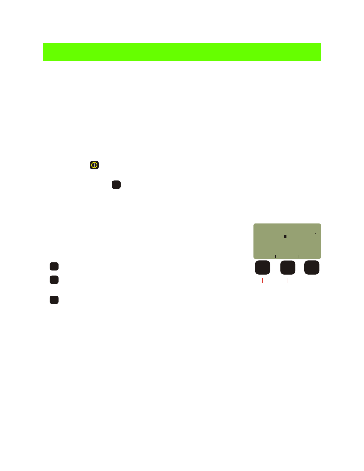
22) Disconnect the patch cord from the FiberMeter. NOTE: remember to keep the patch cord
connected to the light source for the duration of the test.
23) Connect the meter and light source to opposite ends of the link under
test. The display should appear similar to the figure at the right.
24) Once a readings appears, press to store the reading.
F2F2
25) If this is the first data point stored for this link, a prompt will appear for
entering a more descriptive fiber name. Press to continue.
DONE
452
PASS
FIBER
FBR:123
_____________________
UNITS
CERTIFICATION METER
BY 1 22X X
LINK #1
STORE
dB
82
68%
850nm
WAVE
Immediate Mode
3-13
Page 35

UNIT 3
CERTIFICATION METER
CERTIFICATION METER - Cabling Standard Certification Test; cont.
ACME
26) A review screen will appear with three options:
ABORT - do NOT save the data point, and return to Immediate
F1F1
Mode to re-test the same data point. If a FAIL reading appears, it
is recommended to ABORT, clean all connections, and then retest.
RENAME - change the descriptive fiber name (same as step 27).
F2F2
F3F3
SAVE - save the data point, and advance to the next data point in Immediate Mode. Notice
that the fiber number automatically increments to the next number.
27) Once the data has been stored for the current fiber, move the units to the next fiber, and repeat steps
24 through 26 until all fibers have been tested.
Once all data is stored in the FiberMeter, they can be downloaded to a PC which has Extech Reporter
installed. Please consult the Extech Reporter unit for more information.
CORP.
NAME
TYPE
-2 45X
_____________________
ABORT
FBR:1
62 5um
MM
PASS
dB
1850nm
RENAME SAVE
Data Point Review
NOTE: the memory in the FiberMeter allows for permanent storage of data, including reference and power
readings. Data will remain in the meter, even when the unit is powered off, until it is removed by the user.
3-14
Page 36

UNIT 3
CERTIFICATION METER
CERTIFICATION METER - Creating User-Definable Cabling Standards
Some companies have their own set of optical fiber loss parameters – such as fiber loss, connector loss and
splice loss – that they need their network to adhere to. Thus, the FiberMeter allows the user to configure two
user-definable cabling standards for the purpose of fiber certification.
These standards are defined when selecting the fiber standard during the Link Wizard process.
NOTE: one of the key parameters for defining these custom cabling standards is fiber loss (dB per kilometer).
Each custom standard supports a different range of optical losses (for up to 2 wavelengths), thus it is important
to know what the fiber loss is because this determines which user-definable standard to use.
USER DEFINED #1 supports fiber losses for up to two wavelengths from 0.01 dB to 2.55 dB per kilometer
USER DEFINED #2 supports fiber losses for up to two wavelengths from 0.1 dB to 25.5 dB per kilometer
1) Press to scroll through the list of fiber standards.
2) When the correct custom standard is highlighted, press to EDIT.
3) From the SELECT WAVELENGTHS screen, press to scroll to the
F1F1
F3F3
F1F1
first wavelength to configure.
4) Press to select this wavelength as the first wavelength.
F2F2
5) Enter the loss per kilometer in dB for 62.5/125 MM fiber in the entry field.
Decimals can be entered by holding the key to scroll through the
0
. - /
special characters. If it is not necessary to enter a value, leave the entry
field blank.
6) Press to continue. Repeat Steps 5 & 6 for the remaining fiber types.
7) Enter the loss per connection in dB, then press to continue.
8) Enter the loss per splice in dB, then press to continue.
9) Highlight the other wavelength to use for this standard and press to
DONE
DONE
DONE
F3F3
select.
10) Repeat steps 5 through 8 for the second wavelength. Press to return
to the fiber standard selection screen, then press to select the custom standard.
F2F2
DONE
3-15
FIBER
USER DEFINED #1
USER DEFINED #2
TIA-568B
ISO/IEC 11801
_____________________
NEXT
SELECT WAVELENGTHS(2)
_____________________
NEXT
850nm 62 5um MM0 0 0
loss/km(0 01-2 55dB):0 0
[ ]010000
_____________________
<--- --->
Enter Loss/Connector
(dB):
[ ]010000
_____________________
<--- --->
Enter Loss/Splice
(dB):
[ ]010000
_____________________
<--- --->
*1
*2
850nm
980nm
1300nm
1310nm
STANDARDS
3/CAN-T529
SELECT
SEL1 SEL2
SHIFT
SHIFT
SHIFT
EDIT
Page 37

UNIT 4
Extech Reporter
Overview
Extech fiber optic certification meters are designed to certify fiber optic links using cabling standards because
we understand the importance of qualifying your fiber installations with standards-compliant test equipment.
Extech Reporter software comes FREE with Extech certification meters, and is used to print professionally
formatted reports showing the conformity to these popular industry standards. You can print out these reports
as a record of the original conformity to quality set by the standards. These documents signed by all
associated parties may prove valuable in any future disputes concerning the installation.
Each Extech certification meter comes with a CD-ROM containing Extech Reporter software and a RS-232
download cable. Extech Reporter requires a PC with a Pentium or better processor and Windows 95 or later,
as well as a RS-232 serial port. PCs that only have USB ports can use a USB-to-serial converter.
Installing Extech Reporter
Use the following steps to install Extech Reporter onto a PC.
1) Insert the Extech CD-ROM into the PC. You may be prompted to choose your language.
2) Click the “Install Extech Reporter” button from the installation selection panel.
3) Click “Next” on the Setup Wizard greeting screen.
4) Choose the components to install, then click “Next” on the Choose Component screen.
5) Click “Next” on the Choose Install Location screen.
6) Click “Next” on the Choose Start Menu Folder screen.
7) Select the appropriate software option for your meter and click “Next” on the Choose Software
Version screen to begin copying files to the hard drive.
Once the files have completed copying you will be prompted to reboot your PC to complete the installation.
Using Extech Reporter
Below is a screenshot of the opening screen. When Extech Reporter is opened, the data area will be empty,
and the status bar will show a status of “Ready”.
Menu Bar
Tool Bar
Data Area
Status Bar
4-1
Page 38

UNIT 4
Extech Reporter
Downloading Data into Extech Reporter
Once testing is complete, data should be downloaded to the PC for report printing and data storage. The
following steps demonstrate how to download data from the FiberMeter.
1) Power on the FiberMeter meter, and select CERTIFICATION METER.
2) Connect the meter to the PC serial port via the supplied download cable.
3) Launch Extech Reporter.
4) Either click the Download menu option, or press the button from the Tool Bar.
All stored readings will be downloaded into Extech Reporter.
Viewing Extech Reporter Data - Summary View
Once data has been downloaded, they
appear in the data area of Extech
Reporter in an easy-to-read summary
format, called Summary View.
The top section contains information
about the meter, including company
name and telephone, meter type, serial
number, and firmware version.
The bottom section (called Circuit
Results Summary) shows a summary of
data points. This information includes
fiber link name, fiber name and number,
and a PASS or FAIL rating. Different
wav e l e ngths will h ave separa t e
columns.
Wavelength information can be toggled
between PASS/FAIL and overhead in dB
by using the tool bar button .
Overhead will be either positive (PASS)
or negative (FAIL).
Use the navigation buttons on the tool
bar (the green arrows) to advance forward or backward in the data, either one at a time, 10 at a time, or to the
beginning or end of the data. Data points may also be deleted by using either the delete button or the delete
option under the Edit menu.
4-2
Page 39

UNIT 4
Viewing Extech Reporter Data - Detail View
Data can also be viewed in more detail for
each fiber name and number. This view is
called Detail View.
Use the button to toggle between
Summary View and Detail View.
The top section contains information about
the meter, including company name and
telephone, meter type, serial number, and
firmware version.
The next section contains information such
as Link ID, Circuit ID, date of meter
calibration, date of test, temperature, and
date of download. NOTE: if the Date of Test
has an incorrect date, and you have not
deleted the data, you can fix this by editing
the link date in the Configure Link option
from the FIBER LINK MENU.
Extech Reporter
The Circuit Characteristics section shows
the information that was entered during the
Link Wizard, and used to calculate the
optical reference.
The Circuit Test Results section shows
detailed information about the specific data
point for each wavelength.
System Reference Power is the optical
power level that determines if a link will
pass or fail the certification test. All data
points with the link are measured against
this number. If the Measured Power is higher than the System Reference Power, the fiber passes. Likewise,
if it is lower, it fails.
NOTE: fibers with marginal System Overhead values (0.5 dB or less) may indicate a fail rating and should be
re-examined and re-tested. Clean all fiber connections and examine all connector endfaces for dirt or
cracks. Replace patch cords or re-terminate fiber connectors, if necessary, then re-test the fiber link.
If the link continues to be marginal, further troubleshooting will be necessary.
4-3
Page 40

UNIT 4
Printing Reports from Extech Reporter
Reports can be printed from
Extech Reporter by using
the print function, either
from the File Menu or the
Print button on the Tool Bar.
The c u r rent view w i l l
determine which report will
be printed, (i.e. if data is
being viewed in Summary
View, a Circuit Summary
report, like the one at right,
will be printed).
Reports will look nearly the
same as the views they
were printed from.
Extech Reporter
Areas for signatures and
dates are included at the
bottom of the reports.
NOTE: if you are interested in creating a PDF file of your printouts, there is a shareware program called
PDF995 that installs a PDF printer onto your system. Print the file as normal, and save the PDF file to the
folder of your choice. See http://pdf995.com for more information.
4-4
Page 41

UNIT 4
Extech Reporter
Saving and Retrieving Data in Extech Reporter
It is recommended to save Extech Reporter data to disk after downloading for backup and later retrieval. The
save function can be activated from the File Menu or the Tool Bar.
Extech Reporter data files can be re-opened by using the File Menu or Tool Bar.
NOTE: if data downloaded from the FiberMeter needs to be separated into multiple files, it is recommended to
save the original file as a master. This master file is then used to create individual files by deleting the
unneeded data.
Help Menu
The Help Menu contains Extech Reporter software version information, as well as links to several operations
manuals.
Interpreting Extech Reporter Screens and Reports
The following list of terms appear on the Extech Reporter software screen and/or printed report.
– Connector Loss
– Fiber Loss
– Light Source Reference Power
– Measured Power
– Operating Margin (%)
– Optical Loss
– Pass/Fail
– Splice Loss
– System Overhead
– System Reference Power
– Total Allowable System Loss
Descriptions for each of these terms are listed on the following pages.
4-5
Page 42

UNIT 4
Extech Reporter
Connector Loss
Definition: during the calculation of an optical loss budget, the amount of optical loss attributed to
interconnections in the link under test. An interconnection is the junction between two fiber connectors;
e.g. a patch panel or fiber opticadapter. Connector loss is specified by cabling standards that base link
budget calculation on the passive components of the link under test; examples of this type of standard are
the TIA-568 and the ISO IEC 11801.
Units: dB per connection
Calculation: (Number of interconnections) x (dB loss per connection)
Link Under Test
Patch
Panel
Patch
Cable
(to active
equipment)
Interconnection
Link
Under
Test
Patch
Panel
Fiber Loss
Definition: during the calculation of an optical loss budget, the amount of optical loss attributed to the
optical fiber in the link under test. Fiber loss is specified by cabling standards that base link budget
calculation on the passive components of the link under test; examples of this type of standard are the
TIA-568 and the ISO IEC 11801.
Units: dB per kilometer; loss values are different for different wavelengths and different fiber types
Calculation: (fiber length in kilometers) x (dB loss per kilometer)
Link Under Test
Patch
Panel
Patch
Panel
4-6
Page 43

UNIT 4
Extech Reporter
Interpreting Extech Reporter Screens and Reports, cont.
Light Source Reference Power
Definition: the amount of absolute optical power being received directly from the light source by the
power meter during the setting of the optical reference. Light Source Reference Power is used as a
reference, or starting point, on which a standards-based optical reference is set.
Units: dBm
Calculation: none; Light Source Reference Power is measured via a single patch cord of the appropriate
type.
CHARGER
850nm 1300nm
DualDual
LEDLED
MULTI MODE
LIGHT SOURCE
Total Allowable System Loss
Optical Loss
NOTE: testing standards require multimode reference
cables to be wrapped around a device called a mandrel,
which is used to filter high-order modes and achieve EMD,
or Equilibrium Mode Distribution (shown here).
Singlemode test jumpers do NOT require this mandrel.
INVALID
OPERATING
MARGIN **
Reference
Power (dBm)
Light
Source
PASS
OPERATING MARGIN
SYSTEM OVERHEAD
Measured
Power (dBm)
or
Minimum
Required
Power (dBm)
FAIL
4-7
Page 44

UNIT 4
Extech Reporter
Interpreting Extech Reporter Screens and Reports, cont.
Measured Power
Definition: the amount of absolute optical power being received from the light source by the power meter
after theyhave been connected to the link under test. Measured Power is compared to the System
Reference Power forPass/Fail analysis; if Measured Power is greater than the System Reference Power,
the link passes; likewise if Measured Power is less than the System Reference Power, the link fails.
Units: dBm
Calculation: none
Link Under Test
Patch
Panel
Patch
Panel
CHARGER
850nm 1300nm
DualDual
LEDLED
MULTI MODE
LIGHT SOURCE
INVALID
OPERATING
MARGIN **
Power (dBm)
Light
Source
Reference
Total Allowable System Loss
Optical Loss
PASS
Measured
Power (dBm)
OPERATING MARGIN
or
SYSTEM OVERHEAD
Power (dBm)
Minimum
Required
FAIL
Operating Margin %
(only appears on printed circuit detail reports)
Definition: the difference between the Measured Power and the System Reference Power, also known
as headroom, expressed as a percentage.
Units: percentage (%)
Calculation: none
INVALID
OPERATING
MARGIN **
Total Allowable System Loss
Optical Loss
PASS
OPERATING MARGIN
or
SYSTEM OVERHEAD
FAIL
4-8
Light
Source
Reference
Power (dBm)
Measured
Power (dBm)
Minimum
Required
Power (dBm)
Page 45

UNIT 4
Extech Reporter
Interpreting Extech Reporter Screens and Reports, cont.
Optical Loss
Definition: the amount of optical power that is lost through the link under test due to the attenuation of the
passive components of the link (i.e. optical fiber, interconnections, and splices).
Units: dB
Calculation: (Light Source Reference Power) - (Measured Power)
Total Allowable System Loss
Optical Loss
INVALID
OPERATING
MARGIN **
Reference
Power (dBm)
Light
Source
PASS
OPERATING MARGIN
SYSTEM OVERHEAD
Measured
Power (dBm)
or
Minimum
Required
Power (dBm)
FAIL
Pass/Fail
Definition: the rating a link receives when its Measured Power is compared to its System Reference
Power, based upon the attenuation parameters or loss values specified by cabling standards. A link
passes when Measured Power is greater than the System Reference Power. A link fails when Measured
Power is less than the System Reference Power.
Total Allowable System Loss
Units: N/A
Calculation: N/A
** If the Measured Power is greater than the Light Source Reference Power, then the circuit will receive an Invalid Operating Margin error, indicating an invalid test condition. Circuit test results receiving this error
should be considered as a FAIL.
In other words, more light is received through the whole link from end to end than was received through the single reference patch cable. This is physically impossible since this would indicate GAIN in the system
rather than LOSS.
This condition usually occurs when the reference was set up incorrectly. The correct sequence of steps to set a reference follow:
1) MULTIMODE ONLY - wrap the reference cable seven (7) times around a 0.7” mandrel (0.7” for 62.5um, and 0.9” for 50um) and secure.
2) Connect the ends of the reference cable to the power meter detector port and the appropriate light source port.
3) Power ON and set the units to the same wavelength.
4) Set the reference (or “ZERO”) in the power meter using the procedure in the operations guide.
The most important part of certification testing is to ensure that the integrity of the reference (or “ZERO”) is maintained.
Two factors to keep in mind are:
– Do NOT remove the patch cord from the light source port until all tests have been completed
– MULTIMODE ONLY - do NOT allow the patch cord to unwrap from the mandrel
INVALID
OPERATING
MARGIN **
Power (dBm)
Light
Source
Reference
Optical Loss
PASS
OPERATING MARGIN
SYSTEM OVERHEAD
Measured
Power (dBm)
or
Minimum
Required
Power (dBm)
FAIL
4-9
Page 46

UNIT 4
Interpreting Extech Reporter Screens and Reports, cont.
Extech Reporter
Splice Loss
Definition: during the calculation of an optical loss budget, the amount of optical loss attributed to splices
in the link under test. Splice loss is specified by cabling standards that base link budget calculation on the
passive components of the link under test; examples of this type of standard are the TIA-568 and the ISO
IEC 11801. Splices can be either mechanical or fusion, and can be located anywhere along the link under
test.
Units: dB per splice
Calculation: (number of splices) x (dB loss per splice)
Link Under Test
Patch
Panel
Splice
Patch
Panel
NOTE: some connectors use mechanical
splice technology for fiber termination,
such as the Unicam -compatible. These
connectors should be considered splices
when calculating optical loss budgets.
®
System Overhead
Definition: the difference between the Measured Power and the Minimum Required Power. System
Overhead is also known as headroom. With a PASS rating, System Overhead shows how much
additional loss a link can bear before it will fail. With a FAIL rating, System Overhead shows how much
optical loss must be overcome before it will pass.
Units: dB
Calculation: (Measured Power) - (Minimum Required Power)
Total Allowable System Loss
Optical Loss
INVALID
OPERATING
MARGIN **
PASS
OPERATING MARGIN
or
SYSTEM OVERHEAD
FAIL
4-10
Light
Source
Reference
Power (dBm)
Measured
Power (dBm)
Minimum
Required
Power (dBm)
Page 47

UNIT 4
Extech Reporter
Interpreting Extech Reporter Screens and Reports, cont.
(shown as Minimum Required Power on Circuit Detail Reports)
System Reference Power
Definition: the optical power level that determines whether a link passes or fails; a.k.a. Pass/Fail
threshold. If the Measured Power is greater than the System Reference Power, the link will show PASS;
likewise, if the Measured Power is less than the System Reference Power, the link will show FAIL.
NOTE: link measurements that are marginal (meaning that they are close to the System Reference
Power, within the accuracy of the test equipment) should be evaluated further.
Units: dBm
Calculation: (Light Source Reference Power) + (Total Allowable System Loss)
Total Allowable System Loss
Optical Loss
INVALID
OPERATING
MARGIN **
Power (dBm)
Light
Source
Reference
PASS
OPERATING MARGIN
SYSTEM OVERHEAD
Measured
Power (dBm)
or
Minimum
Required
Power (dBm)
FAIL
Total Allowable System Loss
Definition: the total amount of optical loss attributed to the passive components of the link (i.e. Fiber
Loss, Connection Loss, and Splice Loss). Total Allowable System Loss is also known as a Link Budget.
For generic cabling standards such as the TIA 568 or the ISO/IEC 11801, link budgets are calculated
based upon the actual configuration of the link under test. Some standards (e.g. various Ethernets) have
pre-defined link budget loss values based upon the upper limits of the link configuration.
Units: dB
Calculation: (Fiber Loss) + (Connection Loss) + (Splice Loss)
Total Allowable System Loss
Optical Loss
INVALID
OPERATING
MARGIN **
Power (dBm)
Light
Source
Reference
PASS
OPERATING MARGIN
SYSTEM OVERHEAD
Measured
Power (dBm)
or
Minimum
Required
Power (dBm)
FAIL
4-11
Page 48

UNIT 5
Appendices
Glossary
Absorption. The loss of power in an optical fiber, resulting from conversion of optical power into heat and
caused principally by impurities, such as transition metals and hydroxyl ions, and also by exposure to nuclear
radiation.
Acceptance Angle. The half-angle of the cone within which incident light is totally internally reflected by the
fiber core. It is equal to arcsin (NA).
Application Cabling Standard. A cabling standard that has been developed for a specific network protocol,
such as Ethernet. These standards use pre-defined link budgets for optical loss measurements.
Attenuation. A general term indicating a decrease in power from one point to another. In optical fibers, it is
measured in decibels per kilometer at a specified wavelength.
Bandwidth. The transmission capacity of a system.
Buffering. 1. A protective material extruded directly on the fiber coating to protect the fiber from the
environment (tight buffering). 2. Extruding a tube around the coated fiber to allow isolation of the fiber from
stresses on the cable (loose buffered)
Buffer Tubes. Loose-fitting covering over optical fibers used for protection and isolation.
Bundle. Many individual fibers contained within a single jacket or buffer tube. Also, a group of buffered fibers
distinguished in some fashion from another group in the same cable core.
Cladding. The outer concentric layer that surrounds the fiber core and has a lower index of refraction.
Connector. A mechanical device used to provide a means for aligning, attaching, and achieving continuity
between fibers.
Consolidation Point. A location for interconnection between horizontal cables that extend from building
pathways and horizontal cables that extend into work area pathways.
Core. The central, light-carrying part of an optical fiber; it has an index of refraction higher than that of the
surrounding cladding.
Cross-Connection. A connection scheme between cabling runs, subsystems, and equipment using patch
cords or jumpers that attach to connecting hardware on each end.
Decibel (dB). In fiber optics, a standard logarithmic unit for the ratio of the power that was received over the
power that was originally sent.
dBm. Decibel referenced to a milliwatt.
dBµ. Decibel referenced to a microwatt.
5-1
Page 49

UNIT 5
Appendices
Glossary, cont.
Detector. An optoelectronic transducer used in fiber optics for converting optical power to electric current. In
fiber optics, usually a photodiode.
Diffraction. The bending of radio, sound, or light waves around an object, barrier, or aperture edge.
Dispersion. A general term for those phenomena that cause a broadening or spreading of light as it
propagates through and optical fiber. the three types are modal, material, and waveguide.
Entrance Facility. An entrance to a building for both public and private network service cables including the
entrance point at the building wall and continuing to the entrance room or space.
Equilibrium Mode Distribution (EMD). The steady modal state of a multimode fiber in which the relative power
distribution among modes is independent of fiber length.
Equipment Room. A centralized space for telecommunications equipment that serves the occupants of the
building. Equipment housed herein is considered distinct from a telecommunications closet because of its
nature or complexity of the equipment.
Frequency. Of a periodic wave, the number of identical cycles per second. Usually expressed in Hertz.
Fresnel Reflection. The reflection that occurs at the planar junction of two materials having different refractive
indices; Fresnel reflection is not a function of the angle of incidence.
Graded-index Fiber. An optical fiber whose core has a nonuniform index of refraction. The core is composed
of concentric rings of glass whose refractive indices decrease from the center axis. The purpose is to reduce
modal dispersion and thereby increase fiber bandwidth.
Generic Cabling Standard. A cabling standard that calculates link budgets based on the passive component
configuration of the network, and is protocol-independent. Examples are TIA/EIA-568 and ISO 11801.
Horizontal Cross-Connect (HC). A cross-connect of horizontal cabling to other cabling, e.g., horizontal,
backbone, equipment.
Index of Refraction. The ration of the velocity of light in free space to the velocity of light in a given material.
Insertion Loss. The loss of power that results from inserting a component, such as a connector or splice, into
a previously continuous path.
Interconnection. A connection scheme that provides for the direct connection of a cable to another cable or to
an equipment cable without a patch cord or jumper.
Intermediate Cross-Connect (IC). A cross-connect between the main cross-connect and the horizontal
cross-connect in backbone cabling.
Laser. Light Amplification by Stimulated Emission of Radiation. A light source producing, through stimulated
emission, coherent, near monochromatic light. Lasers in fiber optics are usually solid-state semiconductor
types.
5-2
Page 50

UNIT 5
Appendices
Glossary, cont.
Light-Emitting Diode (LED). A semiconductor diode that spontaneously emits light from the PN junction when
forward current is applied.
Main Cross-Connect (MC). The cross-connect in the main equipment room for connecting entrance cables,
backbone cables, and equipment cables.
Material Dispersion. Dispersion resulting from the different velocities of each wavelength in an optical fiber.
Modal Dispersion. Dispersion resulting from the different transit lengths of different propagating modes in a
multimode optical fiber.
Mode. A possible path followed by light rays.
Multimode Fiber. A type of optical fiber that supports more than one propagating mode.
Numeric Aperture (NA). The number that expresses the light-gathering ability of a fiber.
Optical Time Domain Reflectometry (OTDR). A method of evaluating optical fibers based on detecting
backscattered (reflected) light. Used to measure fiber attenuation, evaluate splice and connector joints, and
locate faults. Also, the equipment used to perform such measurements (Optical Time Domain
Reflectometer).
Photodetector. An optoelectronic transducer, such as a PIN photodiode or avalanche photodiode.
Photodiode. A semiconductor diode that produces current in response to incident optical power and used as
a detector in fiber optics.
Photon. A quantum of electromagnetic energy; a particle of light.
Receiver. An electronic device which converts optical signals to electrical signals.
Responsivity. The ratio of a photodetector’s electrical output to its optical input in an optical fiber.
Singlemode Fiber. An optical fiber that supports only one mode of light propagation above the cutoff
wavelength.
Source. The light emitter, either an LED or laser diode, in a fiber optic link.
Spectral Width. A measure of the extent of a spectrum. For a source, the width of wavelengths contained in
the output at one half of the wavelength of peak power. Typical spectral widths are 20 to 60 nm for an LED and
2 to 5 nm for a laser diode.
Splice. An interconnection method for joining the ends of two optical fibers in a permanent or semipermanent fashion.
Step-Index Fiber. An optical fiber, either multimode or single mode, in which the core refractive index is
uniform throughout so that a sharp step in refractive index occurs at the core-to-cladding interface. It usually
refers to a multimode fiber.
5-3
Page 51

UNIT 5
Appendices
Glossary, cont.
Telecommunications Closet (TC). An enclosed space for housing telecommunications equipment, cable
terminations, and cross-connects. The closet is the recognized cross-connect between the backbone cable
and horizontal cabling.
Tight Buffer. A cable construction where each fiber is tightly buffered by a protective thermoplastic coating to
a diameter of 900 uM.
Transmitter. An electronic package which converts an electrical signal to an optical signal.
Wavelength. The distance between the same two points on adjacent waves; the time required for a wave to
complete a single cycle.
Work Area. A building space where the occupants interact with telecommunications terminal equipment; i.e.
PCs, telephones, and other office equipment.
FiberMeter Specifications
Detector Type
NIST-Traceable Wavelengths
Measurement Range
Accuracy
Resolution
Battery Life
Connector Type
Operating Temperature
Storage Temperature
Size
Weight
Data Storage Points
Download Data Points
Absolute/Relative Measurements
Battery Capacity Display
Backlight
NIST Traceable
InGaAs
850, 1300, 1310, 1550
980, 1490, 1625
+5 to -70 dBm (FO600; FO602)
+25 to -50 dBm (FO610)
+0.15 dB
0.01 dB
up to 100 hours (9V)
Universal w/2.5 and 1.25mm cap
-10 to 55 C
-30 to 70 C
3.48”W x 6.48”H x 1.1”D
373g (12 oz.)
up to 1000
Extech Reporter Software
Yes
Yes
Yes
Yes
5-4
Page 52

UNIT 5
Appendices
Cleaning and Care Instructions
1 - Do NOT drop any piece of sensitive scientific equipment. Damage may occur to the case or electronic
components on the circuit board may become dislodged, and inaccuracy may occur.
2 - Keep the meter in an enclosed case when not in use. This will help protect the meter from the elements
and accidental droppage.
3 - Store the meter in a cool dry area when not in use in order to keep the meter in top working condition.
4 - We recommend not removing the universal connector as it is not necessary for cleaning. Its parts are very
fragile, small, and easy to lose.
5 - Always remember to replace the rubber cap on the connector. This will keep out dust and dirt when the
meter is not in use.
6 - Use only 99% or better Isopropyl alcohol when cleaning the detector. Any less than 99% contains too
much water and will begin to corrode the components. 99% Isopropyl alcohol is very flammable, so additional
care must be taken when cleaning the detector. 99% Isopropyl alcohol can be purchased at your local drug
store.
7 - Whenever possible, use specially designed 2.5mm cleaning sticks to clean the detector. These do not
require alcohol and do not damage the insides of the connector. Do not used sticks or swabs of any other type
because they may damage the zirconium ferrule or the coating of the detector inside the connector, or may
leave behind dust or fibers that will add loss to the fiber reading.
8 - The detector port should be cleaned at the beginning and end of each testing day to keep connector loss
during testing at a minimum.
9 - When cleaning the meter itself, do not use any household cleaner that contains ammonia as this will
damage any plastic it comes in contact with.
10 - The case is splash-proof, so it is not necessary to clean the inside of the meter.
11 - Only use lint-free cloths when cleaning the display. Anything else may scratch the plastic.
5-5
Page 53

UNIT 5
Appendices
Warranty Information
Warranty
EXTECH INSTRUMENTS CORPORATION warrants this instrument to be free of defects in parts and
workmanship for one year from date of shipment (a six month limited warranty applies on sensors and
cables). If it should become necessary to return the instrument for service during or beyond the warranty
period, contact the Customer Service Department at (781) 890-7440 ext. 210 for authorization or visit our
website at www.extech.com (click on 'Contact Extech' and go to 'Service Department' to request an RA
number). A Return Authorization (RA) number must be issued before any product is returned to Extech. The
sender is responsible for shipping charges, freight, insurance and proper packaging to prevent damage in
transit. This warranty does not apply to defects resulting from action of the user such as misuse, improper
wiring, operation outside of specification, improper maintenance or repair, or unauthorized modification.
Extech specifically disclaims any implied warranties or merchantability or fitness for a specific purpose and
will not be liable for any direct, indirect, incidental or consequential damages. Extech's total liability is limited
to repair or replacement of the product. The warranty set forth above is inclusive and no other warranty,
whether written or oral, is expressed or implied.
Calibration and Repair Services
Extech offers complete repair and calibration services for all of the products we sell. For periodic calibration,
NIST certification on most products or repair of any Extech product, call customer service for details on
services available. Extech recommends that calibration be performed on an annual basis to ensure
calibration integrity.
All rights reserved including the right of reproduction in whole or in part in any form.
Copyright © 2002 Extech Instruments Corporation.
5-6
Page 54

UNIT 5
Appendices
Supported Cabling Standards
This version of FiberMeter firmware supports the following fiber optic network cabling standards, and also
supports 2 user-definable standards.
ITU G.983.3
EIA/TIA-568
CAN-T529
ISO/IEC 11801
10 Gigabit Ethernet
1000Base-SX
1000Base-LX
100Base-FX
10Base-FL
10Base-FB
FDDI
ATM-155
ATM-622
Fibre Channel
Token Ring
5-7
Page 55

UNIT 5
Appendices
Reference Cable Setup
Your test jumpers must be cleaned and inspected prior to using them for fiber link testing. You should have
one jumper for the power meter side of the test, and one jumper for each of the connector ports on your light
source. Make sure that these patch cords match the fiber under test (i.e. same fiber type, same core/cladding
size, same connector type).
Use the following steps to set up your reference jumpers for link testing:
1 - Connect the first jumper to the power meter and light source. Verify that it is working properly and not
introducing significant loss to the test. Disconnect this patch cord from the light source and meter and set it
aside.
2 - Connect the other patch cord(s) to the light source. If you have a dual wavelength light source with two
connector ports, then it is recommended to connect one jumper to each port.
3 - MULTIMODE ONLY. If you are testing multimode fibers, you will need to wrap each of the jumpers
connected to the light source around a mandrel seven times. This is done to achieve Equilibrium Mode
Distribution (EMD), which eliminates unwanted optical energy that can cause inaccurate test results.
4 - Set the optical reference. See the appropriate unit for detailed instructions on setting each optical
reference method.
NOTE: Do NOT remove the patch cords from the light source until you have completed testing all of the fibers
in the link. Disconnecting the test jumper from the light source and re-connecting it will cause the optical
reference to be incorrect, thereby producing incorrect readings, and may cause a link to fail.
CHARGER
850nm 1300nm
DualDual
MULTI MODE
LIGHT SOURCE
Fiber Type) Mandrel Size
(3mm jacket)
62.5/125 0.7 inches
50/125 0.9 inches
CHARGER
1310nm 1550nm
DualDual
SINGLE MODE
LIGHT SOURCE
Multimode
Reference
Singlemode
Reference
5-8
Page 56

UNIT 5
Appendices
10 Gigabit Ethernet Standard
Support for the IEEE 802.3ae 10-Gigabit Ethernet standard has been added to the FiberMeter Link Wizard,
which means that users can now certify their 10GbE networks.
With this new standard, users are given the option of choosing from one of several versions of this standard,
based on the fiber type, wavelength, and 10GbE electronics used. Below is a summary of the various 10GbE
standards as they are defined in the FiberMeter.
In order to choose the correct standard in the FiberMeter Link Wizard, it is important to know the specifications
of the fiber under test, especially the fiber type and modal bandwidth.
If these specifications are unknown, contact the optical fiber manufacturer for more details.
IEEE Standard
Name
10GBASE-S
10GBASE-S
10GBASE-S
10GBASE-S
10GBASE-S
10GBASE-LX4
10GBASE-LX4
10GBASE-LX4
10GBASE-LX4
10GBASE-LX4
10GBASE-L
10GBASE-E
FiberMeter Link
Wizard Name
10GBASE-S
LEGACY
10GBASE-S
OM1/OM2
10GBASE-S
LEGACY
10GBASE-S
OM1/OM2
10GBASE-S
OM3
10GBASE-LX4
LEGACY
10GBASE-LX4
LEGACY
10GBASE-LX4
10GBASE-LX4
10GBASE-LX4
10GBASE-L/E
10GBASE-L/E
Fiber
Type
62.5/125
multimode
62.5/125
multimode
50/125
multimode
50/125
multimode
laser-optimized
50/125 multimode
62.5/125
multimode
50/125
multimode
50/125
multimode
50/125
multimode
singlemode
singlemode
singlemode
Modal
Bandwidth
160 MHz • km
200 MHz • km
400 MHz • km
500 MHz • km
2000 MHz • km
500 MHz • km
400 MHz • km
500 MHz • km
2000 MHz • km
NA
NA
NA
Wavelength
850nm
850nm
850nm
850nm
850nm
1300nm
1300nm
1300nm
1300nm
1310nm
1310nm
1550nm
Loss (dB)
2.6
2.5
2.2
2.3
2.6
2.5
2.0
2.0
2.0
6.3
6.2
11.4
Maximum
Distance (m)
26
33
66
82
300
300
240
300
300
5000
5000
5000
5-9
Page 57

UNIT 5
Link Budget Calculation Worksheet
Appendices
Operating Wavelength
Fiber Type
Calculate Maximum System Attenuation
Fiber Loss at Operating Wavelength (Distance x Fiber Loss)
Total Cable Distance
Individual Fiber Loss (at operating wavelength)
Total Fiber Loss
Connector Loss (Connector Loss x Connector Pairs)
Individual Connector Loss
Number of Connector Pairs
Total Connector Loss
Splice Loss (Splice Loss x Splices)
Individual Splice Loss
Number of Splices
Total Splice Loss
Other Components
Maximum System Attenuation
Calculate Link Loss Budget
Determine System Gain (Avg. Transmitter Power - Receiver Sensitivity)
Average. Transmitter Power
Receiver Sensitivity
System Gain
km
dB/km
dB
dB
dB
dB
dB
dB
dB
dBm
dBm @ 10 BER
-9
dB
Power Penalties (Operating Margin + Receiver Power Penalties + Repair Margin # Splices at 0.3dB each)
Operating Margin
Receiver Power Penalties
Repair Margin
Total Power Penalty
Determine Link Loss Budget (System Gain - Power Penalty)
System Gain
Total Power Penalty
Total Link Loss Budget
dB
dB
dB
dB
dB
dB
dB
Verify Performance
Verify Adequate Power (Total Link Loss Budget - Total System Attenuation)
Total Link Loss Budget
Maximum System Attenuation
System Performance Margin*
dB
dB
* System Performance Margin must be
greater than 0 dB in order for the
system to operate using the specified
dB
electronics.
 Loading...