

Page 1
User's Guide
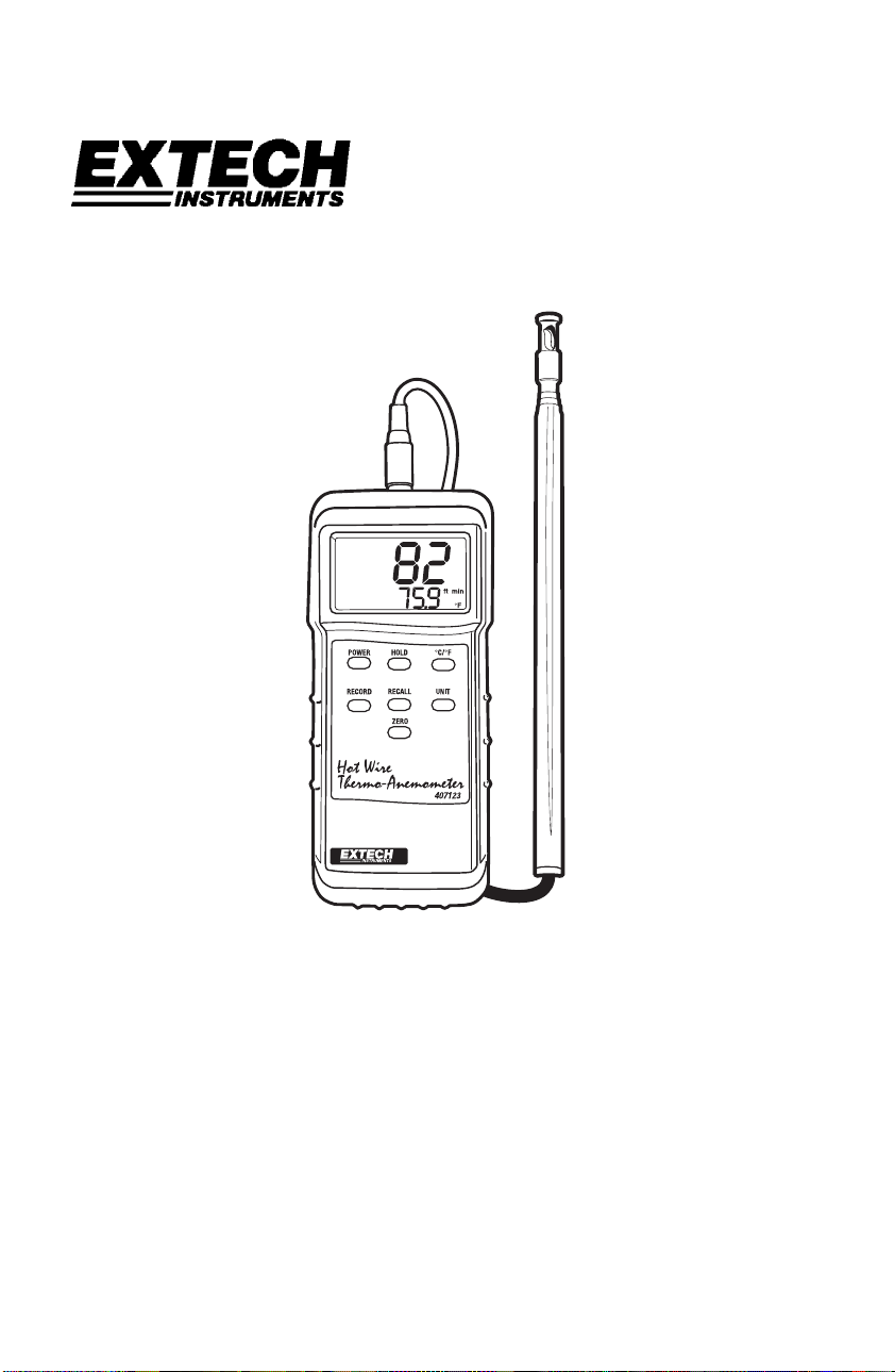
Hot Wire Thermo-Anemometer
Model 407123
Page 2
Introduction
Congratulations on your purchase of the Extech Hot Wire Anemometer. This instrument measures air
flow and temperature by placing the sensor into an airway such as a duct or a vent. The sensor is
situated at the end of the telescoping wand for convenience and has a protective sliding cover. The
meter includes an RS-232 PC Interface jack for use with the Model 407001 Data Acquisition software
and interface cable kit. This meter is shipped fully tested and calibrated and, with proper use, will provide
years of reliable service.
Specifications
General Specifications
Circuit configuration
Display 3-1/2 digit (2000 count) dual LCD display
Measurements m/s (meters per second), km/h (kilometers per hour), ft/min
Data hold Freezes reading on display
Sensor Structure Air velocity sensor: Glass bead thermistor
Min/Max Recording Record and Recall Maximum (MAX) and Minimum (MIN) readings
PC Interface RS 232 PC serial interface jack for use with Model 407001
Operating
Temperature
Operating Humidity Max. 80% RH
Power Supply Six (6) 1.5V ‘AAA’ batteries
Power Consumption Approx. 30 mADC
Weight 0.78 lb (355 g) including batteries & probe
Dimensions Main instrument: 7.1 x 2.8 x 1.3” (180 x 72 x 32 mm)
Range Specifications
Units
m/s 0.2 to 20.0 m/s 0.1 m/s ±(3.0%rdg+0.3m/s)*
km/h 0.7 to 72.0 km/h 0.1 km/h ±(3.0%rdg+1.1km/h)*
ft/min 40 to 3940 ft/min 1 ft/min ±(3.0%rdg+59ft/min)*
MPH 0.5 to 45.0 MPH 0.1 MPH ±(3.0%rdg+0.67MPH)*
knots 1.0 to 31.0 knots 0.1 knots ±(3.0%rdg+0.58knots)*
Temperature 32 to 122 oF (0 to
Note: m/s: meters per second; km/h: kilometers per hour; ft/min: feet per minute; Knots:
nautical miles per hour; MPH: miles per hour
Custom one-chip LSI microprocessor circuit
(feet/per minute), knots (nautical miles per hour),
hour), Temperature: °C, °F
Temperature sensor: Precision thermistor
software and interface cable kit
32 to 122°F (0 to 50 °C)
MPH (miles per
Sensor: 0.5” (12mm) diameter
Telescope: 7’ (2.1m) maximum length with cable
Range Resolution Accuracy
*or, ±(1.0%FS+3d) whichever is greater
50
o
C)
0.1 oF and oC 1.5 oF (0.8 oC)
2
Model 407123 V6.0 August 2007
Page 3
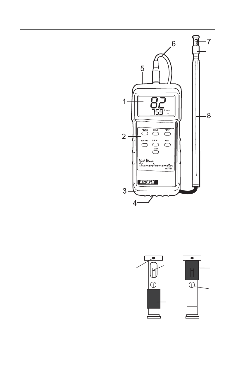
Description
Meter Description
1. LCD display – Indicates air velocity and
temperature readings, units of measure,
low battery icon, and other user alerts
2. Push-buttons:
• POWER: Turn meter ON and OFF
• HOLD: Freezes the displayed reading
• C/F: Select the temperature units
• RECORD: Press to track the highest
(MAX) and lowest (MIN) reading
• RECALL: Displays MAX/MIN readings
• UNIT: Air velocity units of measure
• ZERO: Press to zero the display
(sensor cover must be closed)
3. Protective holster – Rubber jacket that
surrounds the meter (must be removed
to access battery compartment)
4. Battery compartment - Located on the
lower back of the meter
5. PC Interface jack – Accepts a 3.5mm
plug from a PC interface cable (cable
and data acquisition software available
using part number 407001)
6. Sensor input jack – Insert the sensor
plug
7. Sensor opening – Air must flow through this opening for proper measurement
8. Telescoping sensor handle – Extends to 39” (1m)
9. Sensor protective cover – Slide DOWN to open when in use and slide UP to protect
sensor when not in use (close the cover when zeroing the meter)
Sensor Tip Description
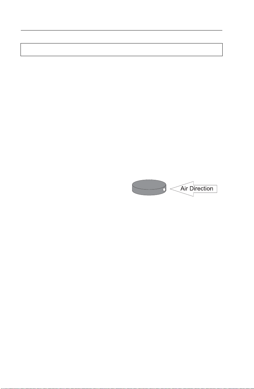
1. Air Direction indentation
2. Air Velocity Sensor
3. Sensor cover in lower (measurement) open position
4. Sensor cover in upper (zero) closed position
5. Temperature sensor
1
2
3
9
4
5
3
Model 407123 V6.0 August 2007
Page 4
Operation
Initialization and Zero
The meter should always be zeroed at temperature before use using the ZERO button.
Do not rely on the initial zero display.
Notes:
The meter does not display negative numbers.
Open antenna to desired length.
1. Connect the sensor to the input jack on top of the meter and open antenna to desired
length.
2. Turn on the meter using the Power button. The meter will perform a self-test during
which the display will count down from 9999 to 0000.
3. Select the desired temperature units using the C/F select button. The LCD will reflect
the selection.
4. Select the desired air velocity units using the UNIT button. The LCD will reflect the
selection.
5. Place the sensor cover in the UP (ZERO) position.
6. Place the sensor in the area to be measured and allow a short time for the sensor to
reach the temperature of the air under test.
7. Press the ZERO button to zero the meter.
Taking Measurements
1. Zero the meter as described above.
2. Slide the air velocity sensor cover down.
3. Place the sensor in the air current to be measured. Have the air flow meet the sensor
head in the direction of the indentation on the sensor head.
4. View the air velocity and temperature readings on the LCD Display. The large main
LCD display indicates the Air Velocity reading. The lower LCD sub-display indicates
the temperature reading.
4
Model 407123 V6.0 August 2007
Page 5

MIN and MAX Function
1. To begin capturing the Minimum (MIN) and Maximum (MAX) readings, press the
RECORD button. The ‘REC’ icon will appear on the LCD.
2. Take readings as described previously.
3. Press the RECALL button to view the Maximum reading encountered since the
RECORD button was pressed. The ‘MAX’ display icon will appear along with the
maximum reading.
4. Press RECALL again to view the minimum reading (MIN).
5. Press the RECORD button to exit this mode and return to normal operation.
Data Hold
To freeze the LCD display, press the HOLD button. The 'DH' display icon will appear on
the LCD. Press the HOLD button again to return to normal operation (the 'DH' hold icon will
switch off).
5
Model 407123 V6.0 August 2007
Page 6

Battery Replacement
When the low battery indicator (LBT) appears on the LCD or if the LCD does not switch on
when the POWER button is pressed, replace the batteries.
1. Remove the protective rubber holster that encapsulates the meter.
2. Open the rear battery compartment by prying the compartment off with a flat-head
screwdriver or a coin.
3. Replace the six ‘AAA’ 1.5V batteries observing polarity.
4. Replace the battery compartment cover and the protective holster.
PC Interface
The meter is equipped with an RS-232 PC Interface jack at the top of the meter (next to the
sensor input jack). This port is for use with the Extech Part Number 407001 Data
Acquisition software and interface cable kit. Directions for use are supplied with the
407001 kit. The interface kit allows the user to take measurements and view/save the
readings on a PC.
6
Model 407123 V6.0 August 2007
Page 7
Useful Equations and Conversions
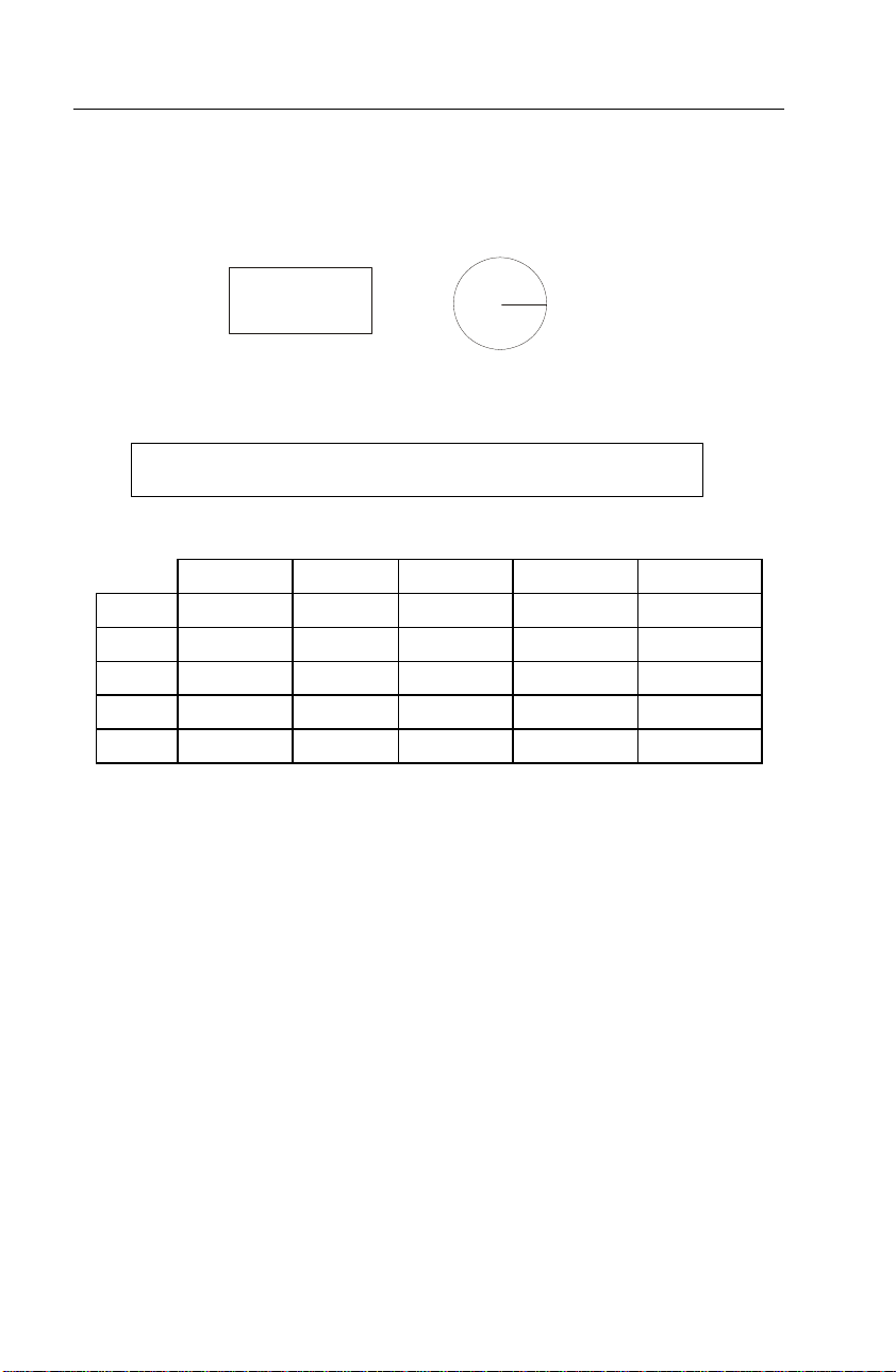
Area equations
The volume of air flowing through a duct or vent can be determined by taking the area of
the duct in square units (i.e. square feet) and multiplying this value by the measured
linear velocity (i.e., feet per minute). This gives: ft/min x ft
2
= ft3/min (CFM)
H
R
W
A = W x H
Cubic equations
CMM (m3/min) = Air Velocity (m/sec) x Area (m2) x 60
Units Conversion Table
m/s ft/min knots km/hr MPH
1 m/s 1 196.87 1.944 3.6 2.24
1 ft/min 0.00508 1 0.00987 0.01829 0.01138
1 knot 0.5144 101.27 1 1.8519 1.1523
1 km/hr 0.2778 54.69 0.54 1 0.6222
1 MPH 0.4464 87.89 0.8679 1.6071 1
3
/min) = Air Velocity (ft/min) x Area (ft2)
CFM (ft
A = pi x R
2
7
Model 407123 V6.0 August 2007
Page 8

Warranty
EXTECH INSTRUMENTS CORPORATION warrants this instrument to be free of defects
in parts and workmanship for one year from date of shipment (a six month limited warranty
applies to sensors and cables). If it should become necessary to return the instrument for
service during or beyond the warranty period, contact the Customer Service Department at
(781) 890-7440 ext. 210 for authorization or visit our website www.extech.com for contact
information. A Return Authorization (RA) number must be issued before any product is
returned to Extech. The sender is responsible for shipping charges, freight, insurance and
proper packaging to prevent damage in transit. This warranty does not apply to defects
resulting from action of the user such as misuse, improper wiring, operation outside of
specification, improper maintenance or repair, or unauthorized modification. Extech
specifically disclaims any implied warranties or merchantability or fitness for a specific
purpose and will not be liable for any direct, indirect, incidental or consequential damages.
Extech's total liability is limited to repair or replacement of the product. The warranty set
forth above is inclusive and no other warranty, whether written or oral, is expressed or
implied.
Calibration and Repair Services
Extech offers repair and calibration services for the products we sell. Extech also
provides NIST certification for most products. Call the Customer Care Department for
information on calibration services available for this product. Extech recommends that
annual calibrations be performed to verify meter performance and accuracy.
All rights reserved including the right of reproduction in whole or in part in any form.
Technical support: Extension 200; E-mail: support@extech.com
Product specifications subject to change without notice
For the latest version of this User’s Guide, Software updates, and other
up-to-the-minute product information, visit our website: www.extech.com
Extech Instruments Corporation, 285 Bear Hill Rd., Waltham, MA 02451
Copyright © 2007 Extech Instruments Corporation
Support line (781) 890-7440
Repair & Returns: Extension 210; E-mail: repair@extech.com
8
Model 407123 V6.0 August 2007
 Loading...