

Page 1

1
Congratulation on your purchasing this high performance 2-Port
RS232/422/485 3-in-1 Serial PCIe Host Adapter. The adapter is high speed PCIe
bus based and plug-and-play compliant. Its serial ports are fully 16C550 UART
compatible with most of the RS232, RS422 and RS485 devices available from
the market.
Features:
Fully PCI Express Specifications Revision 1.0a/1.1 Compliant
256-byte deep FIFO per transmitter and receiver
Supports 5V or 12V on its DB25 connector, provides an option to supply
power to all DB9 Connectors via the octopus cable
16C550 UARTs, Baud Rate up to 921.6Kbps
Supports 2 serial ports with RS232, RS422, RS485-2wire and RS485-4wire
modes (each port can be independently set) over one single PCIe slot
Automated in-band flow control using programmable Xon/Xoff in both
directions
Supports Windows 2000, XP, 2003, Vista, Win7, 8.x, 10 and Linux
EX-45362 & EX-45362IS
2S RS232/422/485 3-in-1 Serial PCIe Card
1. Introduction
2. Board Layout
JP1: Aux Power
Source Selector
J1: DB25 Male
External
Connector
S1_PWR:
Pin 9 Power
Selector for S1
S1_MODE:
MODE Switches
for S1
S2_PWR:
Pin 9 Power
Selector for S2
S2_MODE:
MODE Switches for S2
Page 2

2S RS232/422/485 3-in-1 Serial PCIe Card
2
1.
S1_PWR, S2_PWR: Pin-9 Power Setting Jumpers for S1, S2 Respectively: The
design of each DB9 male connector has an option to supply DC power
to its Pin-9. Pin number 9 of the DB9 connector was defined for RS232 RI
(Ring Indicator) signal. Since some applications do NOT use this signal, in
that case, Pin-9 can be used to deliver DC power for the serial devices.
This product provides 2 settings for the power, +5V and +12V. The default
factory setting was set at “RI”, i.e. no power supplied on the DB9M
connector’s pin-9.
Pin-9 Power Setting Table:
S1_PWR, S2_PWR
Jumper Settings
No Power Supplied on Pin-9
(Default)
+5V DC on Pin-9
+12V DC on Pin-9
3. Jumper and DIP Switch Settings
2-port fan out
octopus cable
Page 3

2S RS232/422/485 3-in-1 Serial PCIe Card
3
AUX. POWER Source Selector:
JP1
Settings
External 5V: Power source is +5VDC,
from J2 AUX power connector.
(Default)
External 12V: Power source is +12VDC,
from J2 AUX power connector.
Internal 12V: Power source is +12VDC,
from PCIe golden finger
(motherboard’s PCIe slot)
Internal 5V: Power source is +5VDC,
from onboard step-down regulator
2.
Mode DIP Switch Settings – S1_MODE, S2_MODE:
There are two 8-pin DIP switches S1_MODE and S2_MODE for the settings of
serial Port S1 and Port S2 respectively. It is used for changing the operating
modes, enable/disable terminator and enable/disable the bias for transmitter
and receiver signals.
Page 4

2S RS232/422/485 3-in-1 Serial PCIe Card
4
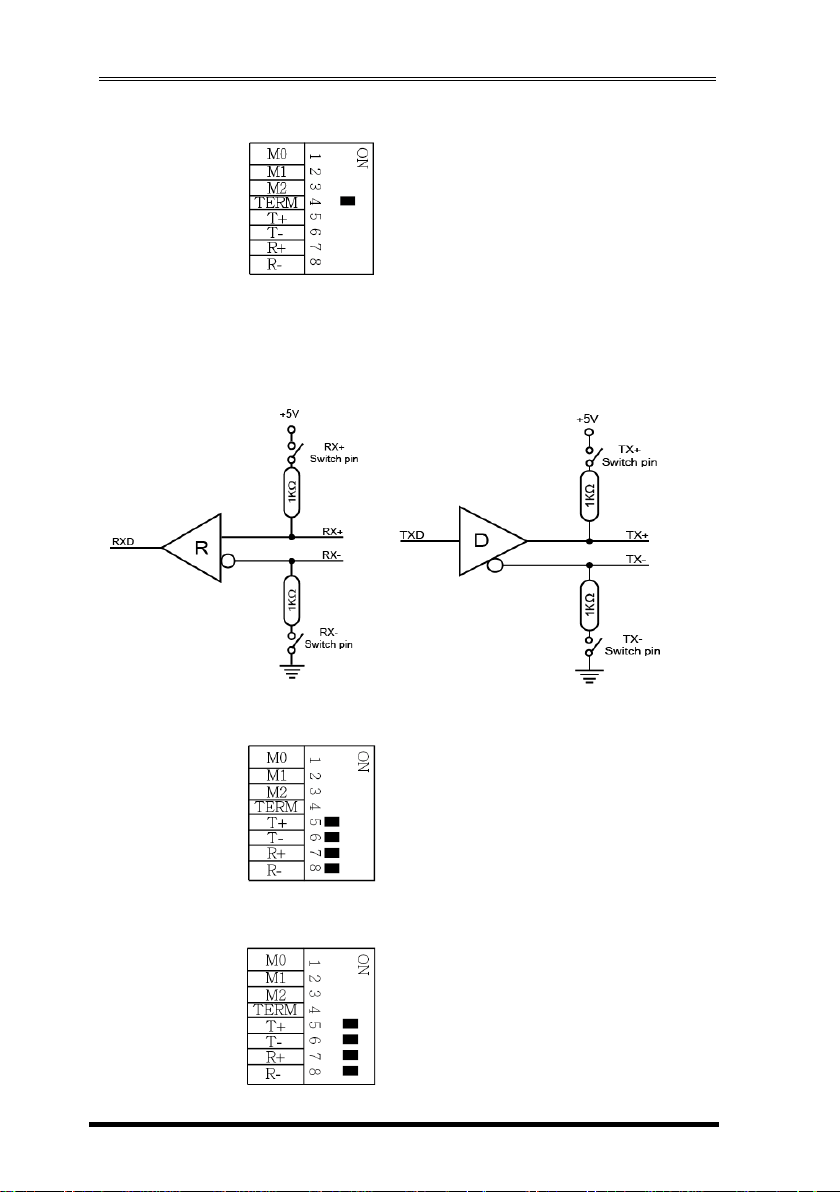
Mode Settings:
Each DIP switch has 8 pins, the first 3 pins (M0, M1, M2) are for mode settings
(RS232, RS485-2wire, RS485-4wire or RS422 modes), pin 4 (TERM) is to enable or
disable terminator. Pin 5 and 6 (T+, T-) is for biasing TX+ and TX- signals. Pin 7
and 8 (R+, R-) is to enable or disable bias for RX+ and RX- signals.
Note: Pin 4 to 8 are designed for RS422 and RS485 only and
should be set to OFF when you are setting the port to RS232 mode.
Modes
Settings
M0
M1
M2
(ON)
RS232
(Default)
RS485-2W
Page 5

2S RS232/422/485 3-in-1 Serial PCIe Card
5
RS485-4W
RS422
Termination Resistor Settings:
The pin 4 of the DIP switch is to enable the 120 Ohm termination resistor
between RX+ and RX- signals.
Terminator disabled (OFF, default):
DIP Switch Pin 4
DIP Switch Pin 4
RS485-2wire mode:
RS485-4wire or RS422 mode:
Page 6
2S RS232/422/485 3-in-1 Serial PCIe Card
6
Terminator enabled (ON):
Bias Resistors Enable/Disable:
Pin 5 to 8 of the DIP switch are to enable (ON) or disable (OFF) the 4 bias
resistors for TX+, TX-, RX+, RX- signals respectively. Please note that you have to
set them to OFF if you are setting the port to RS232 mode.
Disable (default) all 4 Bias resistors for TX+, TX-, RX+ and RX-:
Enable all 4 Bias resistors for TX+, TX-, RX+ and RX-:
DIP Switch Pin 5
DIP Switch Pin 6
DIP Switch Pin 7
DIP Switch Pin 8
Page 7
2S RS232/422/485 3-in-1 Serial PCIe Card
7
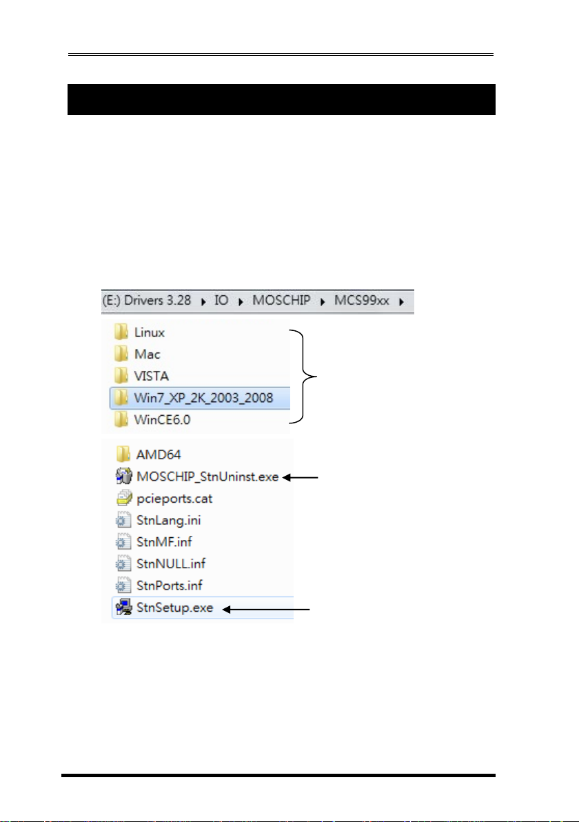
1. To install the Windows drivers, there are two methods, one is to
run the setup utility (StnSetup.exe) in each corresponding folder.
The other one is by the Windows’ driver installation Wizard. We
recommend you run the setup utility. It will be simpler. However,
PLEASE REFRESH HARDWARE OR REBOOT THE SYSTEM IN CASE
YOUR DRIVER DID NOT TAKE EFFECT AFTER RUNNING THE SETUP
UTILITY.
The drivers are shipped in the following folders on the driver CD:
E:\IO\MOSCHIP\MCS99xx
Drivers are in each
corresponding folder
4. Software Installation
Driver Uninstalling Program
Driver Installing Program
Page 8

2S RS232/422/485 3-in-1 Serial PCIe Card
8
In some cases, you may want to uninstall the drivers. To remove the
drivers that already installed for Windows, there are two methods:
1. Run (double click) the uninstall program (for example
MOSCHIP_StnUninst.exe) in each Windows’ folder on the
supplied driver CD, it is usually in the same folder as the
StnSetup.exe utility:
2. Go to Windows’ Control Panel’s Add/Remove Program to
remove the drivers.
The pin assignment of the DB9 male connector of the Module Box is
dependent on its operation modes. Please refer to the following
figure for the corresponding mode:
1. RS232 Pin Assignment:
RS232 DB9(Male) to DB9(Male) Wiring:
6. Connector Pin Assignments
DB9(RS232 PCIe Card) DB9(Serial Device)
1 DCD 1 DCD
2 RXD 2 RXD
3 TXD 3 TXD
4 DTR 4 DTR
5 GND 5 GND
6 DSR 6 DSR
7 RTS 7 RTS
8 CTS 8 CTS
5. Uninstalling the Software Drivers
Page 9

2S RS232/422/485 3-in-1 Serial PCIe Card
9
2. RS422 and RS485-4wire Pin Assignment:
RS422 Cable Wiring:
3. RS485-2wire Pin Assignment:
RS485-2wire Cable Wiring:
DB9 (RS422 PCIe Card)
1 TXD 2 TXD+
3 RXD+
4 RXD 5 GND
(RS422 Device)
1 TXD 2 TXD+
3 RXD+
4 RXD 5 GND
DB9 (RS485 PCIe Card)
1 DATA 2 DATA+
5 GND
(RS485 Device)
1 DATA 2 DATA+
5 GND
Page 10

2S RS232/422/485 3-in-1 Serial PCIe Card
10
Type
Specifications
Connectors
Cable
Bus Interface
Number of Ports
RS-232 Signals
RS422 Signals
RS485-4wire Signals
RS485-2wire
Baud Rate
Data Bits
Stop Bits
I/O address/IRQ
Parity
Flow Control
Power Requirement
Operating Temperature
Operating Humidity
Storage Temperature
DB25 Male
DB25F-to-DB9MX2 Octopus type
PCI Express x1
2
TXD, RXD, RTS, CTS, DTR, DSR, DCD, GND
TXD+, TXD-, RXD+, RXD-, GND
TXD+, TXD-, RXD+, RXD-, GND
DATA+(B)/DATA-(A)
110 bps to 921.6Kbps
5,6,7,8
1, 1.5, 2
Plug-and-Play (various)
None, Even, Odd
RTS/CTS, XON/XOFF
3.3V/500mA
0 to 55C(32 to 132F)
5 to 95% RH
-20 to 85C (-4 to 185F)
7. Specifications
 Loading...