

Exsys EX-16450 User Manual
JUMPER SETTING & CONNECTORS
J4:
10 Pin FireWire 1394a connector
TPA+
GND
TPB+
+12V
KEY
TPAGND
TPB+12V
GND
Pin Signal Pin Signal
1 NTPAD+ 6 NTPBD2 NTPAD- 7 +12V
3 GND 8 +12V
4 GND 9 NC
5 NTPBD+ 10 GND
HARDWARE INSTALLATION
Please note the following installation instructions. Because there are large differences between the
PC’s, we can give you only a general installation instructions. Please refer your computer’s reference manual whenever in doubt.
1. Turn off the power to your computer and any other connected peripherals.
2. Remove the mounting screws located at the rear and/or sides panels of your Computer and
gently slide the cover off.
3. If necessary please install now the external power supply to the card (see at Jumper
Settings & Connectors at JP1 & J6).
4. Locate an available PCI-Express expansion slot and insert the card. Make sure that the card
is plugged in correctly.
5. Then attach the card with a screw to the rear panel of the computer.
6. Gently replace your computer’s cover and the mounting screws.
DRIVER INSTALLATION
Windows ME/ 2000/ XP/ Vista/ 7/ 8.x/ 10/ Server 20xx
The drivers are already integrated in Windows and the card will be installed automatically.
CHECK INSTALLED DRIVER
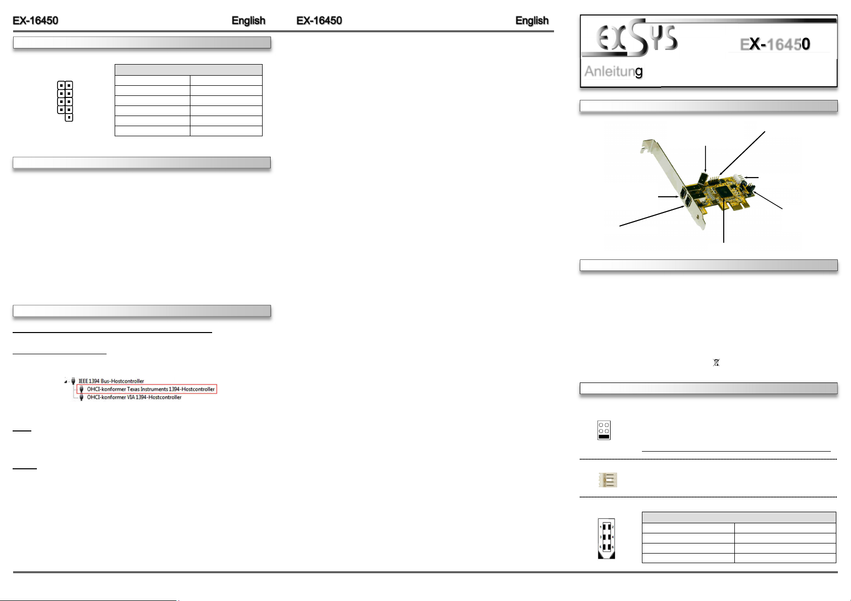
Open the >Device manager<. Now you should see at „IEEE 1394 Bus-Hostcontroller“ the
following new entry:
If you see this or a similar information the card is installed correctly.
MAC
The drivers are already integrated in MAC OS and the EX-16450 will be installed automatically.
Only at MAC OS 8.6 it requires an update before the card can be used. You can download the
update on the MAC homepage. (e.g. FireWire Support 2.8.x)
LINUX
Because each individual distribution and kernel version of Linux is different, sadly we cant
provide a installation instruction. Please refer to the installation manual for IEEE1394 ports from
your Linux version! In some newer versions of Linux the card will even be installed automatically
after starting Linux.
EX-16450
Anleitung
Vers. 1.1 / 16.09.16
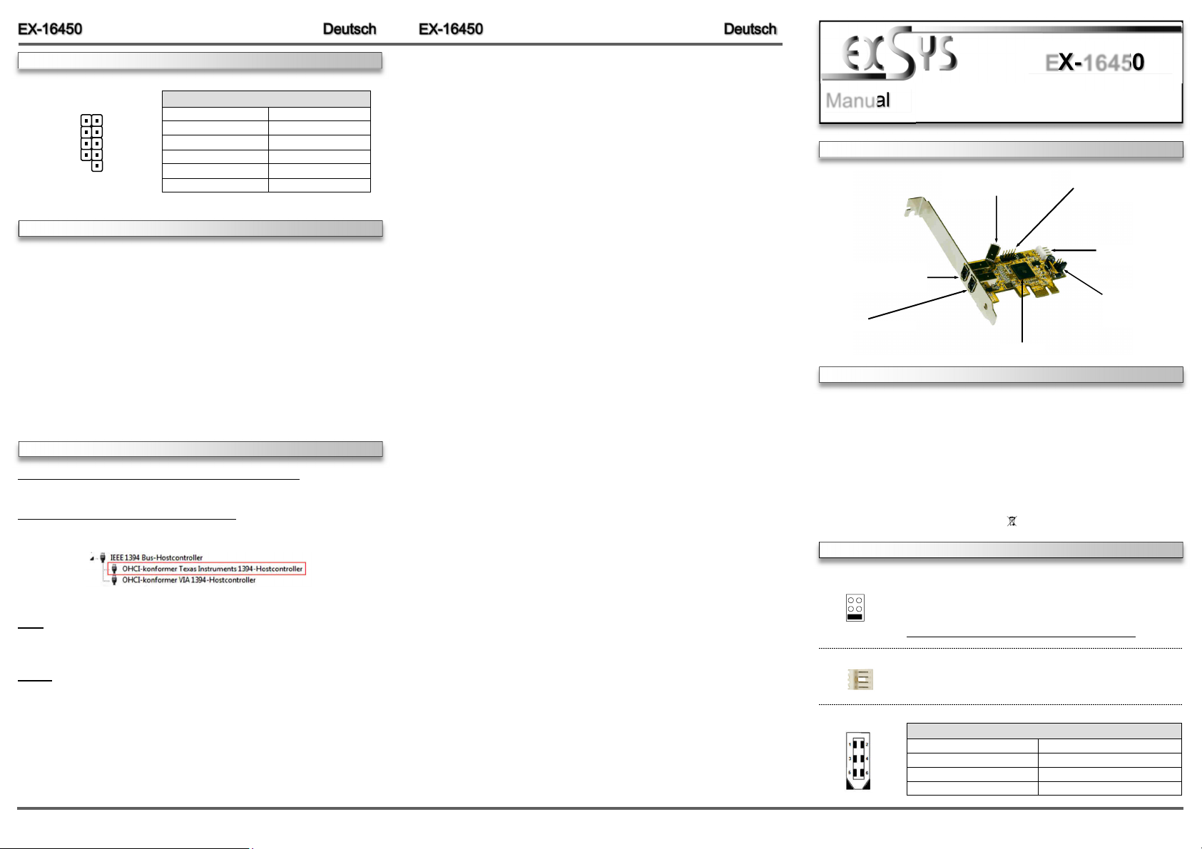
AUFBAU
J5: 1 x 6 Pin 1394a Buchs e
(Wird mit dem externen
Port J3 geteilt)
J3: 1 x 6 Pin 1394a Buchs e
(Wird mit dem internen
Port J5 geteilt)
J2: 1 x 6 Pin 1394a Buchs e
TI Chip-Set
BESCHREIBUNG & TECHNISCHE DATEN
Die EX-16450 ist eine FireWire 1394a PCI-Express Karte. Sie ist extern mit 2 und intern mit 1
FireWire 1394a Port ausgestattet. Sie unterstützt alle PCI-Express Slots von x1 bis x16. Der
serielle PCI-Express Bus unterstützt optimal die Leistung des schnellen Texas Instruments
Chipset. Die EX-16450 gewährleistet so eine sichere Datenübertragung und exzellente Performance von bis zu 400 Mbit/s! Es ist nicht möglich die I/O Adressen und Interrupts manuell
einzustellen, da die Einstellungen der Karte vom System (BIOS) und beim installieren des
Betriebssystems automatisch vorgenommen werden.
Kompatibilität: PCI-Express x1 bis x16
Betriebssysteme: Windows ME/ 2000/ XP/ Vista/ 7/ 8.x/ 10/ Server 20xx/ MAC/ Linux
Anschlüsse: 2x 6 Pin 1394a extern, 1x 6 Pin 1394a intern, 1x 10 Pin Pfostenstecker
Lieferumfang: EX-16450, Anleitung, Low Profile Bügel
Zertifikate:
CE
/ FCC / RoHS / WEEE DE97424562 / WHQL
JUMPER EINSTELLUNG & ANSCHLÜSSE
JP1:
J6:
J2 / J3 / J5:
PCI-E = Stro m vo m PCI-Express BUS (Werkseinstellung)
AUX
AUX = Stro m vo m PC-Netzteil des Rechners
(Zur Entlastung des Mainboards und zur stabilen Stromversorgung bei
PCI-E
Verwendung von Endgeräten mit hohem Stromverbrauch)
Anschluss J6 muss dann mit dem PC-Netzteil verbunden werden!
1 +5V
Für AUX Einstellung (JP1) muss J6 mit PC-Netzteil verbunden werden!
2 GND
3 GND
Sonst wird die Karte nicht mit Strom versorgt.
4 +12V
6 Pin FireWire 1394a Buchse
Pin Signal Pin Signal
1 Power 4 TPB+
2 GND 5 TPA3 TPB- 6 TPA+
J4: 1 x interne Pfostenstcker
für Front Bay Hubs
J6: Ans chl uss fü r Stec ker
vom PC-Netzteil
JP1:
Stromquelle wählen
PCI-E oder AUX
6 5
1
JUMPER EINSTELLUNG & ANSCHLÜSSE
J4:
10 Pin FireWire 1394a Pfostenstecker
TPA+
GND
TPB+
+12V
KEY
TPAGND
TPB+12V
GND
Pin Signal Pin Signal
1 NTPAD+ 6 NTPBD2 NTPAD- 7 +12V
3 GND 8 +12V
4 GND 9 NC
5 NTPBD+ 10 GND
HARDWARE INSTALLATION
Beachten Sie bitte die folgenden Installationshinweise. Da es große Unterschiede zwischen PC‘s
gibt, können wir Ihnen nur eine generelle Anleitung zum Einbau geben. Bei Unklarheiten halten Sie
sich bitte an die Bedienungsanleitung Ihres Computersystems.
1. Schalten Sie Ihren Rechner und alle angeschlossenen Peripheriegeräte aus und ziehen Sie
bei allen Geräten den Netzstecker.
2. Lösen Sie die Schrauben des Gehäuses auf der Rückseite Ihres Computers und entfernen
Sie vorsichtig das Gehäuse.
3. Gegebenenfalls installieren Sie nun die externe Stromversorgung zur Entlastung des Mainboards! (siehe Jumper Einstellung und Anschlüsse JP1 & J6)
4. Suchen Sie jetzt einen freien PCI-Express Steckplatz und stecken Sie die Karte vorsichtig in
den ausgewählten PCI-Express Steckplatz ein. Beachten Sie das die Karte korrekt eingesteckt wird und das kein Kurzschluss entsteht.
5. Danach befestigen Sie die Karte mit einer Schraube am Gehäuse.
6. Jetzt können Sie das Computergehäuse mit den Schrauben wieder schließen.
TREIBER INSTALLATION
Windows ME/ 2000/ XP/ Vista/ 7/ 8.x/ 10/ Server 20xx
Es werden keine Treiber benötigt, da die Treiber im Betriebssystem integriert sind und die Karte
wird somit automatisch installiert.
ÜBERPRÜFEN DES INSTALLIERTEN TREIBER
Öffnen Sie den >Geräte-Manager<. Jetzt müsst en Sie u nter „IEEE 1394 Bus-
Hostcontroller“ folgenden Eintrag sehen:
Ist dieser oder ein ähnlicher Eintrag vorhanden, ist die Karte richtig installiert.
MAC
Es werden keine Treiber benötigt, da die Treiber im MAC OS integriert sind und die Karte wird
somit automatisch installiert. Lediglich unter MAC OS 8.6 ist zuvor ein Update notwendig.
Dieses erhalten Sie auf der MAC Homepage. (Stichwort FireWire Support 2.8.x)
LINUX
Da sich die einzelnen Distributionen und Kernelversionen sehr voneinander unterscheiden,
können wir Ihnen keine Installationsanweisung zur Verfügung stellen. Bitte halten Sie sich an
die Installationsanweisung für IEEE1394 Anschlüsse Ihrer Linux Version.
EX-16450
Manual
Vers. 1.1 / 16.09.16
LAYOUT
J5: 1 x 6 Pin 1394a Por t
(shared with external J3)
J3: 1 x 6 Pin 1394a Por t
(shared with internal J5)
J2: 1 x 6 Pin 1394a Por t
TI Chip-Set
DESCRIPTION & TECHNICAL INFORMATION
Die EX-16450 is a plug & play high-speed FireWire IEEE1394a expansion card for the PCIExpress Bus. The EX-16450 provides 2 external and 1 internal FireWire 1394a port. It supports
all PCI-Express slots x1 to x16. The EX-16450 design fully utilize the Texas Instruments chipset, which represents the latest in high speed IEEE1394 interface technology. In combination
with the fast PCI-Express bus it provides a secure and very high data transfer on each single
port. It uses data transfer rates up to 400Mbit/s. It is not possible to change the address or IRQ
settings manually, they will be obtained automatically by the system (BIOS) and operating
system.
Compatibility: PCI-Express x1 to x16
Operating Systems: Windows ME/ 2000/ XP/ Vista/ 7/ 8.x/ 10/ Server 20xx/ MAC/ Linux
Connectors: 2x extern 6 Pin 1394a, 1x intern 6 Pin 1394a, 1x 10 Pin Connector
Extent of delivery: EX-16450, Manual, Low Profile Bracket
Certificates:
CE
/ FCC / RoHS / WEEE DE97424562 / WHQL
JUMPER SETTING & CONNECTORS
JP1:
J6:
J2 / J3 / J5:
PCI-E = Power from PCI-Express BUS (Factory Setting)
AUX
AUX = Power from PC power supply
(Direct power from PC power supply, provide an sufficient power for
PCI-E
devices with high power consumption)
Connector J6 must be connected with PC power supply!
1 +5V
For aux power (JP1), J6 must be connected to PC power supply!
2 GND
3 GND
If not, the card won’t work.
4 +12V
6 Pin FireWire 1394a Port
Pin Signal Pin Signal
1 Power 4 TPB+
2 GND 5 TPA3 TPB- 6 TPA+
J4: 1 x internal 10 Pin
Connector for Front Bay
Hubs
J6: Connector for
PC Power Supply
JP1:
Select power source
PCI-E or AUX
2 3
4
 Loading...