

Page 1

1
Thank you for purchasing this RS232/422/485 3-in-1 Serial to USB
Adapter. It is an intelligent expansion module that connects to a PC or
server via the Universal Serial Bus (USB), providing high-speed serial
connectivity. The serial ports are fully compatible with RS232/422/485
standard by the bundled virtual COM port drivers. It provides a universal
mounting Kit which can be mounted on wall, DIN Rail and other
surfaces. Moreover, with the 4KV isolation, 15KV ESD surge protection
and USB Screw Lock Mechanism features, it is an ideal solution for
most critical applications.
EX-1331-4KVIS
RS232/422/485 3-in-1 Serial to USB Adapter
(w/ 4KV Isolation, 15KV ESD Surge Protection)
2. Connector Layout
1. Introduction
Upstream
USB Port
RS232/422/485 Port
Mounting Kit for
Wall-mounting and
DIN ail Mounting
Options
Mode-Setting
Switches are on its
backside
Page 2
RS232/422/485 3-in-1 Serial to USB Adapter w/ 4KV Isolation and Surge Protection
2
Features:
Provides 1 RS232/422/485 Serial Port over USB Port
Provides 1 DSUB-9 Connector
Supports USB2.0 High Speed (480Mbps) Data Rate
Supports USB Screw Lock Mechanism Enhances Reliability
Baud Rate from 300 bps to 921.6Kbps
Supports 7,8 Data Bits
Odd, Even, Mark, Space, or None parity mode
Supports 1, or 2 Stop Bits
Supports USB Bus Power
Supports 4KVrms Isolation and 15KV ESD Surge Protection
Supports Win98, Me, XP, CE, Win2000, 2003, Vista and Win 7, 8.x,
10 and Linux
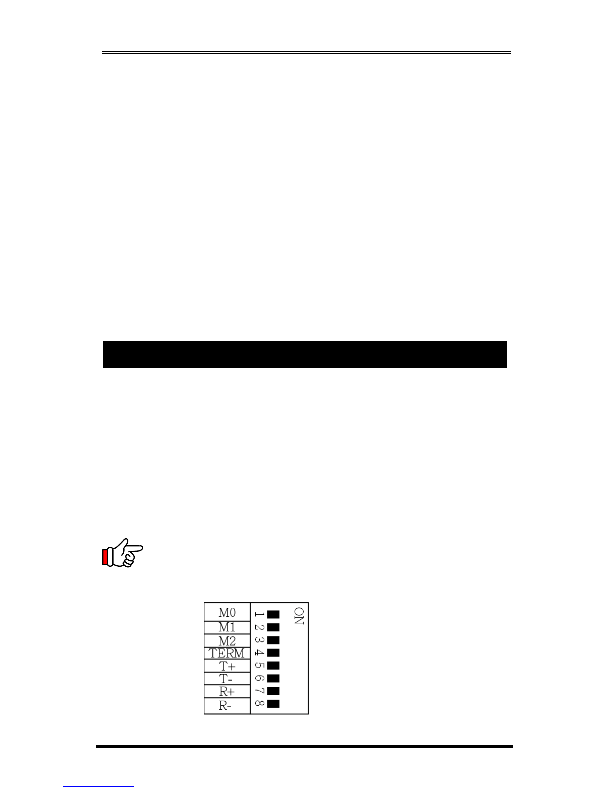
There is an 8-pin DIP switch on the back side of the box for the required
settings. Their functions are described as follows:
Mode Settings:
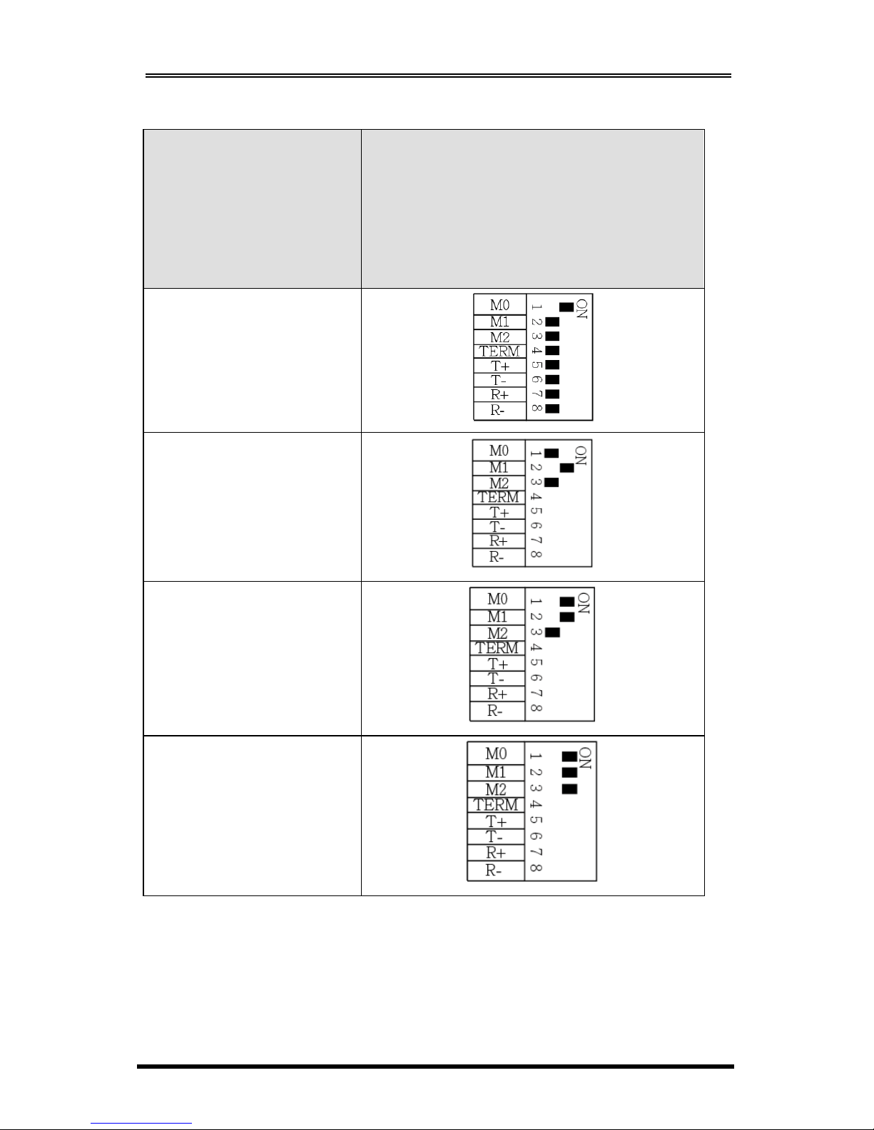
The DIP switch has 8 pins, the first 3 pins (M0, M1, M2) are for mode
settings (RS232, RS485-2wire, RS485-4wire or RS422 modes), pin 4
(TERM) is to enable or disable terminator. Pin 5 and 6 (T+, T-) are to enable
or disable the bias for TX+ and TX- signals. Pin 7 and 8 (R+, R-) are to
enable or disable the bias for RX+ and RX- signals.
Note:
Pin 5 to 8 are designed for RS422 and RS485 only and
should be set to
OFF
when you are setting the port to RS232 mode.
3. Mode Switch Settings
Page 3
RS232/422/485 3-in-1 Serial to USB Adapter w/ 4KV Isolation and Surge Protection
3
Modes
Settings
M0
M1
M2
(ON)
RS232
(Default)
RS485-2W
RS485-4W
RS422
Page 4
RS232/422/485 3-in-1 Serial to USB Adapter w/ 4KV Isolation and Surge Protection
4
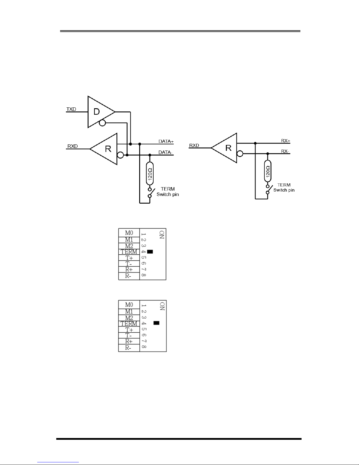
Termination Resistor Settings:
The pin 4 of the DIP switch is to enable the 120 Ohm termination resistor
between RX+ and RX- signals.
Terminator disabled (OFF, default):
Terminator enabled (ON):
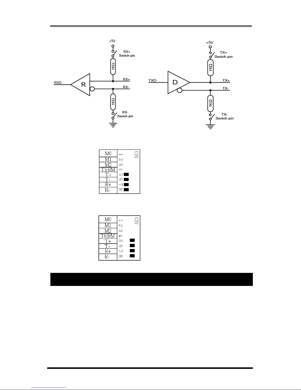
Bias Resistors Enable/Disable:
Pin 5 to 8 of the DIP switch are to enable (ON) or disable (OFF) the 4 bias
resistors for TX+, TX-, RX+, RX- signals respectively. Please note that you
have to set them to OFF if you are setting the port in RS232 mode.
DIP Switch Pin 4
DIP Switch Pin 4
RS485-2wire mode:
RS485-4wire or RS422 mode:
Page 5
RS232/422/485 3-in-1 Serial to USB Adapter w/ 4KV Isolation and Surge Protection
5
Disable (default) all 4 Bias resistors for TX+, TX-, RX+ and RX-:
Enable all 4 Bias resistors for TX+, TX-, RX+ and RX-:
This Adapter Cable can be hot-plugged to the USB port of your computer
due to the specifications of USB. It supports the following operating systems.
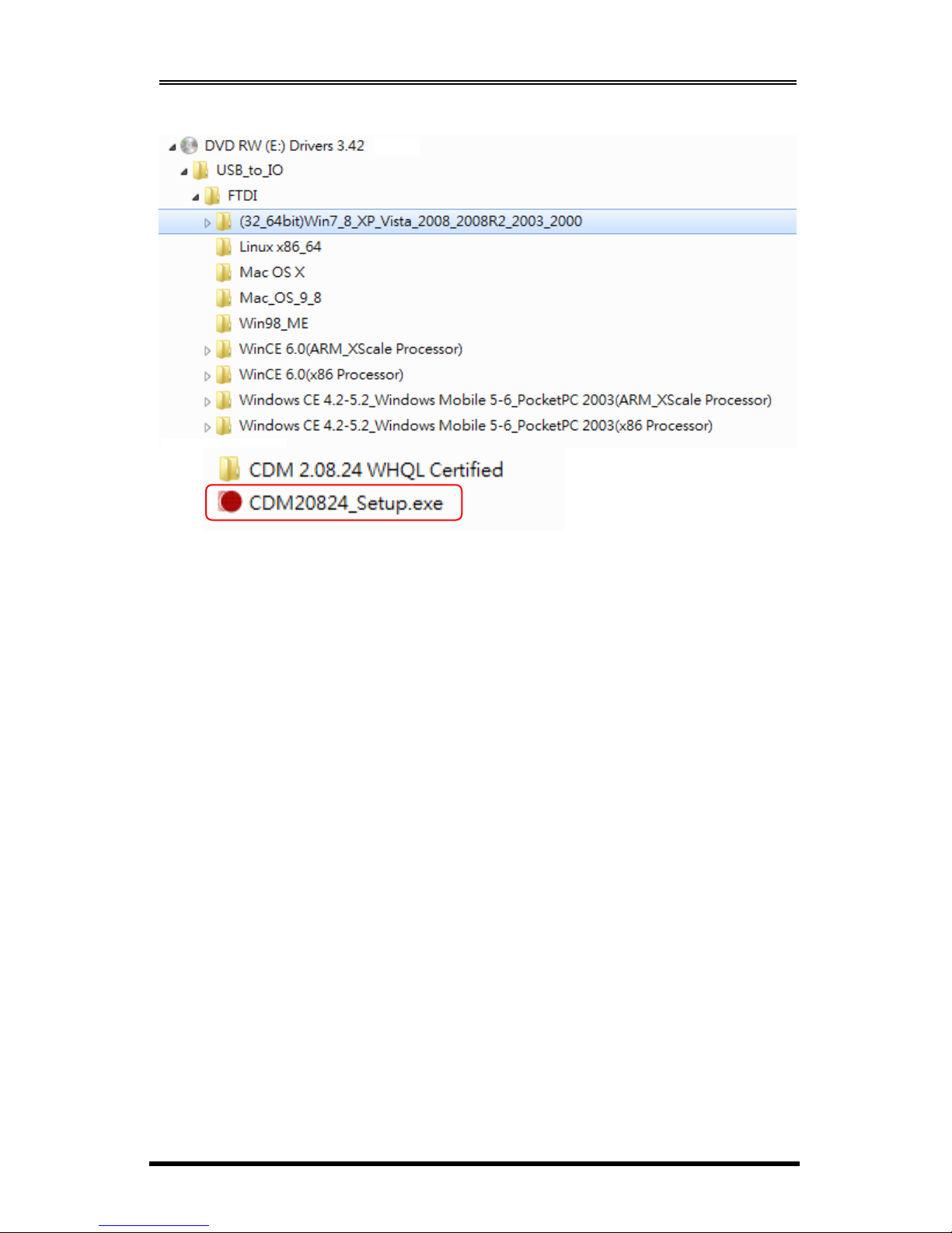
The drivers were shipped in the following folders on the supplied driver CD.
1. Driver Locations on the CD
These instructions are for installing the drivers from the CD supplied with
the product. If you are installing drivers for Windows, when prompted for the
location of the drivers, specify your DVD drive and the locations according
to the following folder list:
4. Installing Drivers
DIP Switch Pin 5
DIP Switch Pin 6
DIP Switch Pin 7
DIP Switch Pin 8
Page 6
RS232/422/485 3-in-1 Serial to USB Adapter w/ 4KV Isolation and Surge Protection
6
2.
Installing Drivers for (32-bit and 64-bit) Win7, 8.x, 10, XP, Vista,
2008, 2003 and 2000:
Insert the Driver CD supplied with the Adapter Cable.
Run (or double click) the Installer Program (e.g.
CDM20824.exe
) in
the following folder of the driver CD:
\USB_to_IO\FTDI\(32_64bit)Win7_8_XP_Vista_2008_2008R2_2003_2000
Follow the instructions of the installer program to complete the
setup procedures.
Plugging the Adapter Cable will hook the drivers into the Windows
kernel automatically.
Page 7

RS232/422/485 3-in-1 Serial to USB Adapter w/ 4KV Isolation and Surge Protection
7
The pin assignment of the DB9 male connector of the Adapter Cable is
dependent on its operation modes. Please refer to the following figure for
the corresponding mode:
1. RS232 Pin Assignment:
RS232 DB9(Male) to DB9(Male) Wiring:
5. Connector Pin Assignments
DB9 Male(Adapter Cable) DB9 Male(Serial Device)
1 DCD 1 DCD
2 RXD 2 RXD
3 TXD 3 TXD
4 DTR 4 DTR
5 GND 5 GND
6 DSR 6 DSR
7 RTS 7 RTS
8 CTS 8 CTS
Page 8
RS232/422/485 3-in-1 Serial to USB Adapter w/ 4KV Isolation and Surge Protection
8
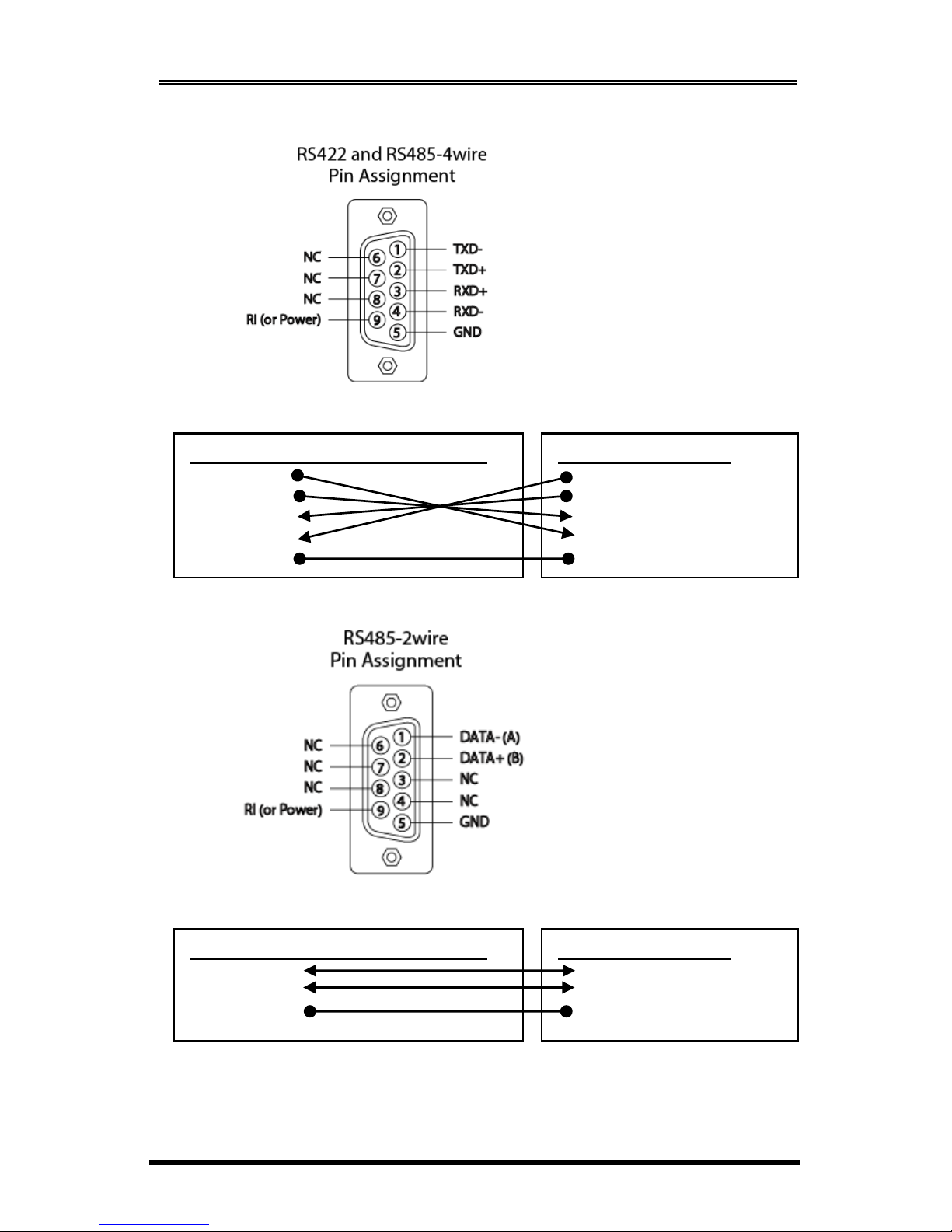
2. RS422 and RS485-4wire Pin Assignment:
RS422 Cable Wiring:
3. RS485-2wire Pin Assignment:
RS485-2wire Cable Wiring:
DB9 Male (Adapter Cable)
1 TXD 2 TXD+
3 RXD+
4 RXD 5 GND
(RS422 Device)
1 TXD 2 TXD+
3 RXD+
4 RXD 5 GND
DB9 Male (Adapter Cable)
1 DATA 2 DATA+
5 GND
(RS485 Device)
1 DATA 2 DATA+
5 GND
Page 9
RS232/422/485 3-in-1 Serial to USB Adapter w/ 4KV Isolation and Surge Protection
9
Type
Specifications
Device Connector
Cable
Host Connector
Number of Ports
RS-232 Signals
RS422 Signals
RS485-4wire Signals
RS485-2wire
Baud Rate
Data Bits
Stop Bits
I/O address/IRQ
Parity
Flow Control
Isolation
ESD Surge Protection
Power Requirement
Operating Temperature
Operating Humidity
Storage Temperature
DB9 male
USB
USB Type-B (Supports Screw-lock)
1
TXD, RXD, RTS, CTS, DTR, DSR, DCD,
GND
TXD+, TXD-, RXD+, RXD-, GND
TXD+, TXD-, RXD+, RXD-, GND
DATA+(B)/DATA-(A)
110 bps to 921.6Kbps
5,6,7,8
1, 1.5, 2
Plug-and-Play (various)
None, Even, Odd
RTS/CTS, XON/XOFF
4KVrms
15KV
5V/110mA (USB Bus Powered)
0 to 55C(32 to 132F)
5 to 95% RH
-20 to 85C (-4 to 185F)
5. Specifications
 Loading...