

Exprezo EZ-108, EZ-116 User Manual

User’s Manual
Version 1.0
March 2015
EZswitch-0B-v1.0-E

Disclaimer
Information in this document is subject to change without notice. The manufacturer does not make any representations
or warranties (implied or otherwise) regarding the accuracy and completeness of this document and shall in no event be
liable for any loss of profit or any other commercial damage, including but not limited to special, incidental, consequenti al,
or other damages.
No part of this document may be reproduced or transmitted in any form by any means, electronic or mechanical,
including photocopying, recording or information recording and retrieval s ystems without the express written permission
of the manufacturer.
All brand names and product names used in this document are trademarks, or registered trademarks of their respective
holders.
FCC Statement
This device generates and uses radio frequency and may cause interference to radio and television rece ption if not
installed and used properly. This has been tested and found to comply with the limits of a Class B computing device in
accordance with the specifications in Part 15 of the FCC Rules. These specifications are designed to provide reason able
protection against such interference in a residential installation. However, there is no guarantee that interference will not
occur in a particular installation. If this device does cause harmful interference to radio or television reception, which can
be determined by plugging the device in and out, the user can try to correct the interference by one or more of the
following measures:
Reorient or relocate the receiving antenna.
Increase the separation between the device and receiver.
Connect the computer into an outlet on a circuit different from that to which the receiver is connected.
Consult the dealer or an experienced radio/TV technician for help.
Rack-mount Safety Instructions
Elevated Operating Ambient –
If installed in a closed or multi-unit rack assembly, the operating ambient temperature of the rack environment may
be greater than room ambient. Therefore, consideration should be given to installing the equipment in an
environment compatible with the maximum ambient temperature (Tma) specified by the manufacturer.
Reduced Air Flow –
Installation of the equipment in a rack should be such that the amount of air flow required for safe operation of the
equipment is not compromised.
Mechanical Loading –
Mounting of the equipment in the rack should be such that a hazardous condition is not achieved due to uneven
mechanical loading.
Circuit Overloading –
Consideration should be given to the connection of the equipment to the supply circuit and the effect that
overloading of the circuits might have on overcurrent protection and supply wiring. Appropriate consideration of
equipment nameplate ratings should be used when addressing this conc ern.
Reliable Earthing –
Reliable earthing of rack-mounted equipment should be maintained. Particular attention should be given to supply
connections other than direct connections to the branch circuit (e.g. use of power strips).

i
Contents
1. INTRODUCTION ........................................................................................................................................ 1
2. SPECIFICATION ........................................................................................................................................ 2
3. SYSTEM REQUIREMENTS ..................................................................................................................... 3
4. INSTALLATION .......................................................................................................................................... 3
4.1. FRONT VIEW ........................................................................................................................................ 3
4.2. REAR VIEW .......................................................................................................................................... 4
4.3. INSTALL A KVM SWITCH (SINGLE-TIER INSTALLATION) .................................................................... 4
4.3.1. Installation Guidelines ......................................................................................................... 4
4.3.2. Console Connection ............................................................................................................. 4
4.3.3. System Connection .............................................................................................................. 5
4.4. CASCADE KVM SWITCHES (MULTI-TIER INSTALLATION) .................................................................. 7
4.5. FIRMWARE UPGRADE PORT ................................................................................................................ 9
4.6. RACK-MOUNT THE KVM SWITCH ....................................................................................................... 9
5. OPERATION ............................................................................................................................................... 9
6. HOT KEY OPERATION........................................................................................................................... 10
6.1. TRIGGER THE OSD MENU ................................................................................................................ 10
6.2. SET THE LEADING HOT KEY ............................................................................................................. 10
6.3. CHANNEL SELECTION IN A SINGLE-TIER KVM SYSTEM .................................................................. 10
6.3.1. Select a Specific Channel ................................................................................................. 10
6.3.2. Channel Switching Using Arrow Keys ........................................................................... 11
6.3.3. Channel Switching Using the <AL T> Key ..................................................................... 1 1
6.4. CHANNEL SELECTION IN A MULTI-TIER KVM SYSTEM .................................................................... 12
6.5. DISABLE OR ENABLE THE BUZZER ................................................................................................... 13
6.6. AUTO-SCAN FUNCTION ..................................................................................................................... 13
6.6.1. Enable the Auto-Scan Function ....................................................................................... 13
6.6.2. Disable the Auto-Scan Function ...................................................................................... 14
6.6.3. Different Auto-Scan Modes ............................................................................................... 14
6.6.4. Auto-Scan Time Interval .................................................................................................... 14
6.7. CONSOLE LOCK ................................................................................................................................ 15
7. OSD OPERATION ................................................................................................................................... 15
7.1. OSD MAIN MENU .............................................................................................................................. 15
7.1.1. Tier Number .......................................................................................................................... 15
7.1.2. Channel Name ...................................................................................................................... 15
7.1.3. Computer & KVM Switch Status ...................................................................................... 16

ii
7.1.4.
Currently Selected Channel Number.............................................................................. 16
7.1.5. Parent Channel Number .................................................................................................... 17
7.1.6. Page Down / Up Indicator .................................................................................................. 17
7.1.7. Function Keys Menu ........................................................................................................... 17
7.2. CHANNEL SELECTION USING THE OSD ........................................................................................... 17
7.2.1. Select a Channel .................................................................................................................. 17
7.2.2. Select a Second- or Third-Tier Channel ........................................................................ 18
7.2.3. Return to the Upper-Tier OSD .......................................................................................... 18
7.3. SETUP MENU ..................................................................................................................................... 18
7.3.1. Scan Mode ............................................................................................................................ 19
7.3.2. Scan Time .............................................................................................................................. 19
7.3.3. Banner Time ......................................................................................................................... 19
7.3.4. Position .................................................................................................................................. 19
7.3.5. Hot Key .................................................................................................................................. 20
7.3.6. Sound ..................................................................................................................................... 20
7.3.7. Language ............................................................................................................................... 20
7.4. AUTO-SCAN USING THE OSD .......................................................................................................... 21
7.4.1. Enable the Auto-Scan Function ....................................................................................... 21
7.4.2. Disable the Auto-Scan Function ...................................................................................... 21
7.4.3. Different Auto-Scan Modes ............................................................................................... 22
7.4.4. Auto-Scan Time Interval .................................................................................................... 22
7.5. CONSOLE LOCK USING THE OSD .................................................................................................... 22
7.6. RENAME A CHANNEL ......................................................................................................................... 23
7.7. SECURITY SETUP .............................................................................................................................. 23
7.7.1. Security Mode Login .......................................................................................................... 23
7.7.2. Security Mode ...................................................................................................................... 24
7.7.3. Change the Administrator Password ............................................................................. 24
7.7.4. User Account Settings ....................................................................................................... 25
7.7.5. User Authorization Settings ............................................................................................. 25
7.8. PORT LOCK ....................................................................................................................................... 26
7.8.1. Lock a Channel Port ........................................................................................................... 26
7.8.2. Select a Locked Channel ................................................................................................... 27
7.8.3. Unlock a Channel Port ....................................................................................................... 27
7.9. EXIT OSD .......................................................................................................................................... 27
8. SPECIAL SUN KEY EMULATION ........................................................................................................ 28
9. TROUBLESHOOTING ............................................................................................................................ 29
10. FIRMWARE UPGRADE .......................................................................................................................... 30

iii
11.
TIERING WITH DOMINION KX II .......................................................................................................... 35
11.1. CONNECT EZSWITCH TO DOMINION KX II ........................................................................................ 35
11.2. CONFIGURE DOMINION KX II ............................................................................................................ 35
11.3. REMOTE ACCESS TO AN EZSWITCH CHANNEL ................................................................................ 37
12. KEYBOARD AND MOUSE COMPATIBILITY ..................................................................................... 38
12.1. MOUSE COMPATIBILITY TABLE ......................................................................................................... 38
12.2. KEYBOARD COMPATIBILITY TABLE .................................................................................................. 43

iv

1
1. Introduction
Thank you for purchasing EZswitch, an 8-port or 16-port keyboard/video/mouse
(KVM) switch. The product enables you to control 8 or 16 computers or servers from
one console with PS/2 or USB input devices and a regular monitor.
Features
Supports the PS/2 and USB keyboard and mouse
Computer connection via PS/2 or USB interface
Fully compliant with the USB 1.1/ 2.0 specification
Multi-platform support, including Windows, Linux, Mac OS9/OSX, and Sun
Microsystems
Supports VGA resolutions up to 2048 x 1536
Intuitive On-Screen-Display (OSD) interface for simple operation
Supports chain cascading function on the OSD
Expands to 4,096 computers via a 3-tier daisy chaining configuration (using
16-port KVM switches)
No special configuration required for cascading KVM switches
Supports tiering with Raritan’s Dominion® KX II models (see the section “11.
Tiering with Dominion KX II”)
Emulates a PS/2 or USB keyboard on each connected computer for normal boot
without any keyboard error
Hot swappable components with no impact on the operation
Quick channel switching through:
- Push buttons on the KVM switch
- Hot keys using the keyboard
- OSD interface
Auto-scan function for automatically cycling through all channels
An LED display for computer status monitoring
Provides a beeper for indication of channel switching
Rack-mountable in a 19” system rack (1U)
Firmware upgradeable
Package Contents
The product package includes the following items:
One 8-port or 16-port EZswitch
One user’s manual (with warranty card included)
One power adaptor
One rackmount bracket kit
Custom KVM cables

2
2. Specification
Specification
Maximum number of computers 8 or 16
Channel selection Push buttons, hot key or OSD interface
LEDs
Red ones for indicating the computer selection
Green ones for indicating the computer accessibility
Channel ports:
Video 8 or 16 HDB-15 female connectors
(KB/MS) (PS/2 & USB signals combined)
Console ports:
PS/2 keyboard One 6-pin mini-DIN female connector
PS/2 mouse One 6-pin mini-DIN female connector
Video One HDB-15 female connector
USB keyboard One USB A type female connector
USB mouse One USB A type female connector
Auto-Scan interval Adjustable via the OSD
DDC, DDC2 monitor resolution Up to 2048 x1536@65Hz
Hot swappable Yes
Operating systems
Windows 98SE/Me/2000/XP/2003/Vista/7,
Linux, Mac OS9/OSX and Sun Microsystems
Power supply External power adaptor
Dimensions (L x W x H) 44 x 15.7 x 4.5 cm (17.3 x 6.1 x 1.5 inch)
Weight 1750g / 1900g
Housing material Metal
Operating temperature 32~122°F (0~50°C)
Humidity 0%~80%RH
Firmware upgrade port Mini USB female
3
3. System Requirements
Console Requirements:
A VGA, SVGA or Multisync monitor with high resolution capability
PS/2 or USB keyboard and mouse
Computer (Server) Requirements:
Equipped with a VGA, SVGA or Multisync video card
Equipped with USB A type ports or PS/2 6-pin mini-DIN connectors for keyboard
and mouse
Cable Requirements:
Custom KVM cables
Note: To purchase these cables, contact your dealer or Raritan.
4. Installation
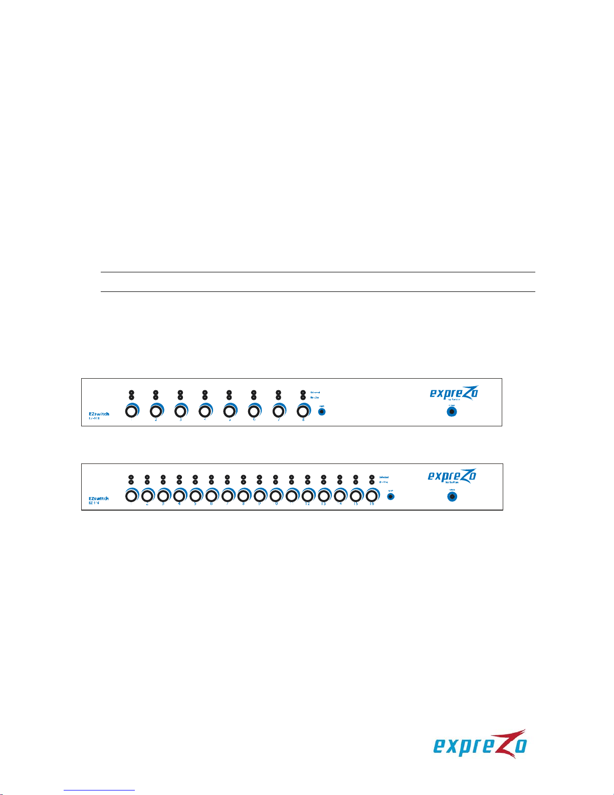
4.1. Front View
Figure 1: Front view of the 8-port switch
Figure 2: Front view of the 16-port switch
LED Indicators:
“Selected” LEDs:
A lit RED LED indicates that the computer connected to the corresponding
channel is selected.
“On-Line” LEDs:
A lit GREEN LED indicates that a computer is physically connected to the
corresponding channel and is ready to access.
4
Reset Switch:
Press the Reset switch when you want to reset the system. This switch must be
pressed with a pointed object, such as a paper clip or a ball-point pen.
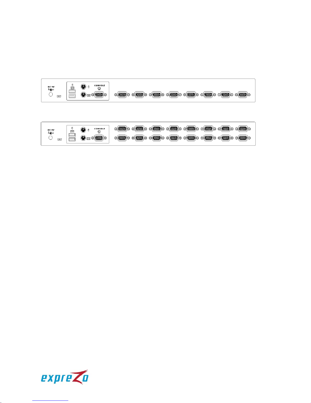
4.2. Rear View
Figure 3: Rear view of the 8-port switch
Figure 4: Rear view of the 16-port switch
4.3. Install a KVM Switch (Single-Tier Installation)
4.3.1. Installation Guidelines
All computers and devices must be turned OFF prior to installation.
Disconnect power cords from the computers implemented with the Keyboard
Power On function prior to installation, or the KVM switch may not work properly.
Computers running Windows 98 must be connected to a KVM switch via PS/2
ports because Windows 98 does not support initial installation through the USB
HID driver.
Old computers may require USB setting adjustment in the BIOS to enable the
USB interface.
There is no guarantee that the EZswitch KVM switch can fully support a USB
keyboard via a USB hub.
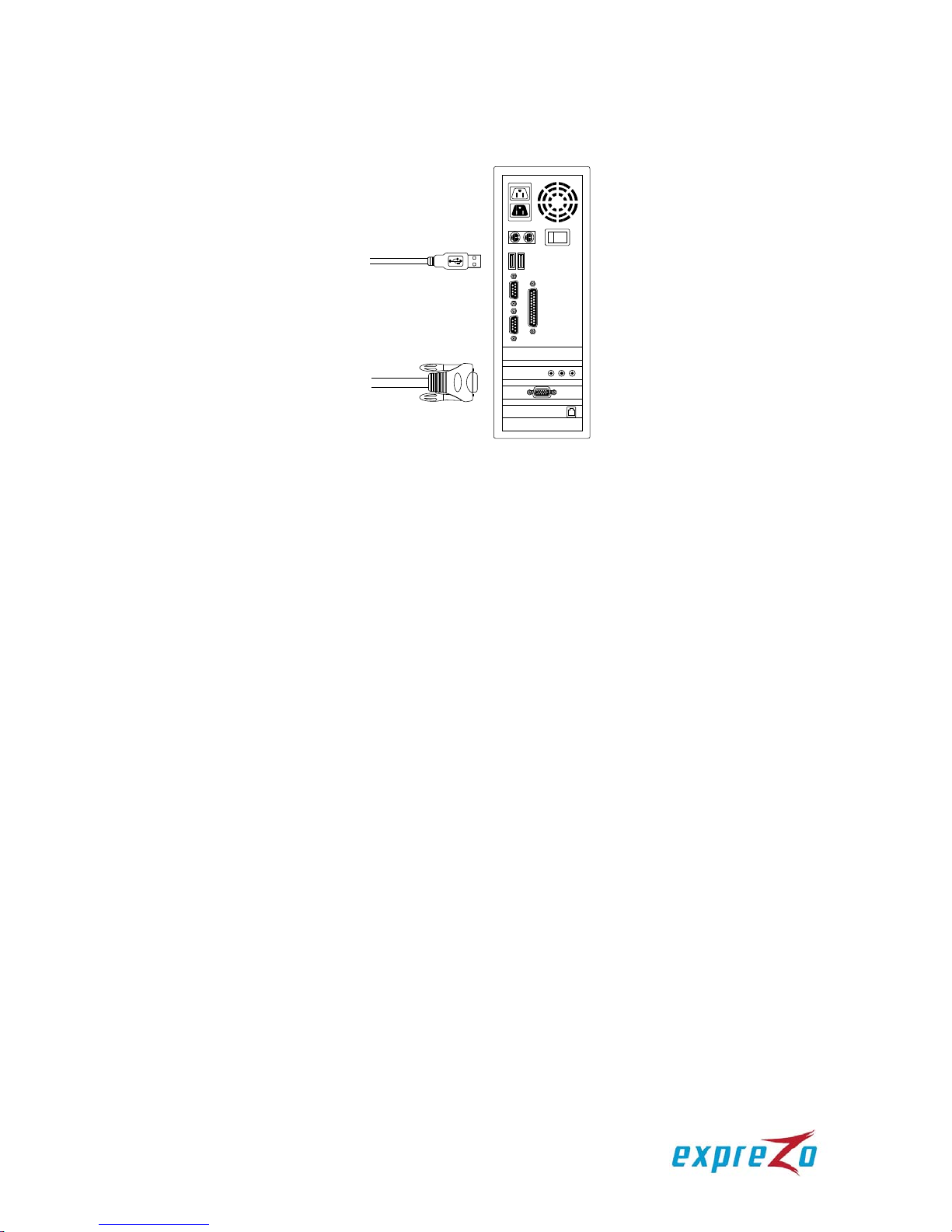
4.3.2. Console Connection
Connect a keyboard, mouse and monitor to the console ports on the real panel
of EZswitch (see Figure 5).
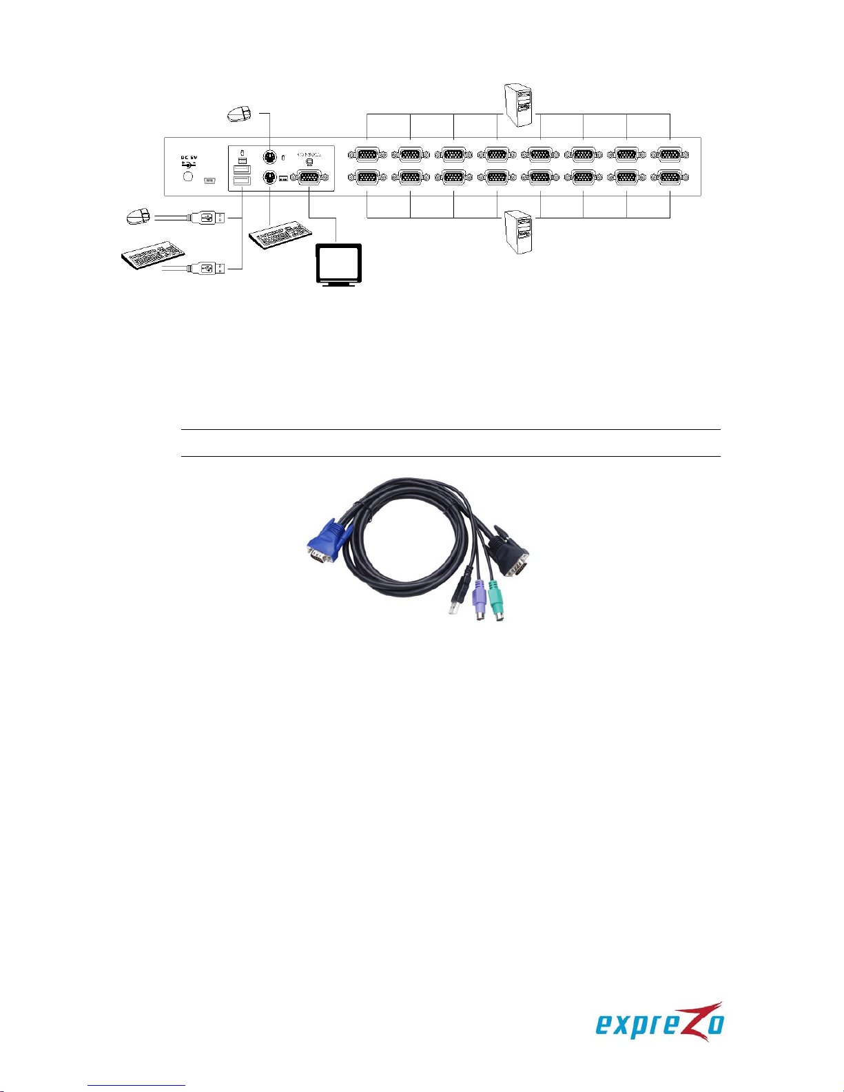
5
Figure 5: Console connection
4.3.3. System Connection
You need a custom combo cable to connect a computer to the EZswitch KVM
switch.
Note: If needed, contact your dealer or Raritan to purchase the custom KVM cables.
Figure 6: Custom KVM cable
6
There are three different ways to connect a computer. See the instructions
below:
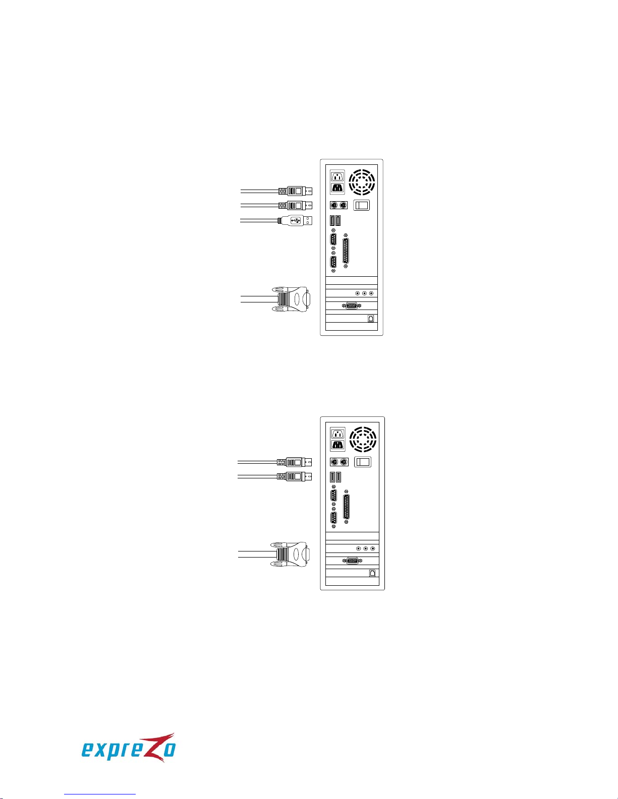
A. Plug the combo cable’s USB, PS/2 keyboard, PS/2 mouse and VGA
connectors into a computer (see Figure 7). This method is highly
recommended for computer connection.
Figure 7: USB, PS/2 and VGA connections
B. Plug only the combo cable’s PS/2 keyboard, PS/2 mouse and VGA
connectors into a computer (see Figure 8).
Figure 8: PS/2 and VGA connections
7
C. Plug only the combo cable’s USB and VGA connectors into a computer
(see Figure 9).
Figure 9: USB and VGA connections
4.4. Cascade KVM Switches (Multi-Tier Installation)
You can cascade either the 8-port or the 16-port EZswitch products up to 3 tiers,
expanding the number of computers to 64, 256 or 4096 computers. No special
configuration is required for the cascade.
After completing the installation, the system automatically configures the Master and
Slave KVM switches. The Master KVM switch is the first-tier KVM switch and Slave
KVM switches are second-tier or third-tier KVM switches. You can select the
computers connected to the Master or Slave KVM switches at any time.
To cascade KVM switches, follow these instructions:
A. Turn OFF all computers and devices.
B. Connect one or more Slave KVM switches to the channel ports on the Master
KVM switch using the custom combo cables (see Figure 6). The connection
between KVM switches must be done via the PS/2 interface (see Figure 7 &
Figure 8
).
C. Connect a USB or PS/2 keyboard and mouse to the console ports on the Master
KVM switch.
D. Connect a power adaptor to the Master KVM switch.
E. Connect computers to available channel ports on the Master KVM switch.
F. Connect a power adaptor to each Slave KVM switch.
G. Connect computers to available channel ports on the Slave KVM switch.
H. Turn on each device in the folloiwng sequence:
1. Master KVM switch
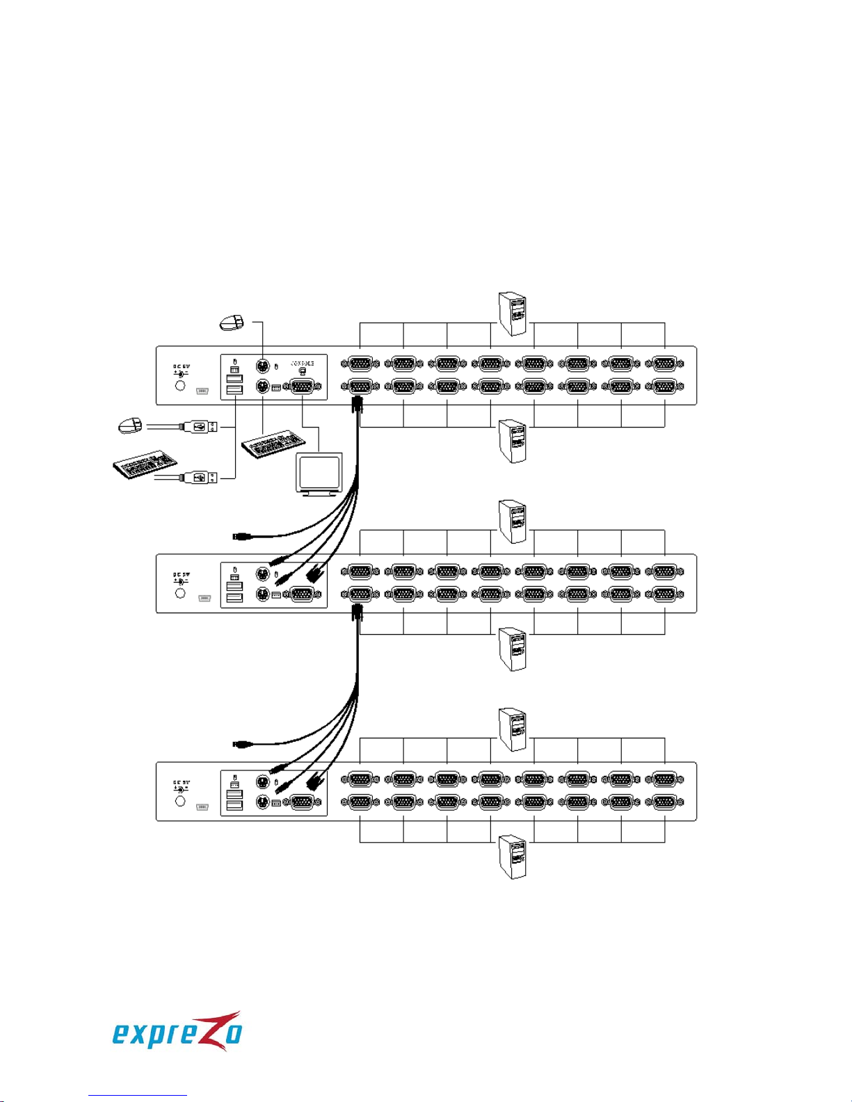
8
2. Second-tier Slave KVM switches (connected to the Master KVM switch), if
any
3. Third-tier Slave KVM switches (connected to the second-tier Slave KVM
switches), if any
4. All computers connected to KVM switches
I. Connect other devices such as a montior or new computers to the Master KVM
switch before turning on the additional devices.
J. Now you can hot swap or hot plug any devices into any KVM switches. Both of
8-port and 16-port KVM switches support hot plug and hot swap functions.
Figure 10: Cascaded configuration
9
4.5. Firmware Upgrade Port
The min-USB female connector on the rear of the EZswitch KVM switch is used for
firmware upgrade. Contact your dealer or Raritan when you need to update the
firmware.
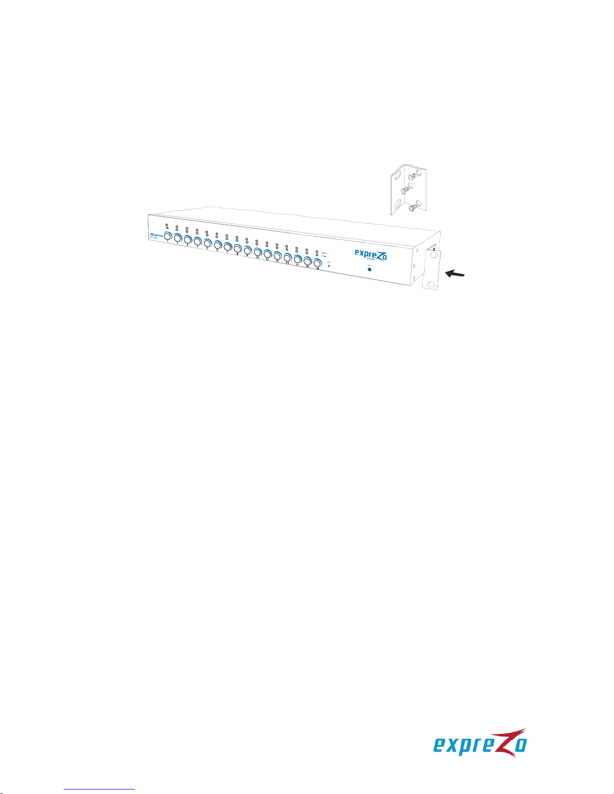
4.6. Rack-Mount the KVM Switch
Figure 11: Rack mounting
This section describes how to attach mounting brackets to the KVM switch for
rack-mounting it on a standard 19-inch rack.
A. Screw the mounting brackets to the sides of the KVM switch (see Figure 11).
B. Mount the KVM switch on a rack.
5. Operation
You can control computers connected to the EZswitch KVM switch by using the
push buttons, hot keys or OSD interface.
Push button operation:
Press a front panel push button to select the corresponding computer and
operate it.
Hot Key operation:
See the section “6. Hot Key Operation.”
OSD operation:
See the section “7. OSD Operation.”

10
6. Hot Key Operation
6.1. Trigger the OSD Menu
Press <Scroll Lock> twice and then press <Enter>. The OSD main menu will be
displayed on the screen. All of the KVM settings can be configured through the OSD
interface. Some KVM functions can also be performed using the OSD.
<Scroll Lock> + <Scroll Lock> + <Enter>
6.2. Set the Leading Hot Key
A hot key allows you to quickly perform a specific function.
Its leading key is set to <Scroll Lock> by default. You can change this key if needed.
To change the leading hot key, follow this procedure:
Press <CTRL> twice, then the new leading hot key, and finally press <Enter>. The
leading hot key is changed then.
Available leading hot key options include <Scroll Lock>, <Num Lock> and <Caps
Lock>.
Examples:
To set the leading hot key to <Scroll Lock>:
<CTRL> + <CTRL> + <Scroll Lock > + <Enter>
To set the leading hot key to <Num Lock>:
<CTRL> + <CTRL> + <Num Lock> + <Enter>
To set the leading hot key to <Caps Lock>:
<CTRL> + <CTRL> + <Caps Lock> + <Enter>
Tip: You can also change the leading hot key by pressing <F1> in the OSD main menu. See the
section “7.3.5 Hot Key.”
6.3. Channel Selection in a Single-Tier KVM System
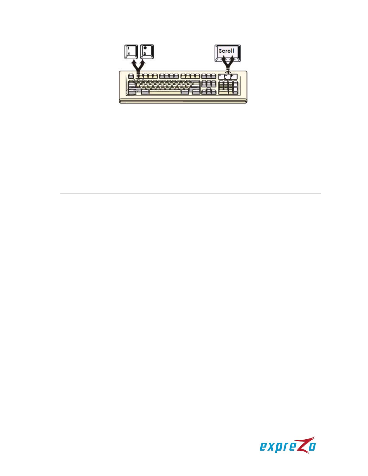
6.3.1. Select a Specific Channel
You can select a connected computer by using the hot key combination: first
press <Scroll Lock> twice, then a number (1~16) corresponding to the channel
number of the computer that you want to control, and finally press <Enter>.
11
Figure 12: Channel selection hot key
Examples:
<Scroll Lock> + <Scroll Lock> + <1> + <Enter>
<Scroll Lock> + <Scroll Lock> + <2> + <Enter>
…
<Scroll Lock> + <Scroll Lock> + <16> + <Enter>
Tip: You can also select a computer in the OSD menu. See the section “7.2 Channel Selection
Using the OSD.”
6.3.2. Channel Switching Using Arrow Keys
To switch to the prior or next channel that is adjacent to the current channel, do
this: first press <Scroll Lock> twice, and then the <Left arrow> or <Right
arrow> key.
To switch to the prior channel:
<Scroll Lock> + <Scroll Lock> + <Left arrow>
To switch to the next channel:
<Scroll Lock> + <Scroll Lock> + <Right arrow>
6.3.3. Channel Switching Using the <ALT> Key
You can also switch to the prior or next channel using the <ALT> key
combinations.
A. Enable the <ALT> channel switching function:
By default, the channel switching function using the <ALT> key is disabled.
To enable it, press <Scroll Lock> twice, then <ALT> and finally <Enter>. To
disable the function, press the same key combinations again.

12
B. Switch to the prior or next channel using the <ALT> key:
Press the <Left ALT> or <Right AL T> key twice, and the system will
automatically switch to the prior or next channel.
Enable/disable the <ALT> channel switching function:
<Scroll Lock> + <Scroll Lock> + <ALT> + <Enter>
Switch to the prior channel:
<Left ALT> + <Left ALT>
Switch to the next channel:
<Right ALT> + <Right ALT>
6.4. Channel Selection in a Multi-Tier KVM System
A cascaded KVM system allows you to select a channel at any tier directly. Use the
following hot key combination to select a channel:
Press <Scroll Lock> twice, the <D> key, then the number of the channel (1~16)
where the computer or the second or third tier is connected, and finally press
<Enter>.
Select a channel at the first tier:
<Scroll Lock> + <Scroll Lock> + <D> + <1st tier channel number> + <Enter>
Select a channel at the second tier:
<Scroll Lock> + <Scroll Lock> + <D> + <1st tier channel number>
+ <D> + <2nd tier channel number> + <Enter>
Select a channel at the third tier:
<Scroll Lock> + <Scroll Lock> + <D> + <1st tier channel number>
+ <D> + <2nd tier channel number>
+ <D> + <3rd tier channel number> + <Enter>
For example, to select channel 7 at the last tier in a 3-tier configuration, you may
press <Scroll Lock> twice, then D2D5D7, and finally <Enter>.
D2 means channel 2 of the first tier.
D5 means channel 5 of the second tier.
D7 means channel 7 of the third tier.
 Loading...