

Page 1
READ AND SAVE THESE INSTRUCTIONS
TRUE TOUCHSCREEN CONTROLLED ELECTRODE STEAM HUMIDIFIER
DESIGN SERIES “H”
INSTALLATION, OPERATION
AND MAINTENANCE MANUAL
Air Specialties Express, 448 S. Main St., P. O. Box 930040, Verona, WI 53593-0040 Phone: (877)945-9175 Fax: (608)845-6504 www.airspecialties.com
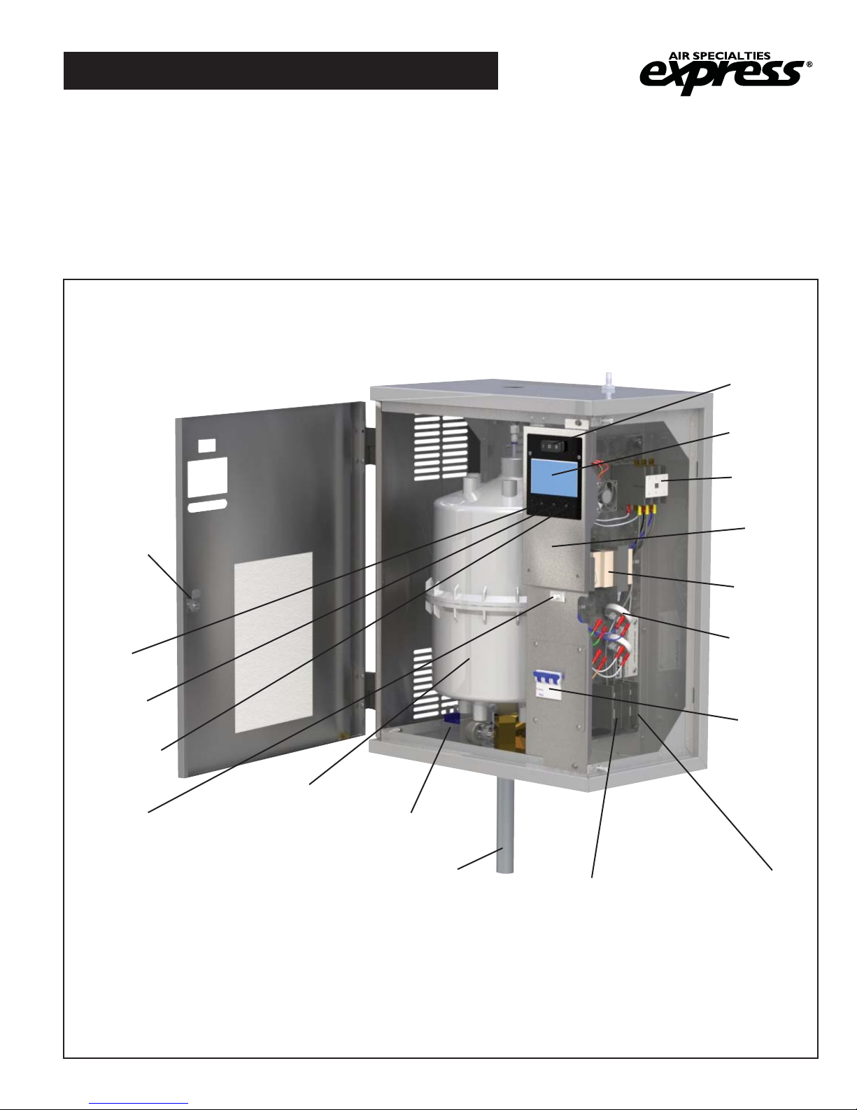
ASX “H” SERIES HUMIDIFIER
On-Off-Drain
Switch
True
Touchscreen
Contactor
Door Lock
Blue
Fill LED
Red
Drain LED
Orange High
Water LED
Door
Interlock
Switch
Cylinder
Drain Valve
Drain Pipe
Circuit
Board
(Behind Door)
Voltage
Transformer
Current
Transformers
Circuit
Breaker
(Optional)
Ground Lug
Distributor
Block
Photo A
(Model HTGH Shown)
FORM ASX-16834-I
ISSUED: 08-16
1
Page 2

TABLE OF CONTENTS
Introduction - Cautions .......................................................................................................3
Models ................................................................................................................................4
Installation ...................................................................................................................... 5-9
Electrical Data Sheet and Definition ............................................................................10-12
Humidifier Component Listing - Combo Unit HT/SAH, HT/SDH & HT/SGH .................... 13
Controls .......................................................................................................................14-19
Operation .......................................................................................................................... 20
True Touchscreen - Displays and Internal Control .....................................................21-27
Humidifier Mandatory Pre-startup Checklist ..................................................................... 28
Humidifier Startup Checklist .............................................................................................29
Humidifier Startup and Operations ................................................................................... 30
Fan Distribution Units ..................................................................................................31-32
Distribution Pipes.............................................................................................................. 33
Short Absorption Manifold ...........................................................................................34-35
Troubleshooting - Symptom, Cause and Action .........................................................36-41
Humidifier Operational Specifications ..............................................................................42
Humidifier Maintenance Checklist .................................................................................... 43
Preventative Maintenance ............................................................................................... 44
Extended Shutdown/Starting After Extended Shutdown .................................................. 45
Replacement Cylinder ......................................................................................................46
Removing the Cylinder ..................................................................................................... 47
Installing the Cylinder .......................................................................................................48
Replacement Cylinder Order Form .................................................................................. 49
Replacement Parts ......................................................................................................50-53
Warranty ...........................................................................................................................54
2
Page 3
INTRODUCTION
CAUTIONS
CAUTION! DO NOT INSTALL, USE OR OPERATE THIS EQUIPMENT UNTIL THIS
MANUAL HAS BEEN READ AND UNDERSTOOD. READ AND SAVE THESE INSTRUCTIONS FOR FUTURE USE.
CAUTION — Perform all basic safety steps before starting unit.
1. Proper mounting of unit cabinet to wall as described in following pages.
2. Make sure voltage and phase supply matches that of Product Identification Label located on left side of unit
cabinet and located on back plane in electrical section.
3. Qualified installers should be used for electrical and plumbing installation, being aware of all current and
corresponding codes.
WARNING: HOT SURFACES — Water/Steam and Distribution Methods
The process of humidification, using an electrode style humidifier, creates steam through the boiling process.
Temperatures of this boiling water and steam can reach 212°F (100°C). This system in turn, creates extremely hot
surfaces (cylinder surface, steam hose, steam pipe, condensate hose/pipe, distribution piping) and hot water or
visible/non-visible steam. Even discharged condensate water can be extremely hot. Contact with these surfaces
water or steam can cause personal injury. To avoid severe burns, always proceed with extreme caution. Before any
service or maintenance is performed, turn off unit, disconnect electrical service and allow humidifier unit to cool down
completely.
WARNING — De-energize Electrical Supply
Before any service or maintenance is performed make sure main power supply is disconnected and safety labeled
(If Carnes unit is set up with a built-in circuit breaker, turn off circuit breaker and additionally turn off main power
supply breaker). Failure to turn off main power supply could result in fire, electrical shock or both, resulting in damage
to property, personal injury or death.
CAUTION
Follow all recommendations, instructions and precautions in this Installation, Operation and Maintenance Manual to
maximize performance, maintain efficiency and to provide a safe operational environment.
Liability:
Carnes does not accept any liability for installations of humidifier equipment installed by unqualified personnel or the use
of parts, components, equipment or alterations of Carnes manufactured equipment that is not authorized or approved by
Carnes.
3
Page 4
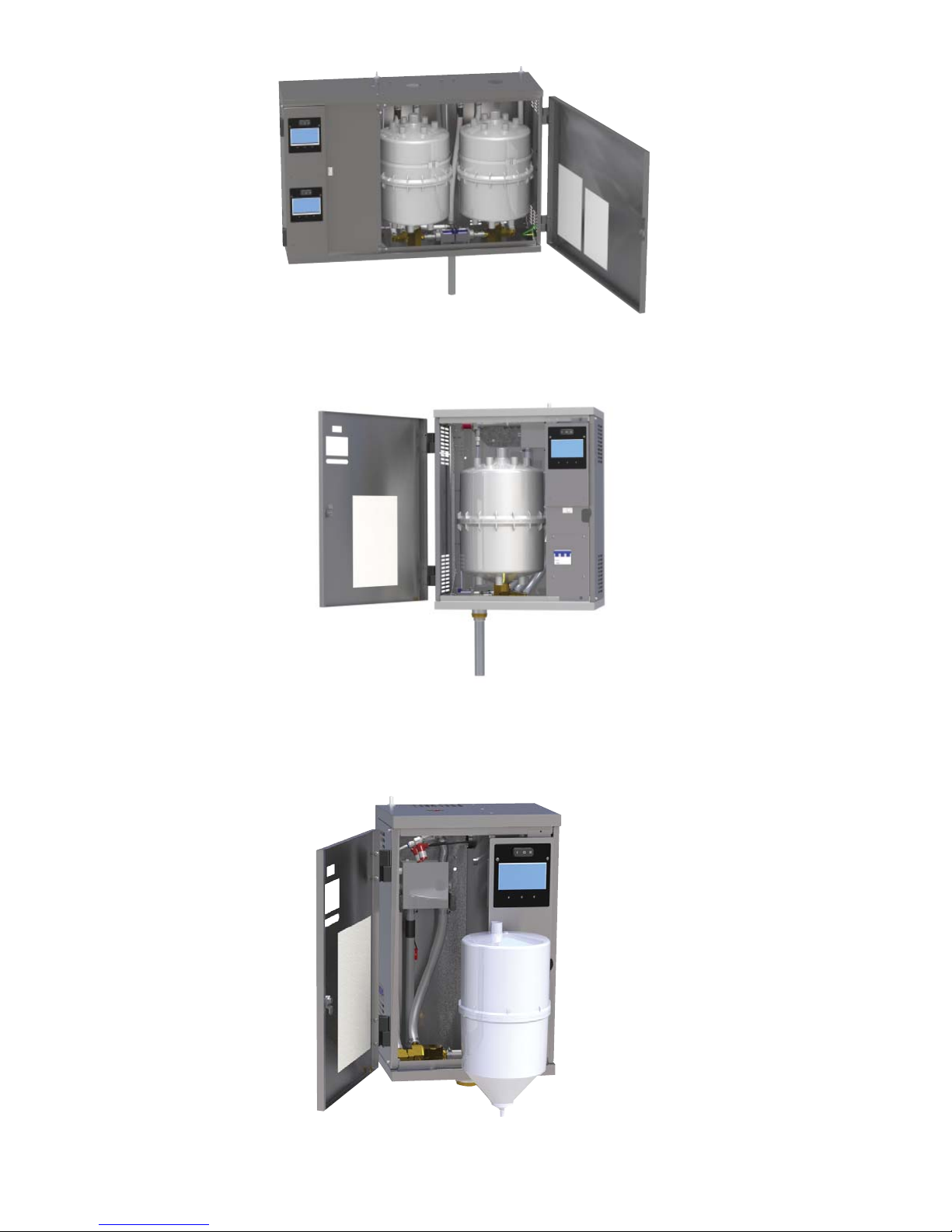
HSHH
HTGH / HSAH / HSDH
HRAB
4
Page 5
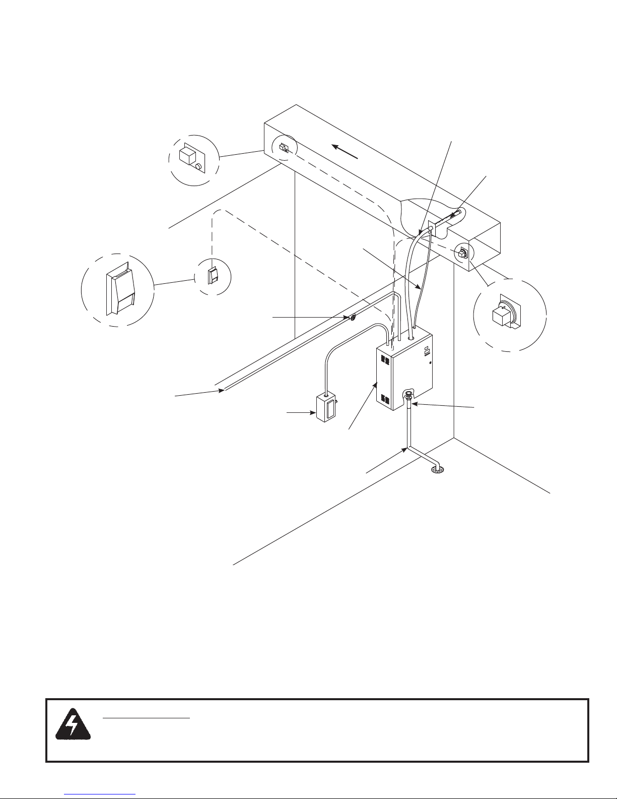
TYPICAL INSTALLATION
Figure A
Wall Humidistat
Cold Water Line
(Comes into the
bottom of the
humidifier)
High Limit
Humidistat
Water Shutoff
Valve (By Others)
Fused Disconnect
or Circuit Breaker
(By Others)
Steam
Hose
Air Flow
Steam Distributor
Pipe
Condensate
Return Line
Air Flow Switch
Air Gap
Drain Fitting
Humidifier
Cabinet
Drain Line
WARNING:
THE HUMIDIFIER CABINET CONTAINS HIGH VOLTAGE WIRING AND HOT
SURFACES. THE CABINET DOOR INCLUDES A LOCK AND ACCESS MUST BE LIMITED TO
TRAINED AND QUALIFIED PERSONNEL ONLY. THE DOOR MUST BE LOCKED AND KEY MUST
BE KEPT IN A SECURE LOCATION AWAY FROM THE HUMIDIFIER.
5
Page 6
INSTALLATION
UNPACKING AND INSPECTION
1. Inside the cabinet is an envelope containing the
following items:
A. Keys to the humidifier cabinet
B. Steam hose clamps
C. Condensate return line clamps
D. Drain pipe fitting
E. Installation, operation and maintenance manual,
yellow caution sheet for hose routing, replacement
parts list and spec sheet
F. Keys to unlock the humidifier cabinet
2. Open the cabinet and check for concealed shipping
damage. Report any damage immediately to the carrier
who delivered the shipment.
3. The following components are packed in a shipping
carton for connection when installing the humidifier.
A. Distribution pipe
B. Steam hose
C. Condenstate return line
4. Optional accessories may be packed with the cabinet
or in the same shipping carton. Large accessories may
ship in separate cartons.
MOUNTING THE HUMIDIFIER
Locate the humidifier cabinet level and plumb, using
the level screws (Photo B) on a surface as close to the
steam distributor as possible at a convenient height for
servicing. Allow 12” or more on each side for panel access
and 16” from the bottom of the unit to floor to allow for drain
connections. If there is no common drain within close
proximity of humidifier, a drain pump (Carnes HXWA) may
be required to accommodate this distance. Allow 18” in
front of single cylinder cabinets and 38” for dual cylinder
cabinets to allow for opening and removal of the cabinet
door.
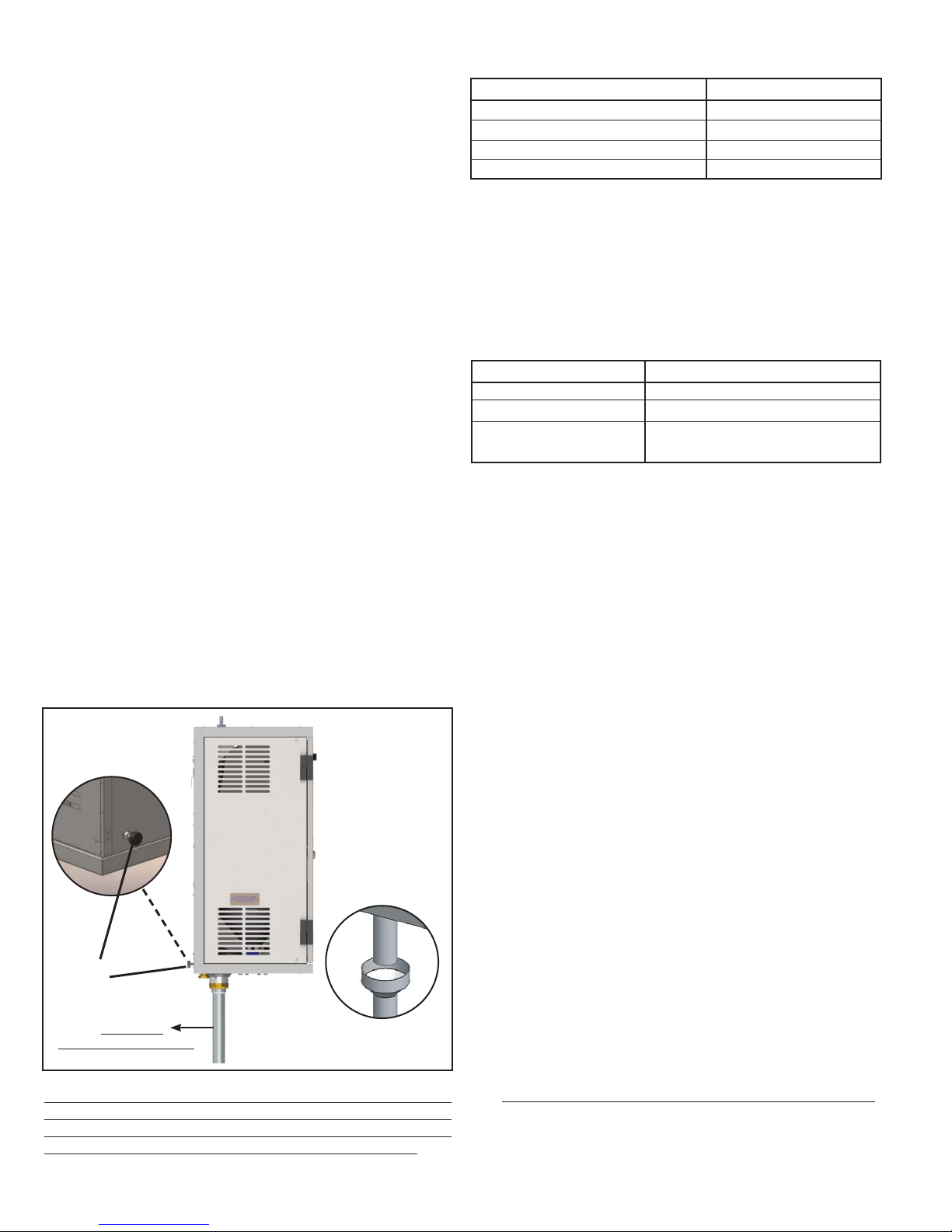
Photo B
An air gap fitting
must be included
in drain plumbing
setup (non-Carnes
installation).
See picture:
Table 1 - MAXIMUM OPERATING WEIGHT
Model Pounds
H_AH 61
H_DH 72
H_GH 110
H_HH 203
Fasten the mounting bracket to wood studs or solid wood
using fasteners shown in fastener recommendation below.
Place the mounting flange on the humidifier cabinet over
the mounting bracket. A sheet metal screw should be
installed through the back of the humidifier cabinet to
secure the humidifier to the mounting bracket. Fasteners
are not provided by Carnes.
Table 2 - FASTENER RECOMMENDATION*
*1/4” Lag Screw, 1” Minimum Length
Model Fasteners Required
H_AH 4
H_DH 4
H_GH 4
H_HH 6
SUPPLY WATER CONNECTION
A 3/8” FPT fitting is provided at the bottom of the humidifier
for connection to tap water supply (top of the humidifier for
HRAA). A shutoff valve, not provided by Carnes, must be
installed just ahead of this fitting.
SUPPLY WATER GUIDELINES
Use ordinary cold tap water (20 to 120 psi) - DO NOT use
hot water, DI (deionized water), RO (reverse osmosis)
water. Using mechanically softened water, or tap water
with conductivity over 800 Micromhos is not recommended. Supply water quality is a very important factor
on how a humidifier functions and how often it will need to
be maintained. There are many substances in untreated
water. When water is boiled into steam, it creates a scale
build-up that is left behind in the cylinder. These substances
left behind continue to change the properties of the supply
water. Having corrosive supply water can decrease the
service life of the humidifier and the cylinder. Also using
excessively hard supply water can increase maintenance
requirements. It’s recommended using a water supply that
has a total water hardness between 50-120 (ppm) parts per
million. Corrosion caused by high amounts of chlorides or
other corrosive substances in the supply water can cause
damage and rapid corrosion to the cylinders electrodes and
humidifier. It’s recommended using a water supply that has
< 50 ppm of measured chlorides.
Leveling
Screws
NOTE: Drain Pipe
is NOT an air gap fitting.
Call Carnes to
purchase an air gap.
(P/N 690-0176)
The humidifier must never be located outside or where it
may be exposed to freezing temperatures unless a heated,
ventilated weather proof enclosure by others is provided.
Do not mount humidifiers on a hot or vibrating surface.
DRAIN LINE CONNECTION
1. Locate the drain pipe fitting in the accessory bag
included with the unit. Have proper tooling available to
attach the drain pipe.
2. Connect the drain pipe fitting to the cabinet drain hole
on the bottom of the unit (Refer to Photo B).
3. Connect the drain pipe fitting to an S or P trap. Use
plumbing material capable of handling hot water.
Include a 1” air gap fitting as part of the drain plumbing.
See Photo B.
Note: If the drain water pump accessory package is
used, follow instructions included with the drain water
pump package.
6
Page 7
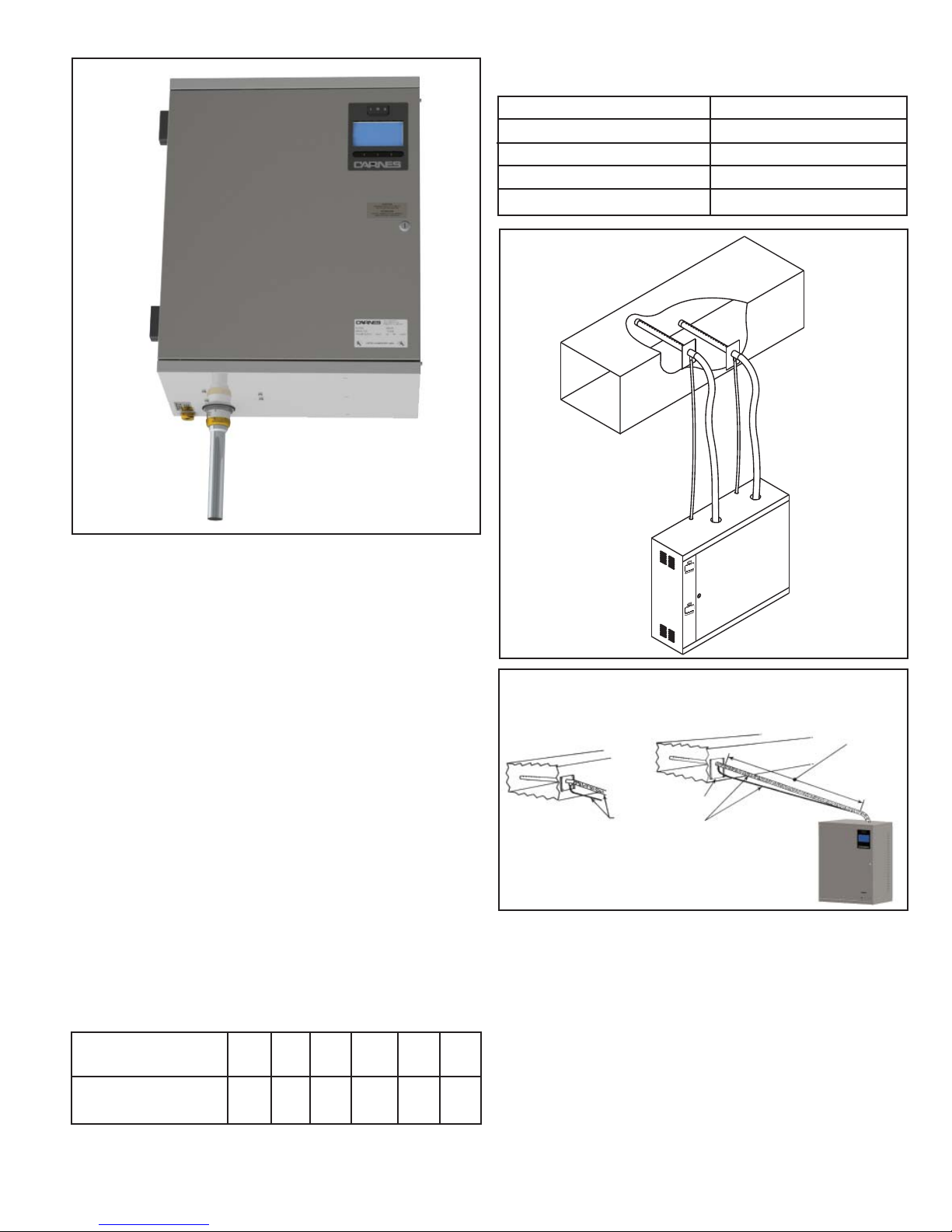
Photo C
Outer diameter of drain pipe is 1-1/4”.
Air gap fitting must be added.
AFFECT ON CAPACITY DETERMINED BY STEAM HOSE
LENGTH
(Table 3-A)
Distance Loss
10 Ft. 1.0 lb./hr.
20 Ft. 2.0 lb./hr.
25 Ft. 2.5 lb./hr.
40 Ft. 4.0 lb./hr.
Figure B
STEAM DISTRIBUTOR PIPE LOCATION
It is critical to provide proper routing of flexible
hose and hard tubing to maximize efficiency and
effectiveness. See Figure B-E. Not following the
instructions in this Installation, Operation, and
Maintenance Manual could void all warranties, unless
you have consulted with the factory and have prior
written approval. Each steam cylinder requires a separate
distributor pipe, steam hose, and condensate return line. A
cylinder may supply more than one distributor pipe by using an
accessory “T” fitting but the output cannot be controlled
separately. In a typical installation the humidifier is located
below the duct as shown in Figure A. The distance between
the humidifier cabinet and the steam distributor pipe
should be the minimum distance possible. Refer to
Table 3 for maximum length that may be installed based
on duct static pressure and pound output. Under less than
perfect conditions, (installation issues, routing problems for
steam and condensate return hose, and extreme steam
hose lengths) it is possible to lose significant amounts of
output. The use of 90° elbows add approximately three
feet of equivalent length when hard tubing is used, thus
negatively affecting capacity, efficiency, and can cause
back pressure issues and cylinder arching.
MAXIMUM STEAM HOSE LENGTH (Table 3)
Duct Static
Pressure “wg”
Maximum Steam
0 1 2 3 4 5
40 35 30 25 15 10
Hose Length (Ft.)
For a residential unit (HRAB) the maximum length of steam
hose that may be installed is 10 feet.
TYPICAL HOSE LOCATION
FOR LENGTHS UP TO
12 FEET
Mounting plate
must be plumb.
Condensate hoses
must pitch down
continuously to humidifier
— NO pockets, sags
or horizontal runs.
If hose is difficult to
support within this
length, straight
copper tube should
be used and
insulation applied.
Figure B-1
The maximum length of steam hose that may be installed
as shown in Figure B & B-1 is 12 feet. For a steam hose
length over 12 feet refer to Figure D. A drain “T” must be
used to remove condensation that occurs in steam hose
lengths over 12 feet. It is preferable to have the steam hose
rise vertically from the cabinet and then slope downward
to the distributor pipe as shown. If sufficient headroom
is not available it is possible to install with an upward
slope but the rise should be 2” in 12” to allow for proper
condensate drainage and steam flow. Carnes electrode steam
humidifiers are non-pressurized, maximum of 1/2 psi. Every
application is different. Hose lengths for small capacity units
will be considerably shorter than larger units. All variables
must be taken into consideration.
7
Page 8
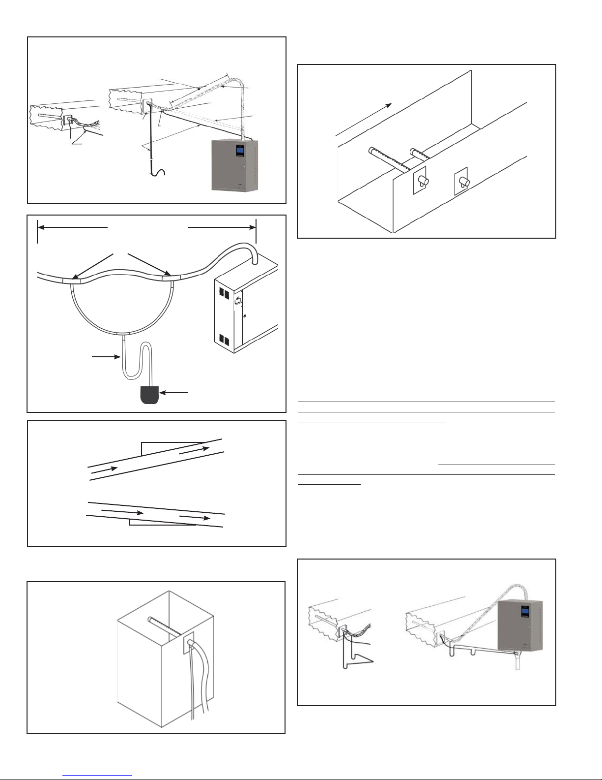
HOSE LOCATION
FOR RUNS FROM
12 FEET TO 40 FEET
Condensate hoses
must pitch down
continuously to
humidifier — NO pockets,
sags or horizontal runs.
Figure C
When hose is difficult to support
within this length, straight
copper tube should be used
and insulation applied.
Mounting
plate must
be plumb.
To Drain
Drain Tee
Trap, if
condensate
routes to drain.
Extended Length
Steam line
must pitch
down toward
drain tee —
NO pockets,
sags or
horizontal
runs.
Optional if
sufficient
head room
is not
available.
If multiple pipes are used they should be staggered as shown in
Figure G.
Figure G
Air Flow
Condensate
Trap
Figure D
Figure E
12”
Common Drain
2”
Steam
Steam
.5”
12”
In a vertical duct with either upward or downward air flow the
distributor pipe should be installed horizontally as shown in
Figure F.
Figure F
STEAM DISTRIBUTOR PIPE LOCATION (Continued)
Steam distributor pipes must be located on a plumb surface so
condensate that forms will run back into the return line. The pipe
should be located in the center of the duct to insure distribution
of steam into the airstream. A minimum clearance of 4” must be
maintained between the top of the duct and the distributor pipe.
The steam distributor pipes are usually located in the supply duct
downstream of the fan. When installed in packaged units the
distributor should be mounted just downstream of the fan
discharge.
It is important to locate the distributor pipe as far upstream as
possible from any obstructions in the ductwork so that moisture
can be absored before it contacts a surface and accumulates.
There must be a minimum of six feet between the distributor and
any fans, coils, filters, dampers, elbows, or outlets downstream to
reduce the possibility of condensation.
It may be possible to minimize the absorption distance by using
multiple distributor pipes, or for extremely short absorption
distances, a manifold may be required (See Short Absorption
Manifold Section in this manual). Duct air temperatures below
60°F may require a condensate drain pan below the steam
distributor pipe. Always avoid locating the distribution pipe
upstream from any insulation in the duct as excess moisture may
cause damage.
The distributor pipe may be located below the humidifier if the
installation is made in accordance with Figure H. A trap may
be necessary to prevent steam from flowing back through the
condensate return line.
HOSE LOCATION
WHEN DUCT IS LOWER
THAN HUMIDIFIER
Mounting
plate must
be plumb.
8
Trap to
common
drain.
Figure H
Condensate hoses
must pitch down
continuously to humidifier or common drain —
NO pockets, sags or
horizontal runs.
Drain Tee
Water trap required
to prevent live steam
from returning.
Page 9
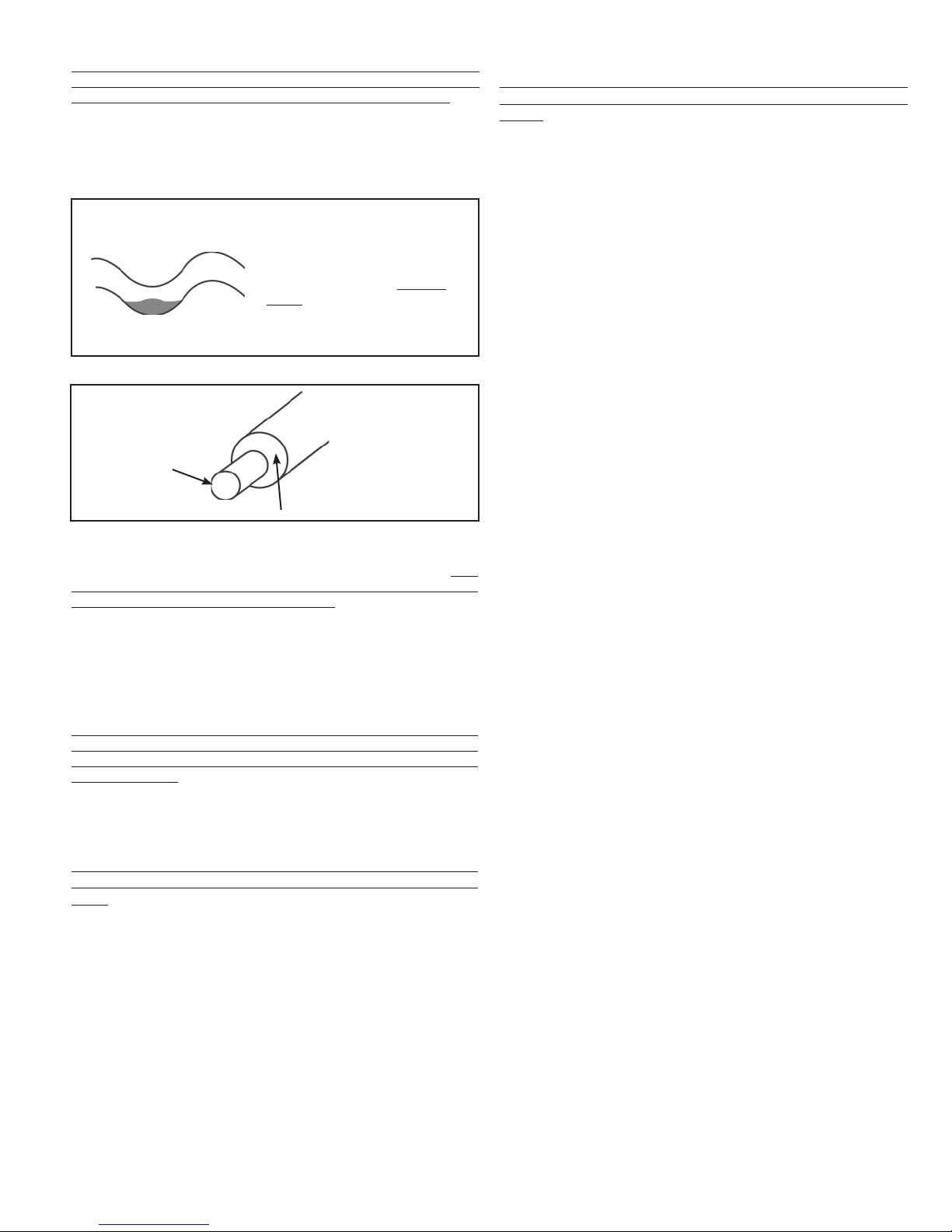
It is very important that both the steam hose and condensate
return line, whether flexible or hard tubing, be installed so
there are no sags, low points, dips, or horizontal runs. The
steam is at a very low pressure and it cannot overcome any
resistance caused by accumulating water standing in the steam
hose. Accumulation in the condensate return hose will hamper the
flow and may cause water to back up into the duct.
Figure I
Exaggerated for emphasis.
Note: Over time and extended
heat, the situations described
in the previous paragraph
can occur. That’s why it is
important to perform monthly
visual inspections to maintain
and correct, improper routing of
steam and condensate lines.
Figure J
Steam Pipe
1” Minimum Pipe Insulation
If it is difficult to install the steam hose to prevent sags, it is
recommended that a copper tube be used as a substitute. If a
copper tube is used, a minimum of one inch of insulation must be
applied to prevent excessive condensation (See Figure J). A short
length of steam hose must be used to connect the cylinder in the
humidifier to the copper tube and another short length to connect
the copper tube to the distributor pipe. Size 3/4” copper tube (with
7/8” steam hose) can be used with steam cylinders having output
rates up to 30 pounds per hour. Size 1-1/2” copper tube (with
1-5/8” steam hose) should be used with steam cylinders having
output rates over 30 pounds per hour.
Hose lengths of no longer then 10-20 feet and proper inclines or
routing, as expressed in this manual, will provide the best chance
of having a proper operating humidifier with efficient and effective
steam dispersion.
STEAM DISTRIBUTOR PIPE INSTALL
EACH CYLINDER REQUIRES SEPARATE STEAM HOSE,
CONDENSATE RETURN LINE, AND STEAM DISTRIBUTOR
PIPE.
1. The steam distributor pipe must be mounted on a plumb
surface and inclined upward. This is required so the
condensate which forms in the distributor pipe will drain to the
return line and back to the unit, or to a common drain.
2. Insert distributor pipe into duct and secure with four sheet
metal screws (not included).
3. Special distributor pipes are shipped with specific instructions
on how to mount them.
4. If the optional fan distribution unit is to be used, follow the
instructions included with the unit.
CONNECT THE STEAM HOSE
COPPER OR BRASS TUBE IS THE ONLY ACCEPTABLE
SUBSTITUTE FOR CARNES STEAM HOSE OR CONDENSATE
HOSE.
1. The steam hose should be installed so there is a continuous
rise from the humidifier to the distributor pipe. Support the
steam hose at intermediate points to prevent dips, pockets,
sags, or horizontal runs. See Figure I.
2. Any turns should have a minimum radius of 8” to prevent the
hose from kinking. Fasten the steam hose to the distributor
pipe with one of the hose clamps provided.
3. Push the steam hose through the opening on the top of the
humidifier cabinet and slip it over the outlet stub on the top of
the cylinder. Fasten with the hose clamp provided.
4. If long lengths of steam hose or hard tubing are used, the
use of periodic “T’s” to drain condensate should be used.
See Figure D.
CONDENSATE RETURN LINE
1. Fasten the condensate return line to the distributor pipe with
the hose clamp provided.
2. Follow the steam hose to the humidifier cabinet and secure
the return line to the steam hose.
3. Connect the return line to the condensate return inlet with a
hose clamp provided.
4. If it is impossible to maintain a drop to the top of the cabinet,
it is necessary to run the condensate return line directly to the
air gap drain fitting or some other drain.
5. A trap of sufficient size may be necessary to prevent loss of
steam through the return line and reduce the temperature of
condensate water to the common drain. Do not install a trap if
condensate is returned to the top of the cabinet.
STEAM DISPERSION CRITERIA
1. Distributor pipe location must be at a minimum of 6 feet
upstream from any elbows, splits, coils, turning vanes, grilles,
diffusers, etc.
2. If duct temperature is 60°F or less, 10 feet is recommended.
3. Under normal conditions, most absorption distances will be
approximately 4 to 5 feet.
4. If distance recommended is not possible, then a drain pan
may be required.
5. If the air in the duct cannot accommodate the steam output,
the only recourse may be to lower the maximum output of the
unit.
6. If shorter absorption distances are required, 3 feet or less,
multiple distributor pipes could be used. Two pipes split off
one steam hose or two pipes from a dual cylinder unit.
7. If even shorter absorption distances are required, 2 feet
or less, then multi tube short absorption manifolds may be
required.
It is important to keep in mind that there are a lot of variables
involved in proper steam distribution and absorption distances
such as duct length downstream from the dispersion method,
required absorption distance determined by design, capacity of
humidification, velocity of air flow, temperature of air flow, location
of humidifiers, distance between humidifiers to distribution point,
and so on. Proper planning is a prerequisite to good performance.
9
Page 10
ELECTRICAL CONNECTIONS
WARNING: BEFORE MAKING ANY ELECTRICAL
CONNECTIONS SWITCH POWER OFF AT SERVICE
PANEL, FUSED DISCONNECT OR CIRCUIT
BREAKER AND LOCK THE DISCONNECTING
MEANS TO PREVENT POWER FROM BEING
SWITCHED ON ACCIDENTALLY.
POWER MUST BE OFF BEFORE MAKING ANY ELECTRICAL
CONNECTIONS.
Check unit electrical characteristics on the label on the outside
of the cabinet. The power provided must be the same as what
is described on the label. If it does not, contact your Carnes
Representative. All local and national codes must be followed
when connecting power to the unit.
A fused disconnect or circuit breaker, not provided by Carnes,
MUST be installed per local and national codes. See Table 4 for
recommended circuit ratings. The optional circuit breaker switch
installed in the humidifier is NOT for use as a replacement for
the required external disconnect switch but as a maintenance
convenience.
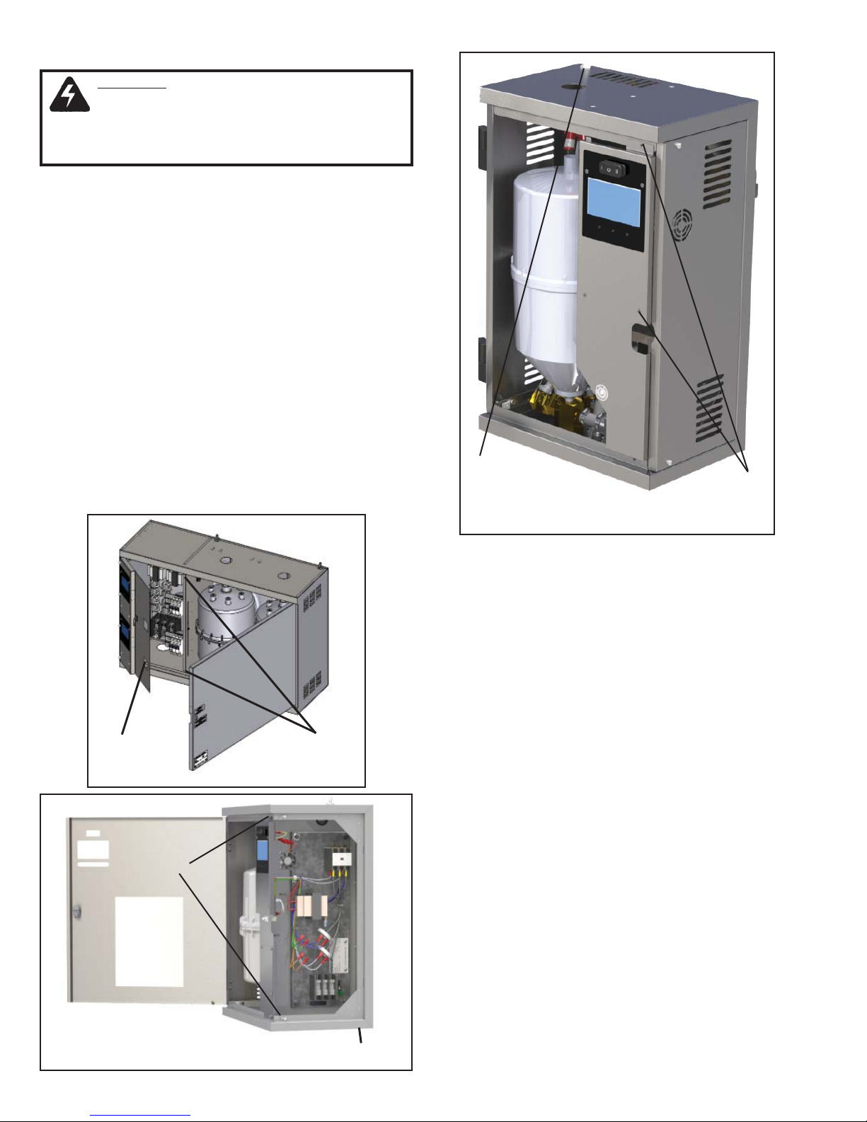
1. Remove screws securing hinged panel for access to wiring.
See Photos D, E and F for different electrical locations.
2. An opening is provided on the bottom of the electrical
section. Bring electrical power lines through this opening and
connect to electric power terminals.
3. Connect cabinet ground terminals to an independent ground.
DO NOT use the neutral of a four-wire power supply.
4. Replace electrical cover panel.
HTHH
Incoming
Electrical
Screws
Residential Humidifier
Photo F
Incoming
Electrical
Screws
Photo D
Screws
ELECTRICAL DATA SHEET DEFINITIONS
1. Optional Circuit Breaker designates the quantity and amp
rating of optional factory installed circuit breakers. Circuit
breakers are available in models with an ‘HT
’
prefix. All
models over 48 amps have internal circuit breakers factory
installed.
2. Maximum Lb./Hr. designates maximum capacity of the
humidifier. Units are shipped from the factory preset at the
maximum rate. The output rate may be easily reset after
installation anywhere between 100% and 20% of maximum
capacity.
3. Voltage and Phase designates available phase and nominal
voltages. Single phase units may be operated from two legs
of a three phase supply but the load will be unbalanced.
4. kW is the power rating of the maximum output rate of the
humidifier. If a unit’s max output is adjusted lower, the kW is
reduced proportionally.
5. Line Amp and Disc. Size are amp ratings shown for use in
selecting electrical service requirements.
6. Steam Cylinder shows the quantity and model of steam
generating cylinders mounted inside the humidifier. Each
cylinder requires its own steam distribution pipe, steam hose,
and condensate return line.
7. Cylinder Wire Current is the current a single cylinder wire
should be carrying for a given unit at max output. This does
not include ‘dummy’ electrode wires that never carry any
current, i.e. humidifiers with C65 cylinders and single phase
humidifiers not using AX cylinders.
(H_AH) (H_DH) (H_GH)
Humidifiers
Photo E
Incoming
Electrical
10
Page 11
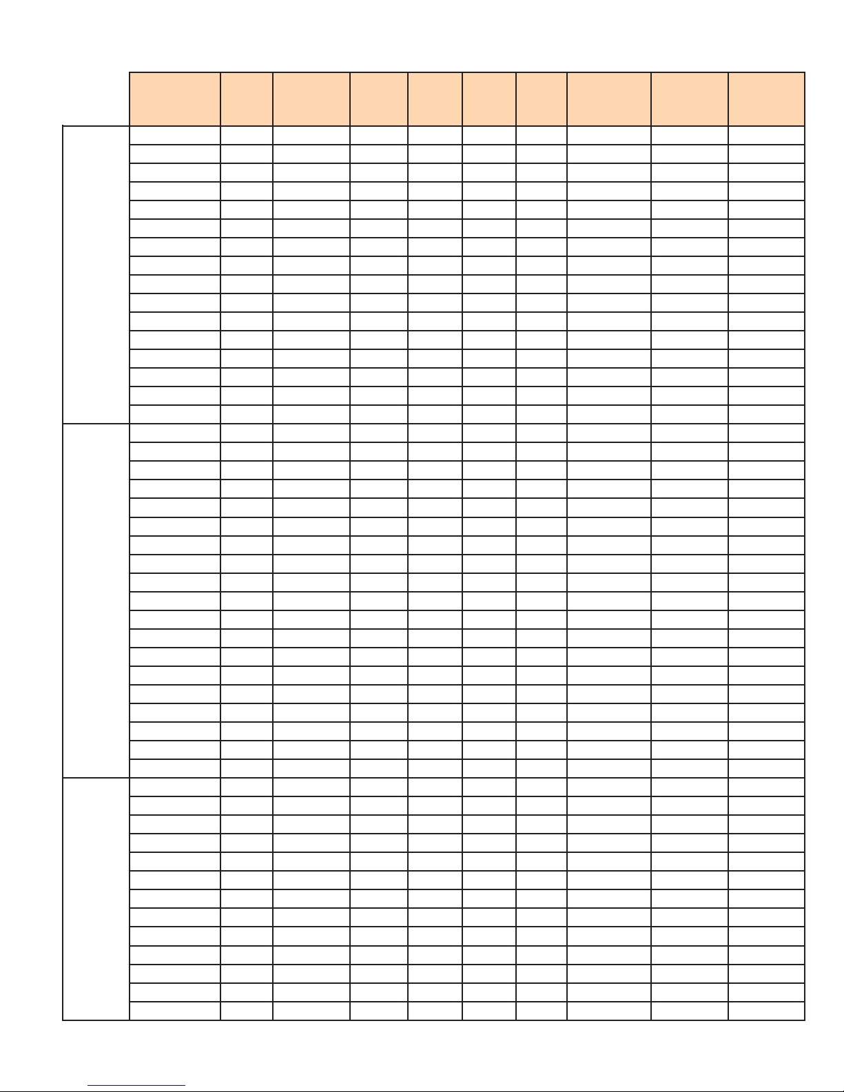
ELECTRICAL DATA AND UNIT DETAIL SHEET - Table 4
HSAH
HTAH
HSDH
HTDH
HSGH
HTGH
Max
Model
H_AHAU 5 120 1 1.725 14.4 25 1-20 Amp AX220 14.4
H_AHBU 5 208 1 1.725 8.3 15 1-15 Amp AX380 8.3
H_AHDU 5 230 1 1.725 7.5 15 1-20 Amp AX380 7.5
H_AHFU 5 277 1 1.725 6.2 15 1-15 Amp AX380 6.2
H_AHLU 5 380 1 1.725 4.5 15 1-15 Amp AX600 4.5
H_AHQU 5 415 1 1.725 4.2 15 1-15 Amp AX600 4.2
H_AHMU 5 460 1 1.725 3.7 15 1-15 Amp AX700 3.7
H_AHNU 5 575 1 1.725 3.0 15 1-15 Amp AX700 3
H_AHAU 10 120 1 3.45 28.7 45 1-40 Amp AX220 28.7
H_AHBU 10 208 1 3.45 16.6 25 1-25 Amp AX380 16.6
H_AHDU 10 230 1 3.45 15.0 25 1-25 Amp AX380 15
H_AHFU 10 277 1 3.45 12.4 20 1-20 Amp AX380 12.4
H_AHLU 10 380 1 3.45 9.1 15 1-15 Amp AX600 9.1
H_AHQU 10 415 1 3.45 8.3 15 1-15 Amp AX600 8.3
H_AHMU 10 460 1 3.45 7.5 15 1-15 Amp AX700 7.5
H_AHNU 10 575 1 3.45 6.0 15 1-15 Amp AX700 6
H_DHBU 20 208 1 6.9 33.1 50 1-45 Amp B380 33.1
H_DHDU 20 230 1 6.9 29.9 45 1-40 Amp B380 30
H_DHFU 20 277 1 6.9 24.9 40 1-35 Amp B380 24.9
H_DHLU 20 380 1 6.9 18.1 30 1-30 Amp B600 18.1
H_DHQU 20 415 1 6.9 16.6 25 1-25 Amp B600 16.6
H_DHMU 20 460 1 6.9 15.0 25 1-25 Amp B700 15
H_DHNU 20 575 1 6.9 12.0 20 1-15 Amp B700 12
H_DHCU 20 208 3 6.9 19.1 30 1-25 Amp B500 19.1
H_DHEU 20 230 3 6.9 17.3 30 1-25 Amp B500 17.3
H_DHTU 20 380 3 6.9 10.4 20 1-20 Amp B600 10.4
H_DHWU 20 415 3 6.9 9.6 20 1-20 Amp B600 9.6
H_DHGU 20 460 3 6.9 8.6 15 1-15 Amp B700 8.6
H_DHHU 20 575 3 6.9 6.9 15 1-15 Amp B700 6.9
H_DHCU 30 208 3 10.3 28.7 45 1-40 Amp B500 28.7
H_DHEU 30 230 3 10.3 25.9 40 1-35 Amp B500 25.9
H_DHTU 30 380 3 10.3 15.6 25 1-25 Amp B600 15.6
H_DHWU 30 415 3 10.3 14.4 25 1-25 Amp B600 14.4
H_DHGU 30 460 3 10.3 13.0 20 1-20 Amp B700 13
H_DHHU 30 575 3 10.3 10.4 20 1-15 Amp B700 10.4
H_GHBU
H_GHDU 30 230 1 10.3 44.9 70 1-60 Amp C62 22.4
H_GHFU 30 277 1 10.3 37.3 60 1-50 Amp C62 18.6
H_GHLU 30 380 1 10.3 27.2 45 1-40 Amp C62 13.6
H_GHQU 30 415 1 10.3 24.9 40 1-40 Amp C62 12.5
H_GHMU 30 460 1 10.3 22.5 35 1-30 Amp C62 11.3
H_GHNU 30 575 1 10.3 17.9 30 1-25 Amp C62 9.0
H_GHCU 40 208 3 13.8 38.3 60 1-60 Amp C62 19.1
H_GHEU 40 230 3 13.8 34.6 60 1-50 Amp C62 17.2
H_GHTU 40 380 3 13.8 20.9 35 1-35 Amp C65 20.9
H_GHWU 40 415 3 13.8 19.2 30 1-30 Amp C65 19.2
H_GHGU 40 460 3 13.8 17.3 30 1-25 Amp C65 17.3
H_GHHU 40 575 3 13.8 13.8 25 1-20 Amp C65 13.8
Lb/Hr Voltage Phase kW
* 30 208 1 10.3 49.7* 80 2-35 Amp* C62 24.8
Line
Amp
Disc.
Size
Optional
Circuit
Breaker*
Steam
Cylinder
Cyl Wire
Current
* = Circuit Breaker is REQUIRED per NEC 48 amp guideline.
11
Page 12
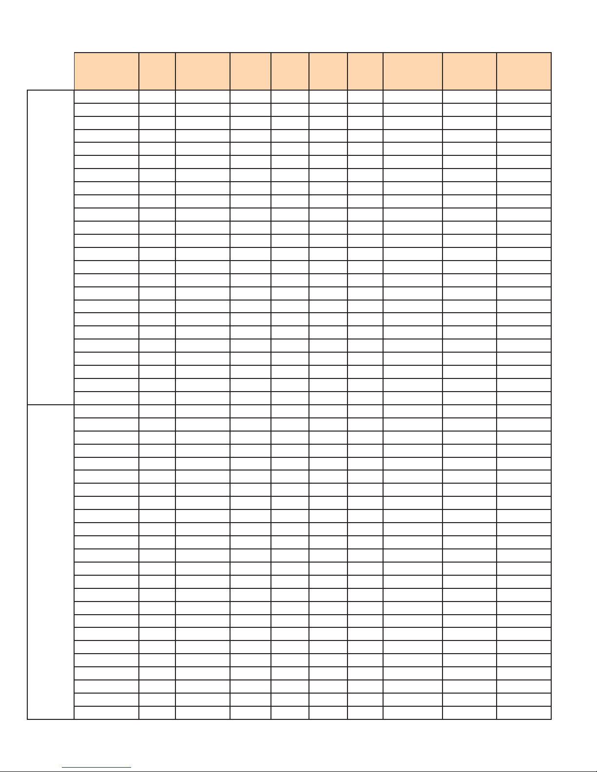
ELECTRICAL DATA AND UNIT DETAIL SHEET - Table 4 (continued)
HSGH
HTGH
HSHH
HTHH
Max
Model
H_GHCU 50 208 3 17.2 47.8 80 2-35 Amp C62 23.9
H_GHEU 50 230 3 17.2 43.2 70 1-60 Amp C62 21.6
H_GHTU 50 380 3 17.2 26.2 40 1-40 Amp C65 26.2
H_GHWU 50 415 3 17.2 24.0 40 1-40 Amp C65 24
H_GHGU 50 460 3 17.2 21.6 35 1-30 Amp C65 21.6
H_GHHU 50 575 3 17.2 17.3 30 1-25 Amp C65 17.3
H_GHCU
H_GHEU
H_GHTU 60 380 3 20.7 31.4 50 1-50 Amp C65 31.4
H_GHWU 60 415 3 20.7 28.8 45 1-45 Amp C65 28.8
H_GHGU 60 460 3 20.7 26.0 40 1-40 Amp C65 26
H_GHHU 60 575 3 20.7 20.8 35 1-30 Amp C65 20.8
H_GHCU
H_GHEU
H_GHTU 80 380 3 27.5 41.9 70 1-60 Amp C12 21
H_GHWU 80 415 3 27.5 38.4 60 1-60 Amp C12 19.2
H_GHGU 80 460 3 27.5 34.6 60 1-50 Amp C12 17.3
H_GHHU 80 575 3 27.5 27.7 45 1-40 Amp C12 13.9
H_GHCU
H_GHEU
H_GHTU
H_GHWU 100 415 3 34.4 47.9 80 2-40 Amp C12 24
H_GHGU 100 460 3 34.4 43.3 70 1-60 Amp C12 21.7
H_GHHU 100 575 3 34.4 34.6 60 1-50 Amp C12 17.3
H_HHCU
H_HHEU
H_HHTU
H_HHWU
H_HHGU
H_HHHU 125 575 3 43 43.2 70 2-30 Amp C12 (2) 10.8
H_HHCU
H_HHEU
H_HHTU
H_HHWU
H_HHGU
H_HHHU
H_HHCU
H_HHEU
H_HHTU
H_HHWU
H_HHGU
H_HHHU
H_HHCU
H_HHEU
H_HHTU
H_HHWU
H_HHGU
H_HHHU
Lb/Hr Voltage Phase kW
* 60 208 3 20.7 57.4* 90 2-40 Amp* C62 28.7
* 60 230 3 20.7 51.9* 80 2-40 Amp* C62 26
* 80 208 3 27.5 76.5* 125 2-60 Amp* C62 38.2
* 80 230 3 27.5 69.2* 110 2-50 Amp* C62 34.6
* 100 208 3 34.4 95.6* 150 2-60 Amp* C62 47.8
* 100 230 3 34.4 86.4* 150 2-60 Amp* C62 43.2
* 100 380 3 34.4 52.3* 110 2-50 Amp* C12 34.2
* 125 208 3 43 119.5* 200 4-40 Amp* C62 (2) 29.8
* 125 230 3 43 108* 175 4-40 Amp* C62 (2) 27
* 125 380 3 43 65.3* 100 2-50 Amp* C12 (2) 16.3
* 125 415 3 43 59.8* 90 2-45 Amp* C12 (2) 15
* 125 460 3 43 54.0* 90 2-40 Amp* C12 (2) 13.5
* 150 208 3 51.7 143.5* 225 4-50 Amp* C62 (2) 35.8
* 150 230 3 51.7 129.7* 200 4-50 Amp* C62 (2) 32.4
* 150 380 3 51.7 78.6* 125 2-60 Amp* C12 (2) 19.7
* 150 415 3 51.7 71.9* 110 2-60 Amp* C12 (2) 18
* 150 460 3 51.7 64.8* 100 2-50 Amp* C12 (2) 16.2
* 150 575 3 51.7 51.9* 80 2-35 Amp* C12 (2) 13
* 175 208 3 60.3 167.3* 300 4-60 Amp* C62 (2) 41.8
* 175 230 3 60.3 151.3* 250 4-60 Amp* C62 (2) 37.8
* 175 380 3 60.3 91.6* 150 4-35 Amp* C12 (2) 22.9
* 175 415 3 60.3 83.9* 150 2-60 Amp* C12 (2) 21
* 175 460 3 60.3 75.6* 125 2-60 Amp* C12 (2) 18.9
* 175 575 3 60.3 60.5* 100 2-50 Amp* C12 (2) 15.1
* 200 208 3 68.9 191.2* 300 4-60 Amp* C62 (2) 47.8
* 200 230 3 68.9 172.9* 300 4-60 Amp* C62 (2) 43.2
* 200 380 3 68.9 104.7* 175 4-40 Amp* C12 (2) 26.2
* 200 415 3 68.9 95.9* 150 4-35 Amp* C12 (2) 23.9
* 200 460 3 68.9 86.4* 150 2-60 Amp* C12 (2) 21.6
* 200 575 3 68.9 69.2* 110 2-50 Amp* C12 (2) 17.2
Line
Amp
Disc.
Size
Optional
Circuit
Breaker*
Steam
Cylinder
Cyl Wire
Current
* = Circuit Breaker is REQUIRED per NEC 48 amp guideline.
12
Page 13
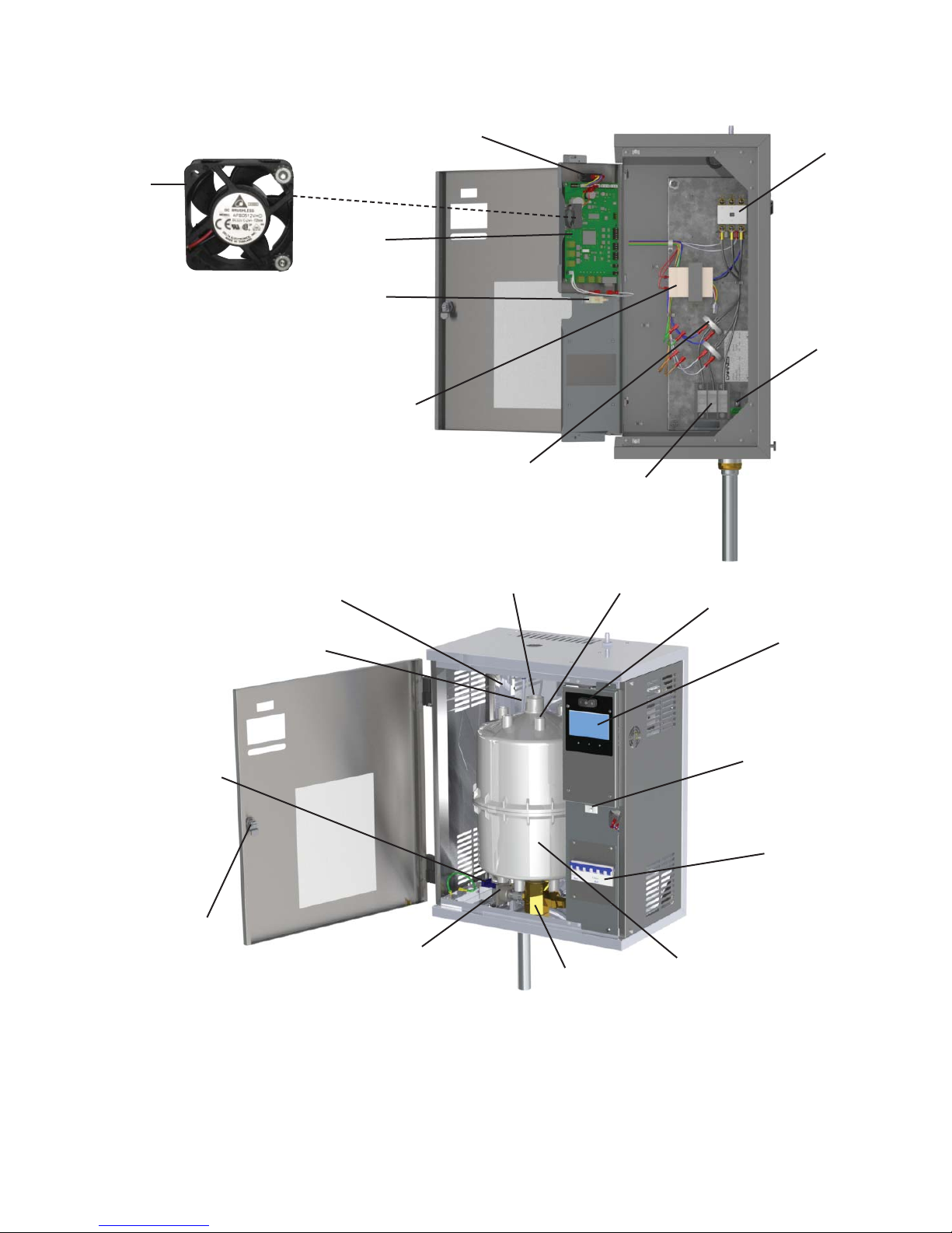
HUMIDIFIER COMPONENT LISTING -
Figure K
23
10
1
2
3
4
5
6
12
13
1
8
7
21
19
1. On-Off-Drain Switch
2. Circuit Board
3. Door Interlock Switch
4. Voltage Transformer
5. Current Transformer
6. Distribution Block
7. Ground Lug
8. Contactor
20
18
17
9. High Water Sensor (behind cylinder)
10. Fill Cup
11. Fill Valve (not shown)
12. Steam Hose
13. Electrode Connector
14. LCD - True Touchscreen
15. Circuit Breakers (Option)
16. Cylinder
14
3
15
16
17. Cylinder Fitting
18. Drain Valve
19. Lock
20. Water Inlet Hose
21. Water Inlet Fitting
22. Fill Valve Inlet Push - On Connector
(not shown)
23. Cooling Fan
13
Page 14
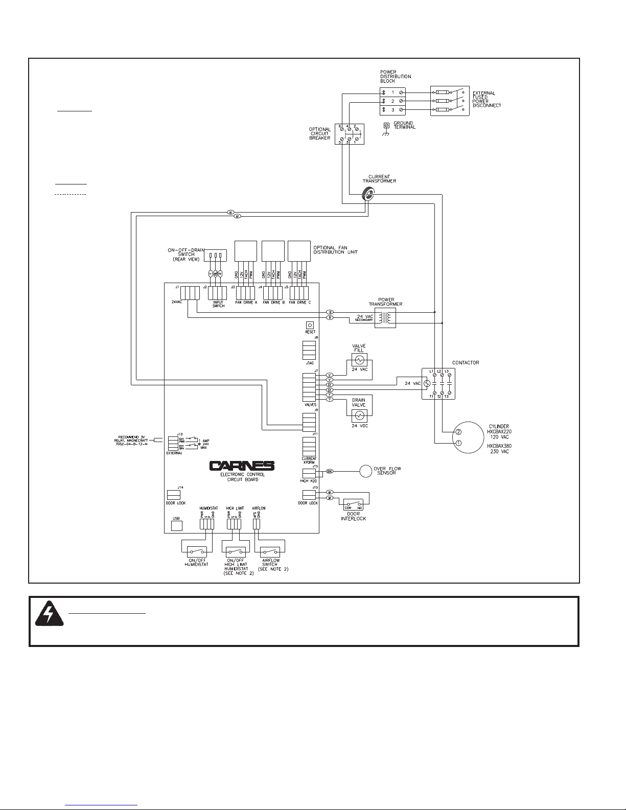
CONTROL CONNECTIONS -
NOTES:
1. Observe proper polarity when using
voltage or current measuring devices.
2. If air flow and high limit switches are
not used, a jumper must be installed.
Supplied By Carnes
Supplied By Others
Figure L
WARNING: BEFORE MAKING ANY ELECTRICAL CONNECTIONS SWITCH POWER OFF AT
SERVICE PANEL, FUSED DISCONNECT OR CIRCUIT BREAKER AND LOCK THE DISCONNECTING
MEANS TO PREVENT POWER FROM BEING SWITCHED ON ACCIDENTALLY.
1. A 7/8” opening is provided on top or bottom of the cabinet. The control wiring should pass through the opening to the
terminal strip.
NOTE: A built-in transformer provides power for the control circuit. No outside power supply is required for the control
circuit.
2. If an air flow switch or high limit humidistat is not used, jumpers must be installed before the humidifier will operate.
Controls should be connected to the terminals on the circuit board as shown in Figure L using #18 AWG wire.
Avoid running control wiring near high voltage wires.
14
Page 15
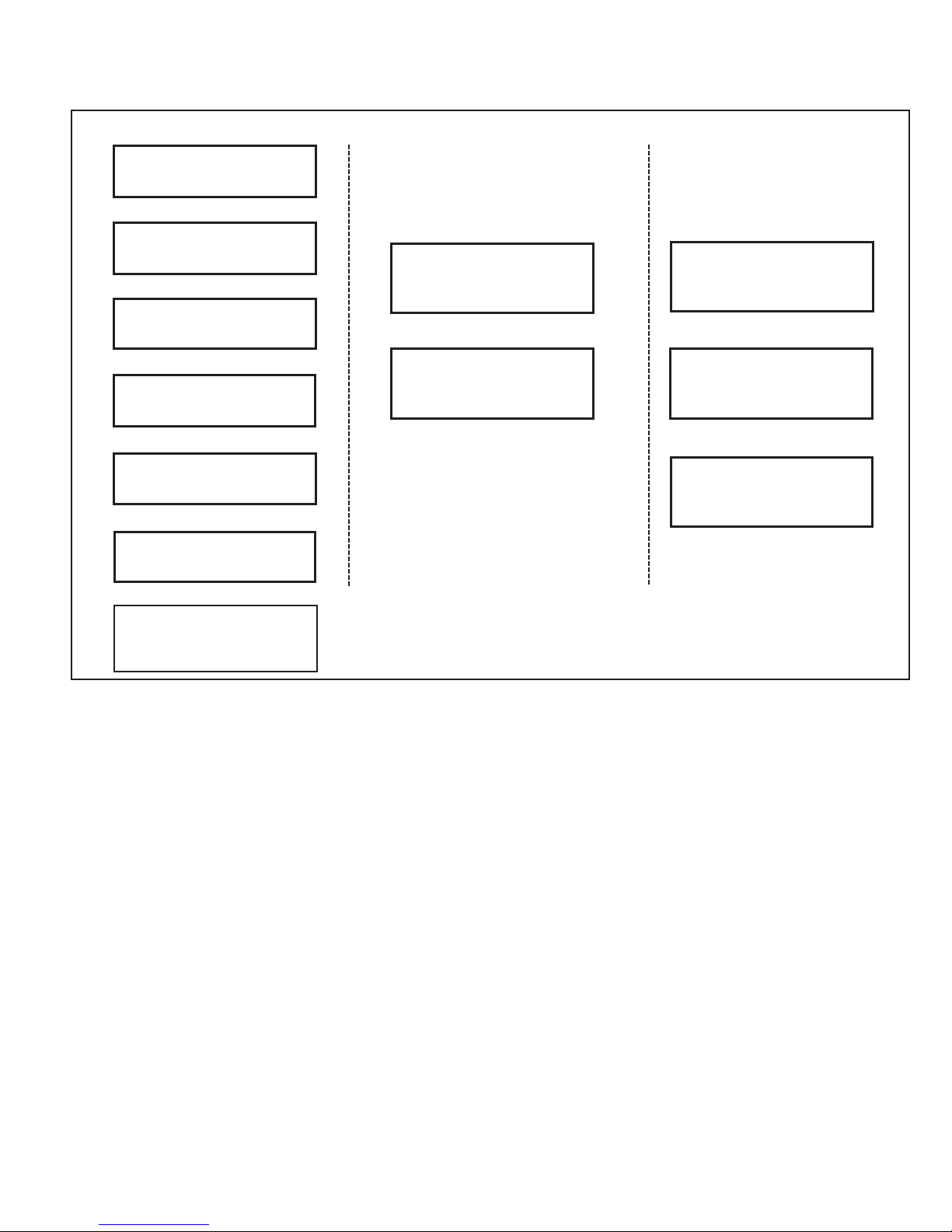
CONTROLS
CONTROL OPTIONS - Figure M
CONTROL HUMIDISTAT AIR FLOW DETECTION CONDENSATION
PROTECTION
WALL HUMIDISTAT
PROPORTIONAL CONTROL
CARNES MODEL HXHCG
OR
WALL HUMIDISTAT
PROPORTIONAL CONTROL
CARNES MODEL HXHAM
OR
WALL HUMIDISTAT
ON-OFF CONTROL
CARNES MODEL HXHAA
OR
DUCT HUMIDISTAT
PROPORTIONAL CONTROL
CARNES MODEL HXHCH
OR
DUCT HUMIDISTAT
PROPORTIONAL CONTROL
CARNES MODEL HXHAN
OR
DUCT HUMIDISTAT
ON-OFF CONTROL
CARNES MODEL HXHAB
OR
TEMPERATURE COMPENSATED
PROPORTIONAL or
ON-OFF HUMIDISTAT
CARNES MODEL HXHAMT
PRESSURE
DIFFERENTIAL
SWITCH
CARNES MODEL HXAAE
OR
AIR
FLOW
SWITCH
CARNES MODEL HXAAF
DUCT ON-OFF
HIGH LIMIT
HUMIDISTAT
CARNES MODEL HXHAD
OR
DUCT PROPORTIONAL
HIGH LIMIT
HUMIDISTAT
CARNES MODEL HXHCH
OR
DUCT PROPORTIONAL
HIGH LIMIT
HUMIDISTAT
CARNES MODEL HXHAN
CONTROL HUMIDISTAT
If an on-off humidistat is used, the humidifier will
generate steam at the max output rate and cycle on or off as
necessary to satisfy the conditioned area requirements. All
humidifiers are preset at the factory for the maximum rating
of the unit. The maximum output may be easily reset to a
lower limit between 20-100% in the settings menu of the
touchscreen.
If Carnes proportional humidistat is used the humidifier will
automatically vary the steam output rate in the range of
20-100% of the humidifier’s maximum output (set by the
user) in response to the 0-10V signal from the humidistat.
However, the output of the humidifier will not drop below
20% of the preset nominal output of the humidifier set at
the factory. Proportional control provides less cycling of the
humidifier.
A wall humidistat or duct mounted humidistat in
the return air may be used. The wall mounted humidistat
is the most common as it allows the setting to be easily
changed to accommodate for changing requirements or to
lower the level of relative humidity in the space to prevent
condensation on windows during extremely cold weather.
In applications where it may be desirable to prevent the
occupants of a space from changing the setting, a duct
mounted humidistat in the return may be used. This is
normally mounted in the equipment room or in the duct
where it is accessible only to maintenance personnel.
AIR FLOW DETECTION
The humidifier control circuit should include some
method to determine air flow. If the steam distributor pipe is
located in a duct where there is no air flow and the control
humidistat is calling for humidity, steam would be
discharged into the duct where it would immediately
condense. Air flow may be detected by several
methods. The humidistat circuit may be interlocked by
using a fan relay if the fan is direct driven. A fan relay is not
recommended if a belt driven fan is used as a broken belt
would stop air flow even though the fan relay was closed.
Among the alternatives is the use of a pressure
differential switch that determines air flow by sensing
a pressure differential caused by air movement in the
duct. A paddle type switch is also available to determine
air flow. The pressure differential switch is normally the
preferred device as it is less susceptible to erratic operation
caused by improper positioning in the duct system. Paddle
switches require careful positioning in the duct to insure
sufficient air flow to activate the switch.
15
Page 16
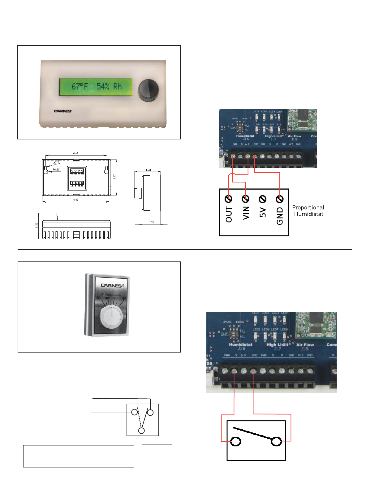
OPTIONAL ACCESSORY CONTROLS
WALL HUMIDISTAT, PROPORTIONAL CONTROL
Model HXHAM
The Model HXHAM is a wall-mounted, microprocessor-controlled
humidistat solution for humidity control. The HXHAM employs
a backlit LCD module, which displays both the ambient
temperature and humidity of the surrounding air. The
embedded software allows user navigation between temperature/
humidity viewing mode, setpoint adjustment mode, and outdoor
temperature/humidity viewing mode.
WALL HUMIDISTAT, ON-OFF CONTROL
Model HXHAA
Mount this humidistat four or five feet above the floor in freely
circulating air for average temperature and humidity to be
controlled for the entire space. Avoid locations near the hot or cold
air ducts and discharge air from the humidifier. Scale range is from
10-90% RH. Differential is 5% non-adjustable.
“N.C.” (Red) is switched to
common (Orange) during
RH Rise.
“N.O.” (Brown) is switched
to common (Orange) during
RH Drop.
BROWN (N. O.)
RED (N. C.)
(To Terminal 2 or 4)
Unit may be installed on either a flush switch box, a surface switch
box, or directly on a wall.
Mount with Number 6 screws provided for switch box mounting.
Different screws are required for wall mounting (not included).
NOTE: The HXHAA has 6” (152mm) leads and a green
grounding wire for use with non-conducting
conduit.
ORANGE (COMMON)
(To Terminal 2 or 4)
16
Page 17
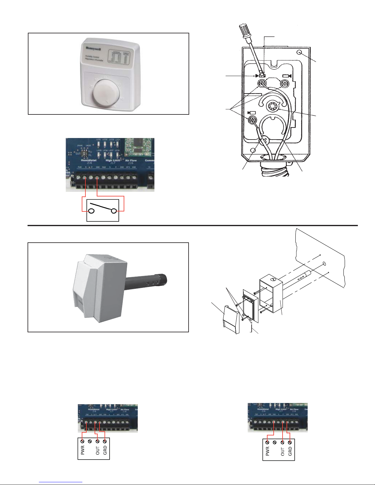
DUCT HUMIDISTAT, ON-OFF CONTROL
Model HXHAB
This duct mounted humidistat is installed in the return air duct to
sense the humidity level in the area being served. Scale range is
10-60% RH. Differential is 4-6% non-adjustable.
PUSH IN
RELEASE - 3
PUSH IN
TERMINAL - 3
PUSH TO
RELEASE
PUSH SCREWDRIVER
IN AND HOLD
MOUNTING
HOLES - 2
COM.
SETPOINT
ADJUSTMENT
DUCT HUMIDISTAT, PROPORTIONAL CONTROL
Model HXHAN
The Model HXHAN is an intelligent humidistat solution used
exclusively for duct mounted installations. The humidistat
is capable of providing both humidity and temperature
measurements from inside the duct. The microprocessor control
takes the temperature into consideration when calculating the
humidity to provide an extra degree of precision.
WIRE TO
HUMIDIFIER
TERMINAL 2 OR 4
WIRE TO
HUMIDIFIER TERMINAL
2 OR 4
The control should be located in the duct where it will be
affected by normal air flow. The control can be mounted in any
position but should be located on the side of the duct when
possible to make the setpoint adjustment easily accessible.
DUCT
Allen screws
Snap-on
plastic
cover
Aluminum housing
Use Allen wrench
to unlock cover
Remove any excess insulation from the duct that would prevent
the probe from extending a minimum of 4” (106mm) into the air
stream.
Make a 1-1/2” (38mm) hole in the duct for inserting the probe.
Use a gasket, sealer, or other means to seal the area between the
unit and the duct to ensure proper operation.
WHEN USED TO CONTROL ROOM RELATIVE HUMIDITY
WHEN USED AS HIGH LIMIT HUMIDISTAT
17
Page 18
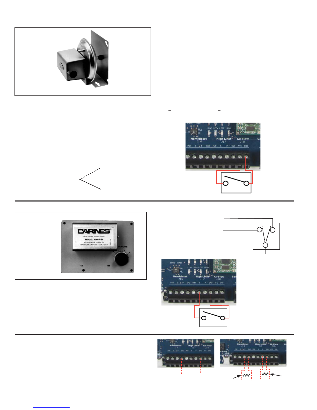
AIR FLOW SWITCH, PRESSURE DIFFERENTIAL TYPE
Model HXAAE
Air flow in the duct may be sensed by using this differential
pressure switch. The differential in pressure between the interior of the duct closes a switch when air is moving. Air pressure
differential as low as .07 w.g. may be sensed with this switch.
Environment:
Ambient Temperature Limits,
Shipping -40 to 140°F (-40 to 60°C).
Operating 35 to 140°F (0 to 60°C).
Humidity, 5 to 95% RH, non-condensing.
Locations, NEMA Type 1 indoor only.
Mounting: In vertical position on any surface free of vibration
(N.C.)
•
When there is an increase of air pressure to above setpoint, the
switch is switched from normally closed (N.C.), common ground
contact to normally open (N.O.) contact. On a decrease of air
pressure to below setpoint, normally closed, common ground
contact of the switch is switched to normally closed contact. Avoid
locations where excessive moisture, corrosive fumes, or vibrations
are present.
Setpoint:
Factory Set, 0.07” (1.8mm) w.g.
Field Adjustable, 0.07 to1” (1.8 to 25.4mm) w.g.
Sensing Element: Neoprene diaphragm.
Adjustment
Note: Units are shipped at minimum setpoint.
To increase setpoint, turn adjustment screw clockwise. Adjustable
0.05 +0.02” to 1.0” (1.25mm +0.5mm to 25mm) w.g. To decrease
setpoint, turn adjustment screw counterclockwise.
To Terminal 5 or 6 COMMON
Switch to “N.O.” on increase of pressure
•
To Terminal 5 or 6
(N.O.)
•
HIGH LIMIT HUMIDISTAT
Model HXHAD
The Model HXHAD is available to reduce the potential of
condensation occurring in the supply duct. The control must
be mounted a minimum of 10 feet downstream of the steam
distributor pipe. Setpoint range is 15-95% RH. Differential is 5%
non-adjustable.
The HXHAD may be mounted in any position on the outside
surface of the supply air duct where it is exposed to freely
circulating air (horizontal mounting is preferred).
“N.C.” (Red) is switched to
common (Orange) during
RH Rise.
“N.O.” (Brown) is switched
to common (Orange)
during RH Drop.
BROWN (N.O.) To Terminal 8 or 10
RED (N.C.)
ORANGE (COMMON)
To Terminal 8 or 10
EXTERNAL DDC CONTROL SIGNALS
The humidifiers can also accept a 0-10 volt DC signal to
modulate the output of the humidifier. Polarity must be
observed. Input impedance is 20K ohms. If a 4-20 mA input
signal is provided to the humidifier a 470 ohm, 1/4 watt resistor
must be installed as shown.
0-10 VDC
PROPORTIONAL SIGNAL
(BY OTHERS)
18
+
+-
-
PROPORTIONAL
HIGH LIMIT HUMIDISTAT
(BY OTHERS)
0-10 VDC
470 OHM
RESISTOR
(BY OTHERS)
4-20ma
PROPORTIONAL SIGNAL
(BY OTHERS)
+
-
+
PROPORTIONAL
HIGH LIMIT HUMIDISTAT
(BY OTHERS)
-
4-20ma
470 OHM
RESISTOR
(BY OTHERS)
Page 19
CONDENSATION PROTECTION
A third device may be desirable to provide condensation
protection in the duct system. A high limit humidistat may be
installed ten feet downstream from the steam distributor pipe. This
humidistat is normally set to 90-95% RH and opens the circuit if
the humidity level in the duct exceeds the setpoint. Use of this
device is recommended particularly when the humidifier is used in
applications where cooling air is being humidified or where a VAV
system may throttle back to a point where air flow is insufficient to
absorb the steam being introduced.
Either an on-off or proportional control high limit humidistat may
be used with Carnes humidifiers. If a proportional humidistat is
used the output of the humidifier will automatically be decreased
to reduce the possibility of condensation. Two proportional
humidistats may be used to control Carnes humidifiers if
desired. One humidistat is in the area to be humidified or
return duct and another humidistat is used as a high limit in
the supply duct. The humidifier will automatically select the
lowest signal to control the humidifier output.
CONTROL HUMIDISTAT / TEMPERATURE COMPENSATED
The HXHAT or HXHAMT can be used if your application has a
requirement for an outdoor temperature compensation feature.
Both controls will provide monitoring of RH percentage and
outdoor temperature, along with automatically adjusting the
RH setpoint as outdoor temperatures change. The HXHAT is
a dry contact on-off humidistat, while the HXHAMT provides a
0-10V signal in either a proportional or on-off configuration.
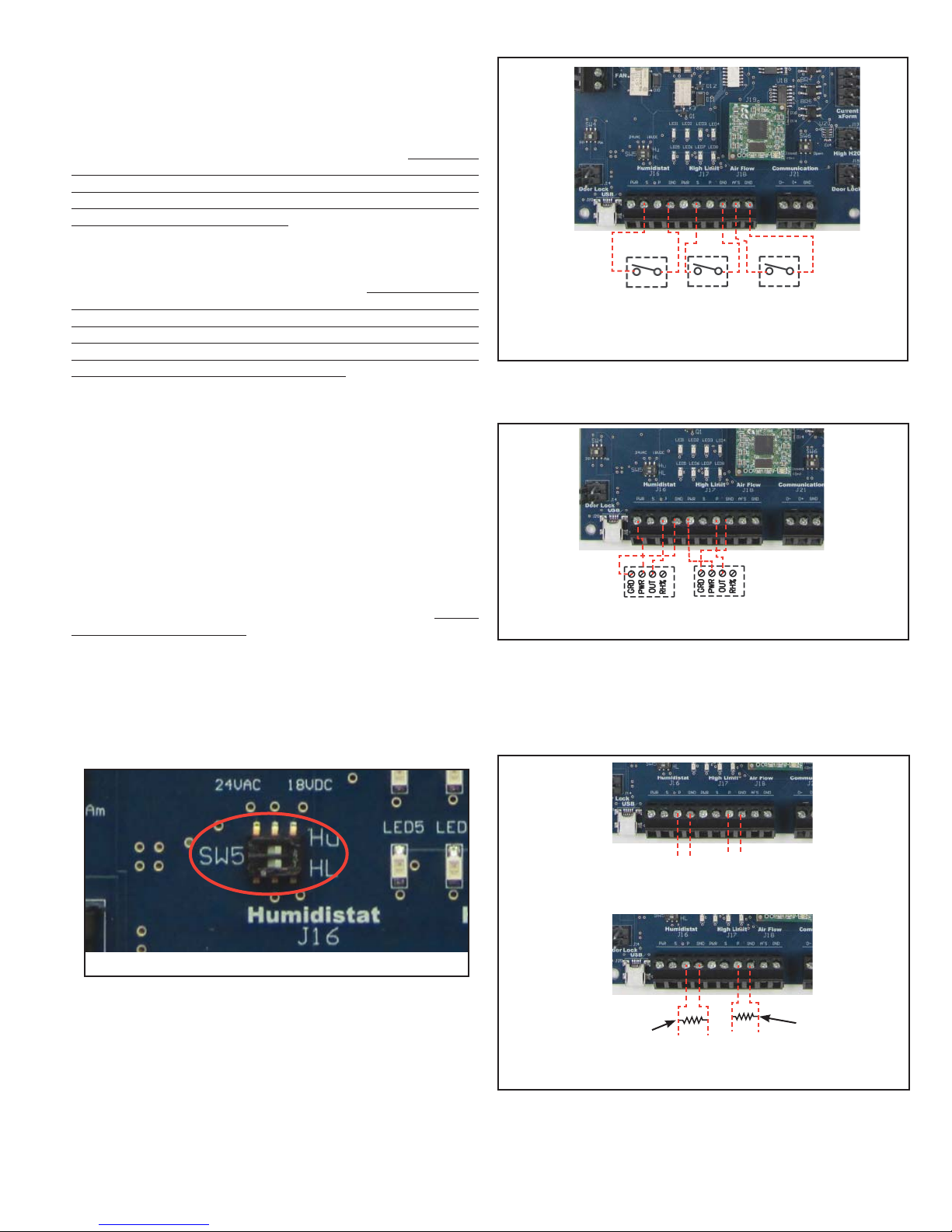
CONTROL CONNECTIONS
The circuit board can provide either a Carnes legacy 18VDC or an
industry standard 24VAC, as a supply for those humidistats which
require it. The supply for both the control humidistat and high limit
humidistat are output on pin1 of J16 and J17 respectively. 18VDC
is set as the supply default, but the switches on designators SW5
can be flipped to the left to alternatively supply 24VAC as seen in
Photo G for the H690-0107 circuit board (blue). The humidistat and
high limit can be changed independently. The switch labeled Hu is
switched for humidistat voltage output, and the switch labeled HL is
switched for high limit humidistat voltage output. Switch(es) in the
right position will supply 18VDC and switch(es) in the left position
will supply 24VAC.
Figure N
ON/OFF
HUMIDISTAT
ELECTRONIC CONTROL CIRCUIT BOARD
ON/OFF
HIGH LIMIT
HUMIDISTAT
Connections shown in Figure N are for typical on-off controls.
For Carnes proportional controls see the diagram Figure O. All
controls are shipped with detailed wiring instructions.
AIR FLOW
SWITCH
Figure O
PROPORTIONAL HUMIDISTAT
(BY CARNES)
PROPORTIONAL
HIGH LIMIT HUMIDISTAT
(BY CARNES)
EXTERNAL DDC CONTROL SIGNALS
Carnes humidifiers can also accept a 0-10 volt DC signal to
modulate the output of the humidifier. Polarity must be observed.
Input impedance is 20K ohms. If a 4-20 mA input signal is
provided to the humidifier a 470 ohm 1/4 watt resistor must be
installed as shown below (
Figure P)
.
Photo G
Two cylinder humidifiers may be wired for simultaneous or separate
and independent operation. Controls should be connected to the
terminals on the circuit board as shown below using No. 20 AWG
wire. Attempting to use two wires in a single control connection will
require a No. 22 AWG wire or less. See wiring diagram for parallel
connections. Avoid running control wiring near high voltage primary
wires due to the possibility of interference and signal distortion.
19
Figure P
+
0-10 VDC
PROPORTIONAL SIGNAL
(BY OTHERS)
470 OHM
RESISTOR
(BY OTHERS)
PROPORTIONAL SIGNAL
-
HIGH LIMIT HUMIDISTAT
+
4-20ma
(BY OTHERS)
+-
0-10 VDC
PROPORTIONAL
(BY OTHERS)
-
+
-
4-20ma
PROPORTIONAL
HIGH LIMIT HUMIDISTAT
(BY OTHERS)
470 OHM
RESISTOR
(BY OTHERS)
Page 20
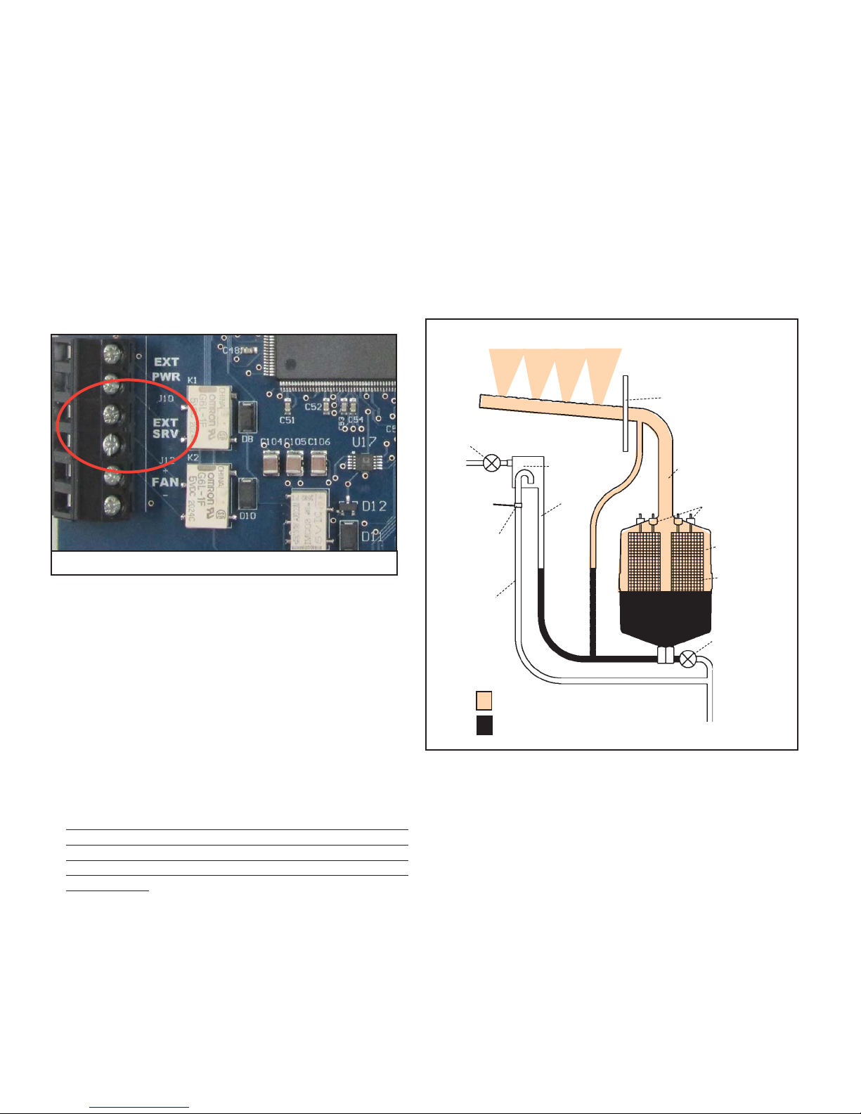
EXTERNAL MONITORING
Pins 1 and 2 of connector J10, shown in Photo H, are provided for
indicating operation of the humidifier at a remote location. When
the unit is operating, pins 1 and 2 (EXT PWR) are closed. Pins
3 and 4 of connector J10 (EXT SRV) are provided to indicate
the need for service. A “Service Required” warning on the home
screen of the LCD will indicate the type of service that is needed.
Both the EXT PWR and EXT SRV relays have a maximum ratings
of 0.3A at 125VAC or 1A at 24VDC maximum.
CarnesLink is an option to have full external monitoring and
control of your Carnes humidifier(s) by allowing the humidifier(s)
to link to a Building Management System (BMS) using one of the
following protocols: BACnet® (MS/TP), Modbus® (RTU),
Metasys® (N2) and Siemens® (FLN).The user friendly interface
on the True Touchscreen makes setting up CarnesLink easy
and convenient. (See the CarnesLink Communication Protocol
Installaion, Operation, and Maintenance Manual for further info.)
The circuit board also closes a power contactor allowing
current to flow to vertical electrodes sealed inside the
cylinder. Current flows between the electrodes using
minerals in the water as a conductor. The water is heated
to boiling and converted to steam which leaves the cylinder
through the flexible steam hose which is connected to the
steam distributor pipe.
The circuit board reacts to current flow between the
electrodes and automatically opens the fill solenoid valve
when more water is required to maintain the desired
output rate and closes when the desired rate is reached.
The operation of the drain solenoid valve is automatically
controlled by the circuit board which responds to any
changes in water conditions and drains the required
quantity of water to provide stable operation and long
cylinder life.
Figure Q
STEAM
DISTRIBUTOR
PIPE
FILL
SOLENOID VALVE
AIR GAP
STEAM
HOSE
Photo H
NETWORKING
If multiple units are required due to high capacity demand
(over 200 lb. per hour, single unit), networking can be done.
Units can be interconnected with parallel signal wiring. This setup
is usually done to facilitate running multiple units from a single
signal control (Humidistat, BMS System, etc.). For other
networking requirements, please contact factory.
CONTROL CONNECTIONS
FOR SAFETY: MAKE SURE TO TURN OFF POWER AT THE
EXTERNAL DISCONNECT BEFORE MAKING ANY INTERNAL
CHANGES TO THE HUMIDIFIER.
1. A 7/8” opening is provided on the top or bottom of the cabinet.
The control wiring should pass through the opening to the
provided connection points at J16, J17, and J18.
2. If an air flow switch or high limit humidistat is not used,
jumpers must be installed before the humidifier will operate.
On J17, jump terminals 2 and 4 together to bypass the high
limit. On J18, jump terminals 1 and 2 together to bypass the
air flow switch.
OPERATION
When the circuit board verifies all four basic controls have
been satisfied (control humidistat, high limit humidistat,
air flow, door interlock), a signal is sent to open a fill
solenoid valve, allowing water to flow across an air gap
into a standpipe. The standpipe provides a column of
water to be fed into the cylinder using gravity. The air gap
prevents the cylinder from pressurizing. See Figure Q.
The steam cylinder normally operates at a pressure of
approximately 1/2 psi.
NON CONTACT
HIGH WATER
SENSOR
OVERFLOW
TUBE
STAND
PIPE
FROM POWER
CONTACTOR
CYLINDER
VERTICAL
ELECTRODES
DRAIN
SOLENOID
VALVE
STEAM
WATER
TO DRAIN
As mineral deposits build up within the cylinder the water
level will slowly rise to uncovered electrode surfaces to
maintain the desired steam output rate. When mineral
deposits have covered all available electrode surfaces,
current flow will be reduced to a level where the desired
steam output cannot be reached and the service light will
signal the need for maintenance. When the cylinder is filled
with minerals it is easily changed in less than five minutes
(not including cool down time).
Important Note: Due to the many variables effecting the
operation of humidifiers (water condition, conductivity,
hardness, etc.) it could take up to 24 hours of operation
before a humidifier is truly operating normally and the water
is completely conditioned. Conditioned water is a state
where the amount of minerals dissolved within the water
is at a steady state. Conditioned water is more conductive
than new water from the fill valve.
20
Page 21
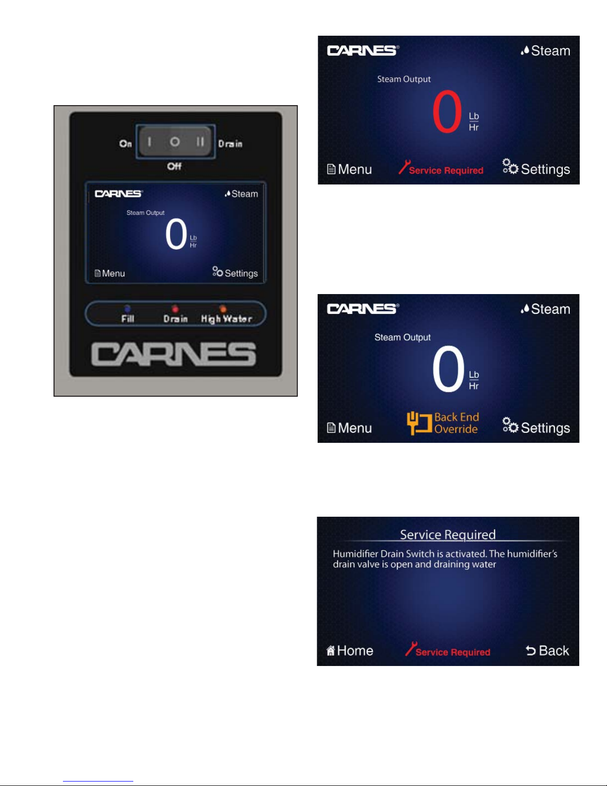
DISPLAYS AND INTERNAL CONTROLS
FRONT PANEL DISPLAYS & CONTROLS
The display on the front panel of the humidifier cabinet contains the “On-Off-Drain” switch, the LCD True Touchscreen
display and the “Fill”, “Drain”, and “High Water” LED.
“SERVICE REQUIRED” PAGE
The “Service Required” page outlines any service issues that
are in need of being resolved. Many issues can be traced back to
variability in water parameters, and often the solution can
be dealt with through the changing of cylinders or modifying
timer values within the “Settings” page. This page is used
to alert the user and direct them on the right path towards
resolution.
Figure P
“ON-OFF-DRAIN” SWITCH
In the “On” position the humidifier will operate if all
controls are calling for humidity. The “Off” position is used for
seasonal shut down if desired. The “Drain” position is used
to drain water from the steam cylinder for maintenance.
The fill solenoid valve will be on whenever the drain is
activated to reduce the drain water temperature.
LCD TRUE TOUCHSCREEN DISPLAY
This LCD True Touchscreen display offers a user
friendly interface to control and monitor many aspects
of the humidifier. The screen uses pressure sensitive
technology. Depressing on the labeled buttons on the
designated area of the screen will allow you to navigate
through the different menu pages.
“HOME SCREEN” PAGE
The “Home Screen” page is the main screen through which
most other pages can be accessed. The “Home Screen”
displays the current steam output in Lb./Hr. (or Kg/Hr.,
selected in “Settings”). The main “Home Screen” features
four navigation buttons, Carnes Logo (providing contact
info to the factory and the company website), Steam Menu,
Menu, and Settings. The “Home Screen” will display a
“Service Required” indicator when a current service issue
is indicated. The “Service Required” and Steam Output
number will illuminate red. Tap on “Service Required” to
access the service required page which indicates what
service issue is being detected.
When CarnesLink is being used, the “Back End Override”
indicator is displayed only when the connected building
management system requests the unit to be set to “off”
or “drain” while the unit is “on”. When selected more
information is provided about the override.
“FILL” LED
The FILL LED is a blue light illuminated when the Fill Valve is
activated. An activated Fill Valve allows water to flow into the
cylinder of the humidifier. An analogous indicator, and a
description of its operation, is offered in the “Menu” screen
under “Component Activity”.
21
Page 22
“DRAIN” LED
The DRAIN LED is a red light illuminated when the Drain
Valve is activated. An activated Drain Valve allows water
to drain from the humidifier. An analogous indicator, and a
description of its operation, is offered in the “Menu” screen
under “Component Activity”.
“HIGH WATER” LED
The HIGH WATER LED is an orange light illuminated
when the High Water Sensor is activated. An activated
High Water Sensor indicates that the water has risen to the
maximum allowable level in the cylinder. This can be a normal
situation, particularly if the cylinder is being filled with mostly unconditioned water. An activated High Water Sensor
can also be a sign that the cylinder is close to end-of-life
and needs replacing, or in rarer cases, the water in the
cylinder is not conductive enough for the fresh water
entering the humidifier. An analogous indicator, and
a description of its operation, is offered in the “Menu”
screen under “Component Activity”. More information on
troubleshooting High Water situations can also be found
under the “Help” button, on the “Menu” screen.
“ ” LOGO
The Carnes logo on the “Home Screen” will take you
to a page that displays the Carnes Company contact
information (address, phone number, and company
website). This feature is for the purpose of contacting the
factory for any startup questions, troubleshooting, or service
issues that may arise.
A Red “X” will be displayed to indicate if the control is not
sending a signal indicating a need for humidification. If any
one component is not satisfied, the “Home Screen” will
indicat on the display using “RED” illumination on the Steam
Output number and the “Steam” icon.
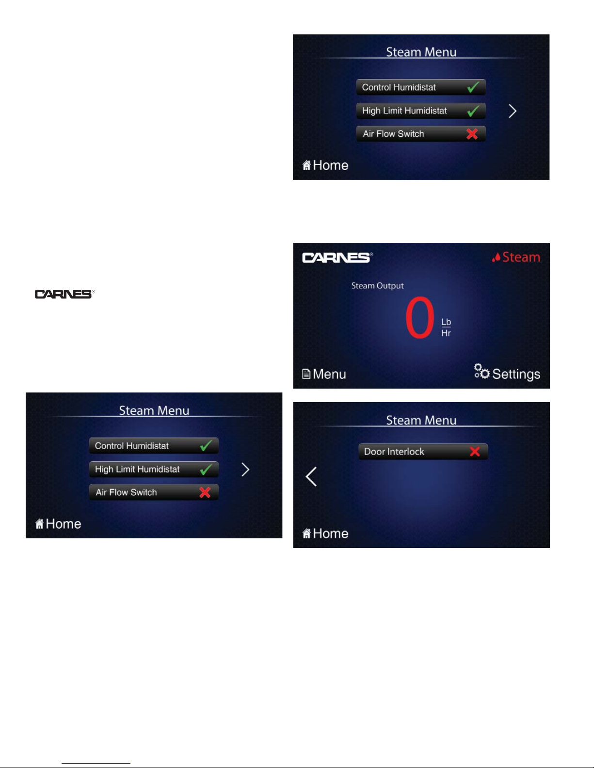
“STEAM” MENU
The “Steam Menu” page will display the status of the four
basic controls (Control Humidistat, High Limit Humidistat,
Air Flow Switch, and Door Interlock). The humidifier
will only produce steam when the unit is switched into
the “ON” position and if all four controls are satisfied.
A green “” will be displayed to indicate if the control is
sending a signal and requesting humidification.
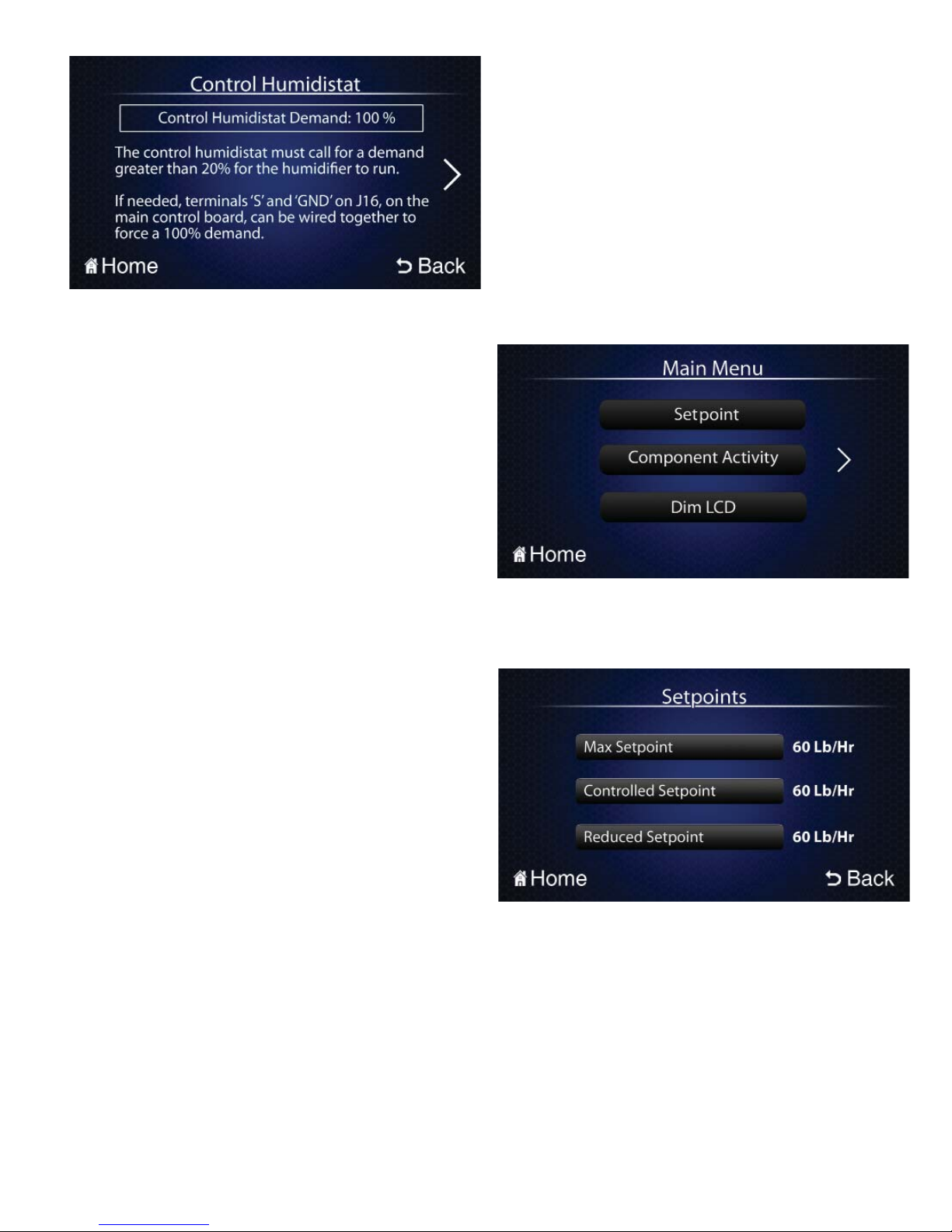
1. Control Humidistat - Explains the status and also
shows the current demand of the Control Humidistat.
The Control Humidistat must call for a demand greater
than 20% for the humidifier to run. If needed, terminals
‘S’ and ‘GND’ on J16, on the main control board, can be
wired together to force a 100% demand.
22
Page 23
2. High Limit Humidistat - Explains the status and shows
the current demand of the High Limit Humidistat. The
High Limit must call for a demand greater than 20% for
the humidifier to run. If needed, terminals ‘S’ and ‘GND’
on J17, on the main control board, can be wired together
to force a 100% demand.
The Control Humidistat, which provides the Control
Demand, is normally the humidistat located in the
room being humidified. It is either installed in the room
itself or the return air duct. The High Limit Humidistat,
which provides the High Limit Demand, is a safe-guard
humidistat, is usually set to a high level (80-90%), and
will shut down the humidifier if the humidity gets too
high in the supply duct. Without a High Limit Humidistat
properly installed the supply duct could reach a humidity
level where any steam entering the duct would readily
condense. Both Control Humidistats and High Limit
Humidistats are wired in the same way, only Control
Humidistats are wired to port J16 of the circuit board and
High Limit Humidistats are wired to port J17. Both ports
have the same number of pins and connection layout.
3. Air Flow - Explains the status of the Air Flow switch.
The Air Flow switch must sense proper air flow in order
for the humidifier to activate. Insufficient air flow or
an improperly installed air flow switch will cause the
indicator to change to a red “X” and the unit will not
operate. If needed, terminals ‘AFS’ and ‘GND’ on J18,
on the main control board, can be wired together to force
activation of the switch.
4. Door Interlock - Explains the status of the Door Interlock
switch. The Door Interlock needs to be engaged for the
unit to operate. This can be accomplished by either
locking the door shut or pulling out the plunger for
temporary operation while servicing the unit.
MENU
The “Menu” page displays four features: Setpoint,
Component Activity, Dim LCD and Help. Tapping any of
these buttons will show dialog explaining the subject or
status of that button and display pictures.
When using an on-off humidistat, the percentage
should be either 100% or below 20%. In this case, the
control is either calling for full output or no output. On-Off
humidistats are dry contact switches. They will have two
wires; each connected to pins 2 and 4 (in no particular
order/polarity).
For a proportional humidistat, any percentage value
is possible between 0% and 100%. In this case, the
humidifier can be modified to output any fraction of its
max output. If the proportional control falls to 20% or
below, the humidifier is shut off. The input signal of a
proportional humidistat must be 0-10V DC. Proportional
humidistats will have three wires, with ‘power’ going to
pin 1, ‘signal’ to pin 3 and ‘ground’ to pin 4. In lieu of a
humidistat, a DDC signal from a building management
system may also be used. Here, the ‘signal’ should be
connected to pin 3, and ‘ground’ to pin 4. In this case,
‘power’ can be ignored. A DDC signal must be of a
0-10V signal by adding a 470 ohm resistor between the
‘signal’ (pin 3) and ‘ground’ (pin 4).
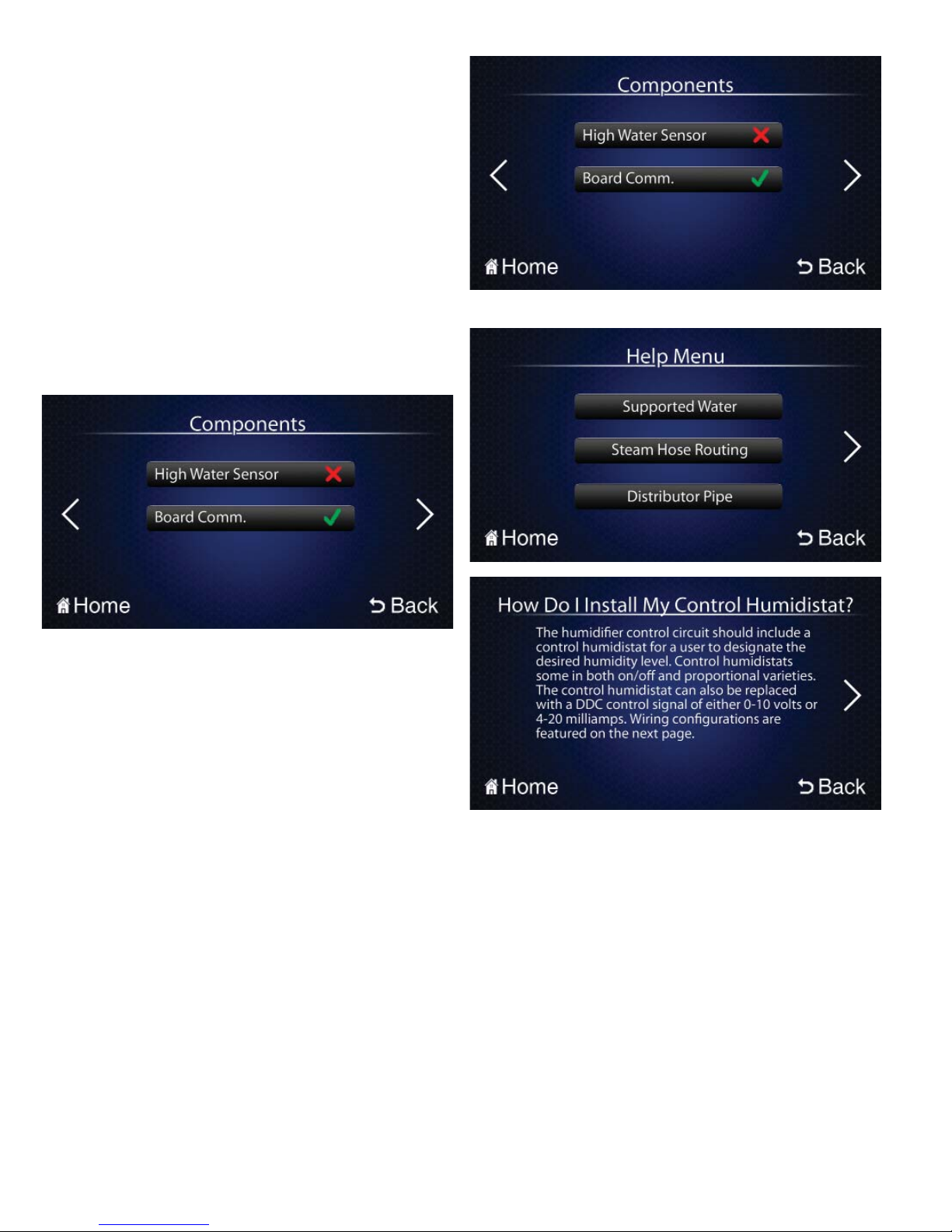
“SETPOINTS”
The Setpoints page displays the Setpoints (the target
steam output of the humidifier) associated with the
unit. There are three different Setpoints, but only one
Setpoint is active at any given time. Each Setpoint is
accompanied by the current value of the Setpoint to the
right, and an indicator that represents its status.
The Max Setpoint is the user-specified Setpoint that is
active when no external controls or internal reduction is
taking place. The Max Setpoint is always modifiable via
the “Max Output Adjust” within the “Settings” menu.
23
Page 24
The Controlled Setpoint is the Setpoint when a
humidifier (Control or High Limit), reduces the
target output of the humidifier due to changing room
requirements.
The Reduced Setpoint is active when the unit requires
a reduction in output due to a high water situation.
The Setpoints have the following priorities: The Reduced
Setpoint has the highest priority and always overrides
the Controlled Setpoint and the Max Setpoint when
active. The Controlled Setpoint has the next highest
priority, and always overrides the Max Setpoint. It
should be noted that the Reduced Setpoint is always
lower than or equal to the Max Setpoint (or Controlled
Setpoint, if active) and the Controlled Setpoint is always
lower or equal to the Max Setpoint.
“COMPONENT ACTIVITY”
“HELP” MENU
The Component Activity page lists all internal components
that can switch on and off during operation. This includes
the Fill Valve, Drain Valve, Contactor, High Water Sensor,
and Board Communication. Each component listed is
accompanied by a green “” or a red “X” indicator representing whether or not the component is currently ‘on’. The
Fill Value is on when the unit is either filling or draining
the cylinder. The Drain Valve is on when the humidifier is
draining and can be on while the humidifier is producing
steam. The High Water Sensor is on when the humidifier
has identified a high water situation. When in a high water
situation, the fill valve is disabled for 5 minutes. At the end
of 5 minutes the high water sensor light will go out, the fill
valve will open, if there is a call for more humidity, and then
the unit will continue normal operation. High water sensors
can be cumulative depending on the condition of the water.
The other component in the “Component Activity” page
is the Board Communication (Comm.) button. The
Board Communication button represents whether the
touchscreen controller on the circuit board is properly
communicating with the microcontroller and that the
microcontroller is properly communicating with the data
communication chip, if present. The Communication
indicator is a green “” when the LCD display is
communicating properly with the control board. If there is a
red “X”, the touchscreen has likely lost communication with
the control board, and the information on the screen may be
inaccurate. For troubleshooting, contact Carnes Company
at 608-845-6411.
24
Page 25
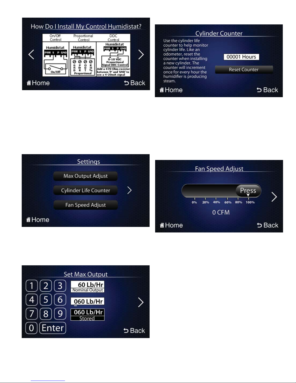
The help pages consist of buttons labeled with subjects.
When a button is pressed, information will be given about the
subject in question. A basic help page consists of text and/or
diagrams to help the user through basic problems. For
example, in the pictures above, the question “How Do I Install
My Control Humidistat?” is answered with a diagram and
corresponding text. Some pages consist of more buttons
to help guide a user through different processes. These
buttons can be used and referenced as needed.
“SETTINGS” MENU
Cylinder Life Counter
This page consists of a counter where the user can monitor
the life, in hours, of the cylinder. When changing a cylinder,
press the ‘Reset’ button on this page to reset the timer.
The Cylinder Life Counter only counts the amount of actual
runtime of the cylinder (the time when the contactor is
pulled in). The counter value is saved even when the
humidifier is powered down. The national average cylinder life
is about 1150 hours, but this can vary greatly depending on
individual water conditions.
Fan Speed Adjust
The “Settings” menu has pages where all operational
values can be set. It is password protected by default, with
a default password of ‘1212’. The default password can be
changed or disabled under the “Change Password” page.
See “Settings Password” page for more details.
Max Output Adjust
The maximum steam output of the unit can be set on
this page. The maximum output value cannot exceed the
nominal output value of the unit and cannot be set below
20% of the nominal output. The nominal output of the unit is
listed on the nameplate and the “Electrical Data” help page.
This page consists of a slider bar that can change the speed
of the fans when the humidifier is connected to an optional
blower box. This slider bar will not affect the operation of the
humidifier if no blower box is attached. The bar can change
the speeds of the fans from 0 to 100% of the max fan speed.
Also displayed on this page is an estimate of the current fan
air output, in Cubic Feet per Minute (CFM). This adjustment
is particularly useful if the humidifier is of a smaller capacity,
and less noise from the fans is appreciated.
25
Page 26
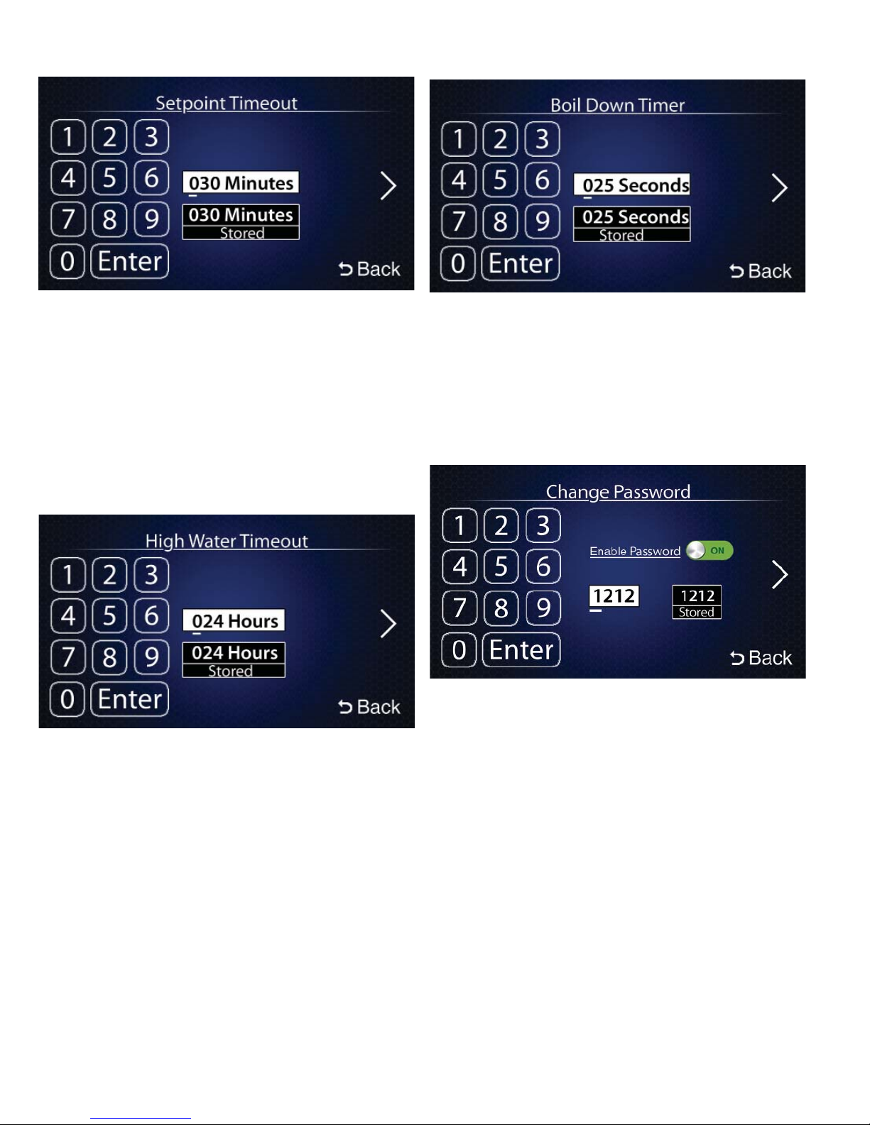
Setpoint Timeout
Boil Down Timer
This page is where the Setpoint Timeout value is set. The
maximum amount of time allowed for the unit to reach
Setpoint during a fill sequence is designated by the Setpoint
Timeout. Its default value is 30 minutes, but can be set as
high as 255 minutes. After the timer expires during a fill
sequence, the humidifier assumes the drain valve is stuck
open (due to sediment buildup), and begins pulsing the drain
valve to attempt to unclog it. After the pulsing routine, the
humidifier will attempt to reach Setpoint for a second and
third time. After the third attempt without reaching Setpoint,
the unit will shut down.
High Water Timeout
This page is where the High Water Timeout value is set.
This is the maximum amount of time allowed for the unit to
run in a “Reduced Setpoint” mode (see Setpoints page). The
timeout has a range from 0 to 168 hours, with the default
being 24 hours. If the humidifier Setpoint is artificially
reduced due to a high water situation, the humidifier will
continue to run. If the humidifier cannot reach normal max/
controlled Setpoint, the humidifier will shut down after the
High Water Timeout value elapses.
This page is where the Boil Down Timer is set. The Boil
Down Timer is variable between 0 and 255 seconds, with
a default value of 25 seconds. Setting the Boil Down Timer
higher will result in an increased water level, and less
conditioned water. This may be helpful in reducing low water
level induced arcing and corrosion of cylinders. More water
is consumed by the humidifier when the Boil Down Timer
value is increased.
Settings Password
This page is where the password for the settings menu can
be changed or disabled. If the password for the Settings
menu is forgotten the it can be reset. To do this, remove
power to the humidifier, flip the switch SW3’s bottom “Clear”
switch to the right and power the unit back on. Return the
switch’s afterwards from the right to the left.
The different buttons on both setting pages allow for the
changing of different values. Below is a brief summary of
each, and more information can be accessed within the
page itself.
26
Page 27
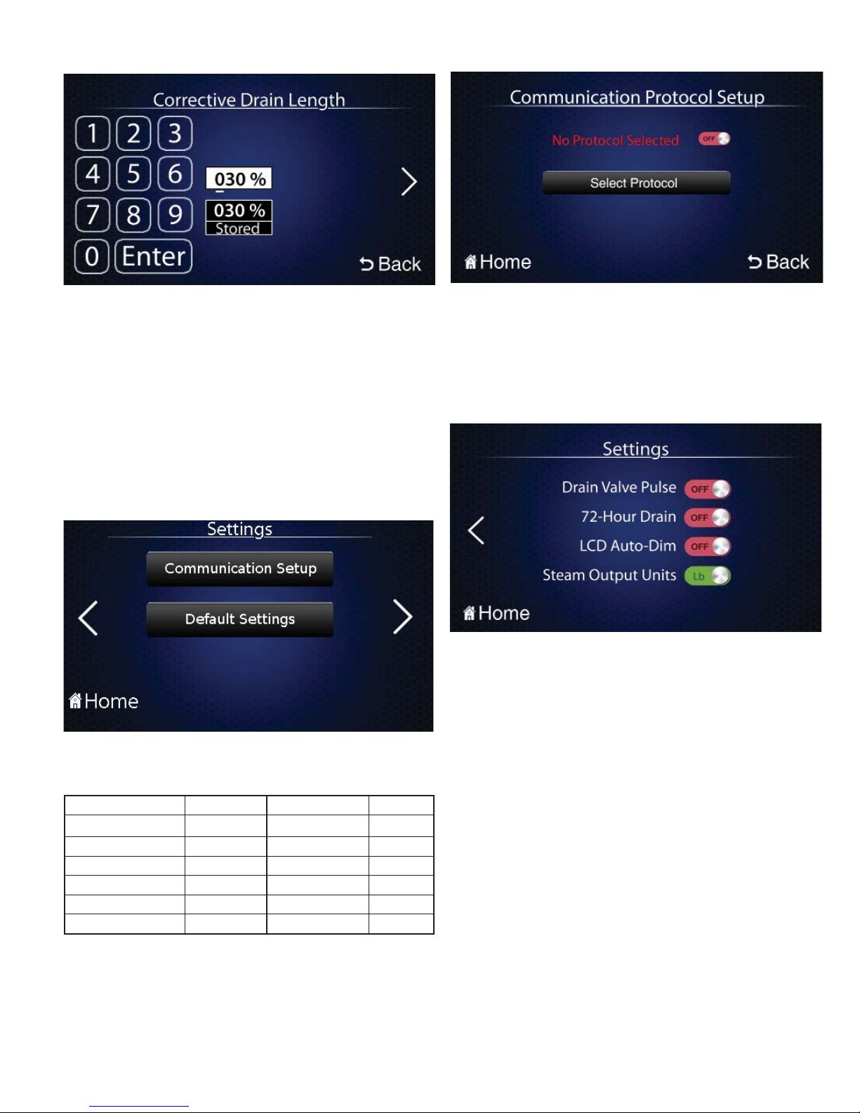
Corrective Drain Length
CarnesLink Communication Protocol Setup
This page is where the Corrective Drain Length is
set. This value represents how much water should be
drained from the cylinder when the humidifier senses a
corrective drain is needed. As water boils from the humidifier,
minerals increase in the cylinder causing the water to get
more conductive. Increasing the length of the drain flushes
more conductive material from the humidifier, decreasing
the water conductivity. The input here is a percentage value.
To set the Corrective Drain Length to drain 20% of the
cylinder during a corrective drain, input 020. To drain all the
tank, input 100. 030 is the default value, and only multiples
of 10 between 20 and 100 can be entered.
Default Settings
This page is where you can select and setup the
communication protocol you will be using with your Building
Management System (BMS) for full external monitoring
capabilities. (See the CarnesLink Communication Protocol
Installation, Operation and Maintenance Manual for further
information.)
ON/OFF Setting Buttons
There are a few operational options that do not need
separate pages, and therefore are only enabled/disabled
via the ON/OFF Buttons on the main “Settings” menu page.
Their functionality is described as follows:
Selecting Default Settings on the settings page will allow
for the restoring of factory default settings. The factory
settings will be set to the following:
Setting Default Setting Default
Max Output Nominal Output Comm. Setup Unchanged
Fan Speed 100% Drain Pulse Off
Setpoint Timeout 30 Min. 72-Hour Drain On
High Water Timeout 24 Hrs LCD Auto-Dim Off
Boil Down Timer 25 Sec Steam Output Units Lb
Corrective Drain Length 30%
Restoring default settings can be helpful when troubleshooting an oddly behaving humidifier. Although some
settings will stay visible on their respective screens after
applying a factory reset, it is recommended to take note
of all adjustments previously applied as some may be
important for efficient operation given specific water
conditions.
The Drain Valve Pulse option is enabled by default.
This option allows the drain valve to pulse when the
humidifier executes a corrective drain. This actuates the water
within the drain piping, allowing for minerals buildup to be
discharged more easily. Enabling this option will make the
unit noisier whenever a corrective drain is executed.
The 72-Hour Drain is disabled by default. This option,
when enabled, allows the humidifier to drain the cylinder
completely after 72 hours of idle operation.
The LCD Auto-Dim is disabled by default. This option,
when enabled, will automatically turn off the backlight of the
LCD after 15 minutes of idleness. This feature can save on
energy consumed.
The Steam Output Units is disabled or set to “Lb.” by
default. This option, when set to “Kg.”, will turn the steam
readout on home page into Kg./Hr .instead of Lb./Hr.
27
Page 28

HUMIDIFIER MANDATORY PRE-STARTUP CHECKLIST
Unit Serial #: _____________________ No. of Humidifi ers: ______________________________________________
Model #: _________________________________ Voltage: _______ V/ ___ Ph. Steam Output: _______ lb./hr.
Customer/Job: ___________________________ Address: ______________________________________________
WATER QUALITY:
Well Water ______ City Water ______ Softened Water ______
Water Conductivity (if known): mhmos: ______ Hardness: ______ gr.
HUMIDIFIER MOUNTING:
Clearances around the unit Acceptable
Front (door opens freely?) yes no
Top (steam lines) yes no
Bottom (fill, drain, controls) yes no
Both Sides yes no
STEAM HOSE: CONDENSATE HOSE:
Sloping up 2 in. every 12 in. yes no
Sloping down 0.5 in. every 12 in. yes no
Lengths/Size ______/______
Material ______________________________
Runs of hose over 12 ft. yes no
(if yes, drain T is needed, check IOM for details) (if yes, drain T is needed, check IOM for details)
Can condensate be trapped Can condensate be trapped anywhere
anywhere in the steam line? yes no
Lengths/Size
18" (Residential/Commercial)
38” (Dual Cylinder Cabinet)
12” (Residential/Commercial)
16” (Residential/Commercial)
Sloping back to drain yes no
Condensate routes to drain?
______/______
Material __________________________
Runs of hose over 12 ft. yes no
in the condensate line? yes no
WATER SUPPLY LINE (do not use hot water):
3/8 in. connection at fill yes no
Water supply shutoff within 6 ft. yes no
DRAIN LINE:
Connection pipe fitting to trap yes no
CYLINDER:
Properly installed and secured yes no
Wire connectors pushed completely down on electrode rods? yes
WIRING:
No lose wiring connections and connectors yes no
CONTROLS:
Humidistat location:
High limit location:
Air flow location: __________________________________
________________________________________________
POWER:
Voltage/current rating and fuse correspond to spec label yes no
Disconnect switch located close to humidifier unit yes no
_________________________________
__________________________________
Water pressure 20-120 psi yes no
PVC yes no
Slope to drain yes no
Water pressure 20-120 psi yes no
no
Copper yes
Humidistat to terminal J16 yes no
High limit to terminal J17 yes no
Air flow to terminal J18 yes no
no
Started by: ________________________________________ Date of Startup: ___________________
Company: ________________________________________
28
Page 29
HUMIDIFIER STARTUP CHECKLIST
Unit Serial #: _____________________ No. of Humidifi ers: ______________________________________________
Model #: _________________________________ Voltage: _______ V/ ___ Ph. Steam Output: _______ lb./hr.
Customer/Job: ___________________________ Address: ______________________________________________
PRELIMINARY:
• Pre-startup Checklist completed yes no
If no, perform Pre-startup Checklist before starting humidifier.
STARTUP PROCEEDURE:
The prerequisites for the humidifier filling and contactor pulling in to make steam are as follows:
• Front door closed or door interlock switch pulled out yes no
• Water supply valve opened yes no
• Main disconnect switched on yes no
• Turn on the On-Off-Drain switch yes no
CONTROLS:
• Installed controls match configuration yes no
• Control setpoint yes no
• Proportional wall humidistat (HXHAM, HXHCH or HXHCG) yes no
• On/Off wall humidistat (HXHAA) yes no
• Air flow switch (HXAAE) yes no
• Pressure differential high velocity air flow switch (HXAAF) yes no
• Duct mounted, proportional high limit switch (HXHAN) yes no
• Wall mounted high limit humidistat (HXHAD) yes no
The humidifier will undergo a self-diagnostic when the power is turned on activating the LED’s and other internal components.
If the above listed prerequisites are fulfilled, the humidifier will start filling the cylinder and begin normal operation.
NOTE: Most water does not contain enough conductivity for full boil on initial startup and after new cylinder replacement.
Units will need to concentrate the water over a time period (up to 24 hours). It’s normal for the humidifi er status to cycle
between “Filling” and “High Water” (max water level) during this time period.
Started by: ________________________________________ Date of Startup: ___________________
Company: ________________________________________
29
Page 30

HUMIDIFIER STARTUP & OPERATION
Unit Serial #: _____________________ No. of Humidifi ers: ______________________________________________
Model #: _________________________________ Voltage: _______ V/ ___ Ph. Steam Output: _______ lb./hr.
Customer/Job: ___________________________ Address: ______________________________________________
PRELIMINARY:
• Pre-startup Checklist completed yes no
If no, perform Pre-startup Checklist before going to the starting procedure.
• Startup Checklist completed yes no
If no, return to the Startup Checklist before going to the startup procedure.
INITIAL STARTUP:
While the external disconnect is in the off position, be sure
that the terminal connectors on the top of the cylinder are
firmly secured and pushed completely down over the pins in
the cylinder.
1. Open all the water supply valves external to the humidifier.
2. Turn external disconnect switch on.
3. Turn on optional circuit breakers if present.
4. For safety, door interlock disconnects power to cylinder(s)
when the door is opened.
The humidifier may be operated for service purposes by pulling
out the knob of the door interlock switch into a fixed, always
on, position. CAUTION: HIGH VOLTAGES ARE PRESENT.
5. Turn the “On-Off-Drain” switch to the “On” position. The
blue fill LED will turn on.
6. The Steam Indicator will turn red if any of the basic four
controls on the home page are not ready, indicated with a
red
“X”
.
7. Adjust the controls as necessary to satisfy the
requirements for steam output (see Controls and Home
Page for more information). The humidifier will begin to
operate if all four controls are satisfied.
8. As water slowly fills into the cylinder, the LCD Lb./Hr.
output will begin to increase when water comes in contact
with the electrodes.
9. Water will continue to fill until output is 10% above
setpoint. If water reaches the top of the cylinder before
setpoint is reached, the “High Water Sensor” will be
activated and the fill will close.
10. When starting a new cylinder and fresh water, the fill and
drain solenoid valve may cycle for brief periods until the
water has come to a complete boil.
11. In areas with low conductivity water, full output may not be
reached until the humidifier has conditioned the water by
repeated cycles of filling, boiling, and refilling. The length
of this process will vary but may require several hours, up
to a day, under certain conditions.
AUTOMATIC DRAIN CYCLE:
The circuit board automatically controls the operation of the
drain valve to react to two situations:
Controlling mineral content:
1. When the current reaches 10% above the active setpoint,
the fill solenoid valve closes and water gradually boils away
in the cylinder. Because the quantity of water covering the
electrode surface is being reduced, current slowly falls.
2. An internal timer within the operation algorithm starts
to count seconds when steam output drops to 90% of
setpoint.
3. The timer runs until steam output drops to 90% of setpoint.
4. If steam output drops too rapidly during this transition,
a corrective drain is necessary to reduce the mineral
concentration of the water.
5. If the steam output changes slowly it indicates that mineral
concentration is satisfactory and a corrective drain is not
necessary.
6. Measurements are made during each cycle and a drain
only occurs when necessary thereby maximizing energy
and water usuage efficiency.
Reduced Overcurrent
1. If current to any electrodes in the cylinder reaches more
than 20% above the setpoint, the drain valve will open.
2. Draining water from the cylinder reduces current by
covering less electrode surface.
3. If current is successfully reduced to acceptable levels
normal operation continues.
4. If current is not reduced because of mineral blockage in the
drain lines or solenoid valve, the power contactor will be
opened for approximately 10 seconds while the drain valve
remains open.
5. If current is successfully reduced, normal operation
continues.
6. If current is not reduced the cycle is repeated 8 more
times. If still unsuccessful, the humidifier is placed in an
overcurrent shutdown mode and the “Service Required”
page will be updated accordingly.
30
Page 31
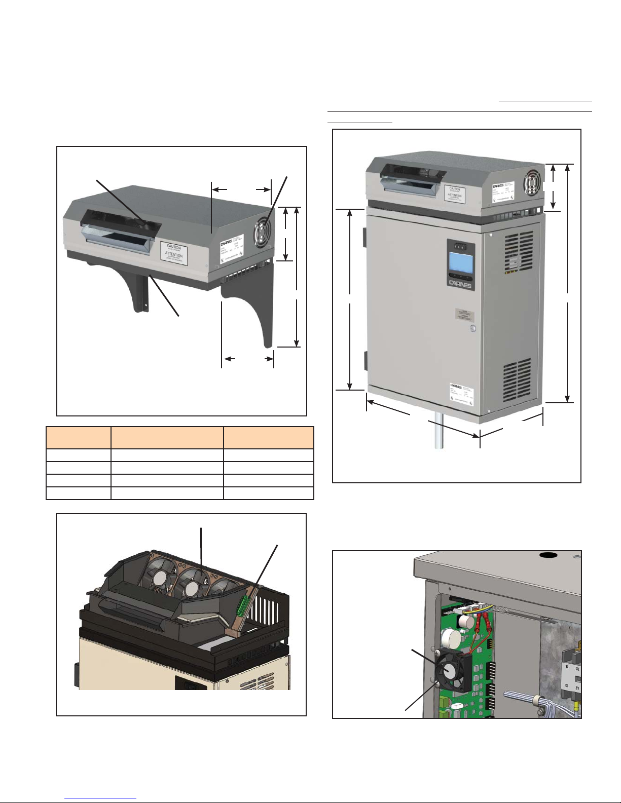
FAN DISTRIBUTION UNITS
Fan distribution units are available for use in areas which do not
have duct systems or where duct air temperatures are too low
to provide sufficient humidification. For example, in computer
areas, the desired relative humidity may not be possible in the
conditioned space without causing condensation in the duct.
Fan distribution units may be either remote mounted or directly
mounted on the humidifier unit.
Fans
Fans
12-1/2”
Box
6-3/8”
Fan distribution units must be mounted securely on a level and
plumb surface at least three feet below the ceiling for a Model
HXBHB and at least four feet below the ceiling for a Model
HXBHC to prevent steam condensing on the ceiling surface. Allow
20 feet in front of the HXBHB and 30 feet in front of the HXBHC
for the steam to be absorbed into the air. Do not mount the units
above any items that would be damaged if a water leak or spitting
were to develop.
6-3/8”
Steam
Hose
12-1/2”
Photo I
Humidifier
Model
H_AH 005, 010 HXBHB (1 Required)
H_DH 020, 030 HXBHB (1 Required)
H_GH 030, 040, 050, 060, 080, 100 HXBHC (1 Required)
H_HH 125, 150, 175, 200 HXBHC (2 Required)
Nominal Steam
Output Rate
Fans
Remote Mounted
Fan Unit Model
12-Pin Fan
Connection
9-5/8”
25”
20”
11-3/4”
31-3/8”
Photo L
A Mounted Fan Distribution Unit and its associated humidifier
are shipped as a complete assembled unit. In this case, a 12-wire
connection is made from the circuit board to the 12-Pin fan
connection (Green). This connection is already assembled in the
factory.
Photo J
Cooling fan for
circuit board
when mounted
and remote fan
distribution unit
is used.
999-5739
Cooling Fan included with all fan distribution units as well as with
all other units manufactured. As soon as power is supplied, the fan
will start to run from the 12 volt source from circuit board.
31
Page 32
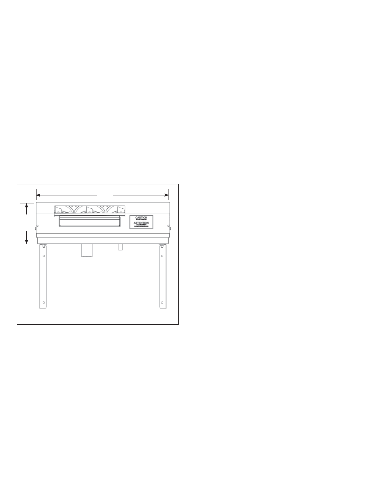
A Remote Fan Distribution Unit comes with two separate
male plugs to connect 12-conductor wire from the humidifier to
the fan distribution unit at a remote location. One of the male
connectors goes to the humidifier’s female connector, the other
goes to the remote unit. We recommend Alpha Wire 1181C
(non-Carnes) as an appropriate 12 conductor wire, but there are
many available that will suffice. Each conductor should be rated
at minimum for 1 Amp. If individual wires are used, utilize 26 or
28 gauge wire.
When connecting the humidifier male ends to the wire, pin 1
of the humidifier connector should be routed to pin 1 of the fan
distribution unit connector. Pin 2 should be routed to pin 2,
etc. Use a small regular head screwdriver to connect each
conductor into the male connector. It is important to make sure the
conductor is grasped inside the screw compression, and not the
wire insulation.
A remote fan distribution unit should not be mounted any more
than 40 feet away from the humidifier but this is dependent on the
capacity of the unit. Small capacity units cannot provide steam
at greater distance. See Table 3-A, page 7. When wiring the fan
distribution unit remotely, it is not absolutely necessary to wire
through the electrical conduit, but it is recommended for providing
some strain relief on the connector.
20”
6-3/8”
Photo K
32
Page 33
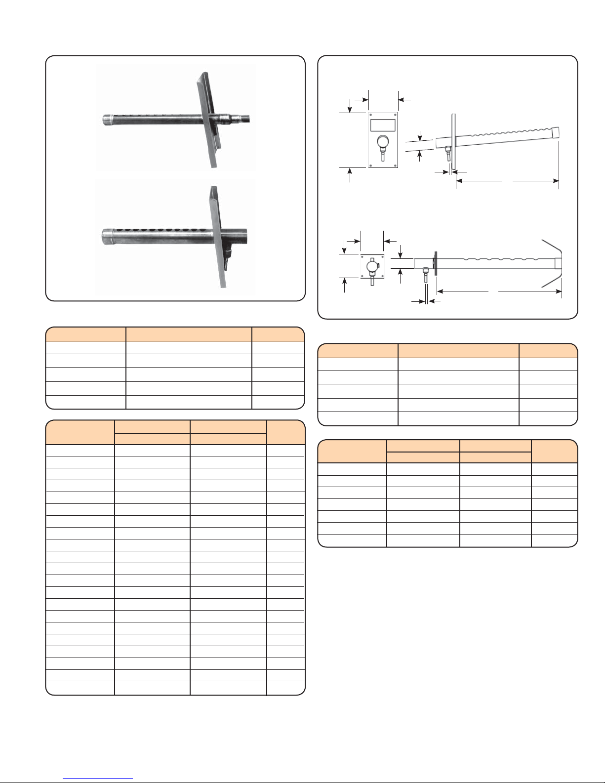
STEAM DISTRIBUTOR PIPES
Lengths 012-036
5”
(127)
9-1/2”
(241)
Lengths 048-120
4”
(102)
T
3/8”
N
Distributor Pipes for Models: HTA, HSA, HTD, HSD
PIPE N T
HXPBB012S 11-13/16 (300mm) 7/8
HXPBB018S 17-13/16 (452mm) 7/8
HXPBB024S 23-13/16 (605mm) 7/8
HXPBB030S 29-13/16 (757mm) 7/8
HXPBB036S 35-13/16 (910mm) 7/8
Minimum**
Maximum**
PIPE N N T
HXPBB040S 35 (889mm) 38 (965mm) 7/8
HXPBB044S 39 (991mm) 42 (1067mm) 7/8
HXPBB048S 43 (1092mm) 46 (1168mm) 7/8
HXPBB052S 47 (1194mm) 50 (1270mm) 7/8
HXPBB056S 51 (1295mm) 54 (1372mm) 7/8
HXPBB060S 55 (1397mm) 58 (1473mm) 7/8
HXPBB064S 59 (1499mm) 62 (1575mm) 7/8
HXPBB068S 63 (1600mm) 66 (1676mm) 7/8
HXPBB072S 67 (1702mm) 70 (1778mm) 7/8
HXPBB076S 71 (1803mm) 74 (1880mm) 7/8
HXPBB080S 75 (1905mm) 78 (1981mm) 7/8
HXPBB084S 79 (2007mm) 82 (2083mm) 7/8
HXPBB088S 83 (2108mm) 86 (2184mm) 7/8
HXPBB092S 87 (2210mm) 90 (2286mm) 7/8
HXPBB096S 91 (2311mm) 94 (2388mm) 7/8
HXPBB100S 95 (2413mm) 98 (2489mm) 7/8
HXPBB104S 99 (2515mm) 102 (2591mm) 7/8
HXPBB108S 103 (2616mm) 106 (2692mm) 7/8
HXPBB112S 107 (2718mm) 110 (2794mm) 7/8
HXPBB116S 111 (2819mm) 114 (2896mm) 7/8
HXPBB120S 115 (2921mm) 118 (2997mm) 7/8
**See Note A
4”
(102)
T
N
3/8”
Distributor Pipes for Models: HTG, HSG, HTH, HSH
PIPE N T
HXPBC012S 11-13/16 (300mm) 1-5/8
HXPBC018S 17-13/16 (452mm) 1-5/8
HXPBC024S 23-13/16 (605mm) 1-5/8
HXPBC030S 29-13/16 (757mm) 1-5/8
HXPBC036S 35-13/16 (910mm) 1-5/8
PIPE N N T
HXPBC048S 43 (1092mm) 46 (1168mm) 1-5/8
HXPBC060S 55 (1397mm) 58 (1473mm) 1-5/8
HXPBC072S 67 (1702mm) 70 (1778mm) 1-5/8
HXPBC084S 79 (2007mm) 82 (2083mm) 1-5/8
HXPBC096S 91 (2311mm) 94 (2388mm) 1-5/8
HXPBC108S 103 (2616mm) 106 (2692mm) 1-5/8
HXPBC120S 115 (2921mm) 118 (2997mm) 1-5/8
**NOTE A
The mounting plate on these pipes is adjustable to compensate
for slight variations in ductwork dimensions. The “N” dimension is
shown at both maximum and minimum depending on the position
of mounting plate. A mounting strap is provided on the end of the
pipe to secure to the top or side of the duct for support.
MATERIAL
Standard distributor pipes are fabricated from stainless steel.
Minimum** Maximum**
33
Page 34
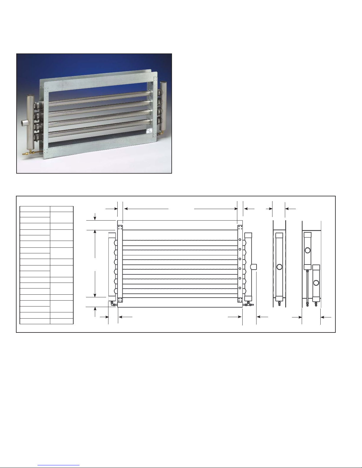
CARNES STEAM MANIFOLDS reduce the non-wetting distance when
required because of space constraints in duct system.
SHORT ABSORPTION
MANIFOLD
Carnes Steam Manifolds are designed to
provide dry steam with rapid absorption in the
duct air stream. It achieves this by distributing
steam evenly across the face of the duct. The
distance needed for absorption is dependent
on a number of factors, some of which are air
velocity, steam volume, air temperature, and
characteristics of air flow in the duct. For
minimum absorption distance, the manifold should
be located in the warmest air stream of the duct
and where fully developed laminar air flow occurs.
Table 5
Duct Height Tubes
012
014
016 4
018
020
022 6
024
026
028 8
030
032
034 10
036
038
040 12
042
044
046 14
048 15
3
5
7
9
11
13
1-1/2”
3” (76)
Duct
Height
3” (76)
(38)
3-1/2” (89)
Duct Width
5”
(127)
1-1/2”
(38)
4”
(102)
Type
B, C
Type
D
6”
(152)
34
Page 35
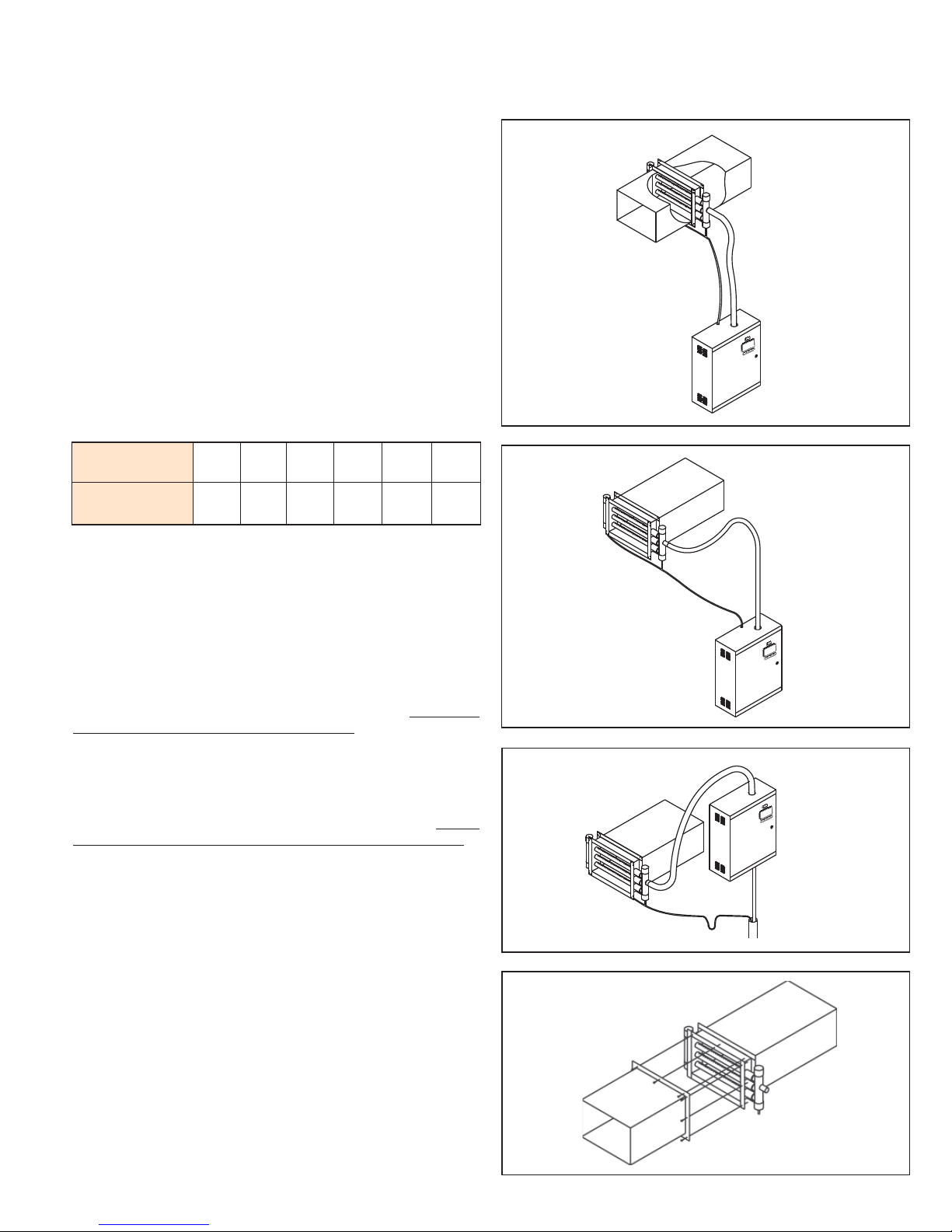
CARNES STEAM MANIFOLDS with strong galvanized flanged frames are factory
assembled to reduce installation costs.
LOCATION OF MANIFOLD
The manifold is usually located in the supply duct downstream of
the fan, heating coil, cooling coil, and/or filter. When installed in
packaged units, the manifold is to be mounted just downstream of
the fan discharge.
The non-wetting dimension is the distance necessary to prevent
condensation on any obstruction downstream from the manifold.
Condensation could occur on a cooling coil because of lower
temperatures. Steam plumes may be visible beyond the
non-wetting dimension and may moisten high efficiency filters.
Additional distance is required for installation upstream of high
efficiency filters.
Carnes humidifiers operate at 1/2 psi or less so there are
limitations on the length between the humidifier cabinet and the
steam manifold. The maximum distance depends on the static
pressure in the duct and is shown in Table 6.
MAXIMUM STEAM HOSE LENGTH (Table 6)
Duct Static
Pressure “wg”
Maximum Steam
Hose Length (Ft.)
In a typical installation, the humidifier is located below the duct
and the steam manifold is installed as shown in Figure R. The
maximum recommended length of steam hose for this type of
installation is 12 feet.
For lengths beyond 12 feet additional steps are shown in Figure
S. If sufficient headroom is not available, it is possible to install
the steam hose with an upward slope with a minimum rise of 2”
for every 12” of run.
The steam manifold may be located below the humidifier if the
installation is made in accordance with Figure T. The steam
manifold cannot be installed in a vertical duct.
The manifold has an integral mounting flange for ease of
installation. Separate mounting flanges, supplied by others, are
needed to mate with the manifold. Refer to Figure U.
If the steam manifold is used with a humidifier having two
cylinders it will require two separate lengths of steam hose. Do not
combine the outputs of two cylinders into one steam hose.
It is very important that both the steam hose and condensate
return line be installed so that sags are prevented.
If it is difficult to prevent sags, it is recommended that a copper
tube be used as a substitute. If a copper tube is used, a minimum
of one inch of insulation must be applied to prevent excessive
condensation and contact with the hot pipe. A short length of
steam hose must be used to connect the plastic cylinder in
the humidifier to the copper tube and another to connect the
copper tube to the steam manifold. It is very important to include
adequate space to move the steam hose far enough when replacing
cylinders. Any turns in the steam hose should have a minimum
radius of eight inches to prevent kinking.
Size 3/4” copper tube can be used with steam cylinders having
output rates up to 30 pounds per hour. Size 1-1/2” copper tube
should be used with steam cylinders over 30 pounds per hour.
Length restrictions shown in Table 6 also apply where copper
tube is used and any 90° elbows add approximately three feet of
equivalent length.
0 1 2 3 4 5
40 35 30 25 15 10
Figure R
Figure S
Figure T
Figure U
35
Page 36
TROUBLE SHOOTING - SYMPTOM, CAUSE AND ACTION -
Table 7
SYMPTOM CAUSE ACTION
Arcing Naturally very high conductivity water. Water may be too high in conductivity. Test water.
Drain lines restricted causing low water levels. Inspect & clean drain & tubing regularly.
Defective drain solenoid valve. Repair, clean, or replace as necessary.
Insufficient flow of incoming water. Levels low. Maintain 20 psi or above. Clean strainer, repair,
clean, or replace fill solenoid as necessary.
High back pressure in steam line. Check kinks or severe bends in steam hose. Check
system static pressure.
Excessive lengths of steam hose and/or high
static pressure.
Attempted cleaning of cylinder by flushing or
banging producing flakes causing restricted
lines.
“Service” indicator on Various. See “Service Required” page for more information
Water doesn’t fill into
cylinder (blue LED fill
indicator)
Water doesn’t fill into
cylinder (water level
doesn’t rise in cylinder)
Humidifier drains
continuously
Water in duct or spitting
from distributor pipe
All 4 basic control signals not satisfied. Make sure all control circuits are closed and the
Fill valve strainer is restricted. Remove strainer from fill valve assembly and
Fill valve is defective. Repair or replace as necessary.
24 Volts AC not coming from circuit board. Consult factory, replace circuit board.
Piece of mineral is partially blocking drain so it
will not close properly.
Drain plunger is worn out, preventing drain
valve from closing completely.
Steam hose and condensate return hose do
not have a continuous slope. Condensate
accumulates and gets pushed out of distributor.
Condensate return is blocked, kinked and
prevents proper drainage of condensate water
and accumulates in distributor pipe and pushed
out into duct.
Distributor pipe is not installed properly or
manufactured properly, not allowing for a
continuous backward slope to steam hose and
condensate hose connection.
If condensate return hose has a drop less than
12”.
Condensate return is connected to top of unit,
but a trap was installed too close to elbow, split,
turning vane, grille, or diffuser.
Shorten distance between humidifier & dispersion,
maintain proper incline in steam hose, eliminate
as many 90° or 45° bends, insulate steam line as
necessary.
Do not use solutions to clean cylinders, dispose
as necessary. Solutions could cause chemical
reactions not conducive to good operation.
regarding the problem.
humidifier is ‘On’.
clean.
Cycle drain. If it does not clear, clean as
necessary.
Repair or replace as necessary.
Improve routing of all hoses and/or install
condensate drains as necessary. Add a trap in the
steam hose in front of the distributor.
Eliminate restriction in hose and routes as required
for proper flow of condensate water.
Re-assemble, repair, or replace as necessary.
Route the condensate return to a common drain
and include a trap.
Whenever condensate hose is returned to top of
unit a trap is not required, remove it. Distributor
pipe must be a minimum of 6 feet upstream from
elbows, grilles, etc. If temperature in the in duct
is 60°F or lower the distance should be 10 feet.
If distance, as mentioned, is not possible, a drain
pan may be required. If the air in the duct cannot
hold the volume of steam, the only recourse is to
reduce the maximum output of the unit. If very
short absorption distances are required, a short
absorption manifold can be installed.
36
Page 37
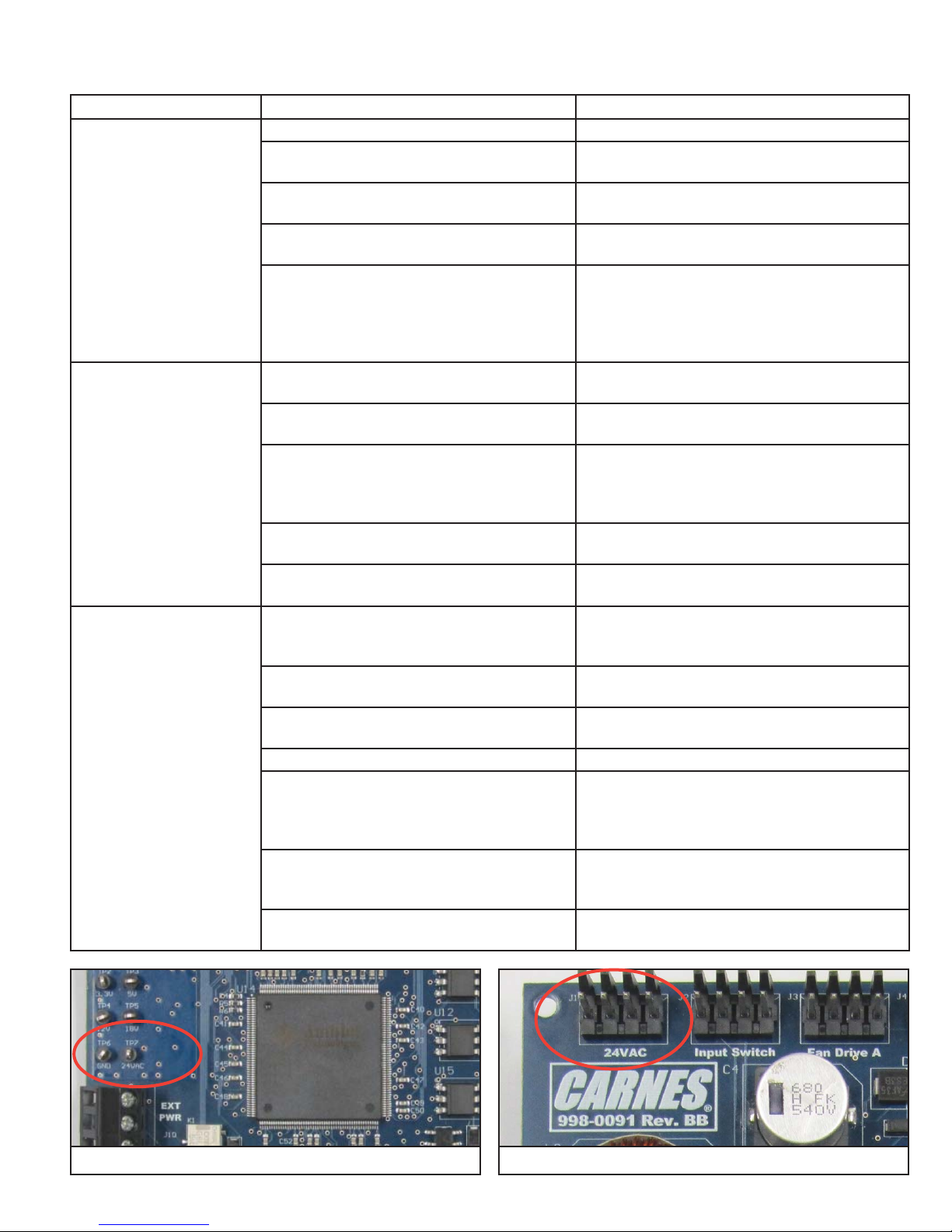
TROUBLE SHOOTING - SYMPTOM, CAUSE AND ACTION
(Continued)
SYMPTOM CAUSE ACTION
No LCD display The LCD has been dimmed. Touch LCD screen.
Voltage to the humidifier is not that which is
required per rating label.
3 phase voltage but not all legs have power. Check electrical connections and make necessary
Internal or external circuit breakers are not
closed.
24VAC supply to circuit board is not available. Make sure the protection on the transformer
Humidifier unable to
reach maximum output
or required setpoint
LCD not on Verify that voltage being supplied to the humidifier
Capacity of unit is too low. Determine proper load calculation and capacity of
Too high of a system static pressure. Supply air system must be evaluated if static
Back pressure in steam hose is too high. Check for the following: too long of steam line runs,
Foaming. Remove impurities inside the cylinder. If cleaning
Wrong cylinder. Make sure proper cylinder and configuration is
Change humidifier or make necessary changes to
confirm compatibility.
repairs or hook ups.
Close all circuit breakers.
is not tripped (fuse or breaker). Confirm the
required 24VAC is leaving transformer. Make sure
connection to circuit board at J1 is intact. If
situation does not resolve, replace circuit board.
humidifier. Use properly sized unit.
pressure is too high. Locate and correct issue.
sags, dips, horizontal runs not allowing for proper
condensate removal, improper sloping of steam
lines and condensate line.
of cylinder was attempted, throw away.
used.
is the same as that listed on the rating label on the
front left hand corner of cabinet.
If humidifier is 3 phase, verify that all legs have
power.
If the humidifier has optional internal circuit
breakers, they must be on.
Verify LCD is not in dimmed mode by touching it.
Verify that 24VAC is being supplied by the
voltage transformer by taking voltage reading
between TP6 and TP7 (Photo L). Check the
connection at J1 (Photo M).
If 24VAC is not present reset the overload
protection (breaker or fuse) located on the
transformer.
If 24VAC is present, the circuit board may be
defective.
Photo L
Photo M
37
Page 38
TROUBLE SHOOTING - SYMPTOM, CAUSE AND ACTION
(Continued)
SYMPTOM CAUSE ACTION
Water doesn’t fill into
cylinder
Drains continuously The most common cause is to have a piece
Confirm that indicators for the four basic controls
all have green checkmarks in the “Steam” menu,
and the humidifier is switched ‘On’.
If all four control requirements are checked green,
consult the “Controls” section of the IOM.
If all four control requirements are checked green,
and the ‘Steam’ indicator is not red, check the
service required page for a possible shutdown
scenario.
If no service required information is available,
check the Fill Valve indicator (the blue LED on the
front). If the LED is on, check for 24VAC at the coil
of the fill valve. If 24VAC is present water should
be flowing if water is available. Be sure all shut off
valves ahead of the humidifier are open.
If water is available, check the fill valve strainer
for sediment. The strainer may be checked by
removing the plastic nut from input side of the valve
and reaching inside the housing with a non-sharp
tool and pulling the strainer out.
If 24VAC is present and strainer is clean, the fill
valve may be defective.
If the High Water Sensor is activated, the fill valve
will not be allowed to open. In this case the blue
LED on the front panel will be off.
Make sure the drain solenoid is not partially open
due to blockage, restriction, or malfunction.
of mineral in the drain solenoid valve that prevents
the valve from closing properly. Simply cycling the
“On-Off-Drain” switch back and forth between “Off”
and “Drain” may dislodge the sediment. In extreme
cases it may be necessary to disassemble drain
lines to clean them. If mineral buildup is a reoccurring issue, make sure the “Repetitive Drain Valve”
option is enabled in the settings menu.
Check movement of the solenoid actuator to verify
that the plunger moves freely in the coil. If the coil
has overheated so that movement of the plunger is
restricted, it will require replacement of the valve.
When the Drain Valve” Red LED is lit, the circuit
board is sending 24VDC to the drain valve. If the
Red LED is on but 24VDC is present at the drain
valve, the circuit board may be defective.
38
Page 39
TROUBLE SHOOTING - SYMPTOM, CAUSE AND ACTION
SYMPTOM CAUSE ACTION
Water in the duct Note: This is usually an installation problem.
The first step is to determine whether water
is spitting from the steam distributor pipe
or if steam is condensing on some object
downstream from the steam distributor pipe.
If water is spitting from the steam distributor
pipe there may be several causes.
The steam hose and condensate return line
MUST have continuous slopes without any sags
or low areas where water could accumulate. If
water accumulates in the steam hose it may be
suddenly pushed into the distributor pipe and the
condensate return line may be unable to handle the
large volume.
Make sure that the condensate return line is not
restricted anywhere. Areas where the hose bends
or where it is tied using cable ties are often the
problem.
The distributor pipe must be installed so that the
far end of the distributor pipe is higher than the
incoming end where the condensate return
connection is located. The mounting plate on the
distributor pipes (with lengths up through 36”)
should be mounted on a plumb surface to
automatically provide proper pitch. On longer
pipes, it is necessary to support the pipe using the
bracket on the end of the pipe to insure that proper
slope is maintained.
If the condensate return line has a drop of less
than 12” from the distributor pipe to the top of the
humidifier cabinet, it may be better to route the
drain below the unit rather than connecting at the
top of the cabinet.
If the condensate return line is connected to the
fitting at the top of the humidifier cabinet, make
sure that traps have not been installed in the return
line. A trap is only needed if the return line is routed
to a separate drain and it is necessary to prevent
steam from being discharged from the line.
It may be beneficial, particularly on longer routes,
to put a trap in the steam hose right before the
distributor pipe. In this case, it is absolutely
necessary to run the condensate at the bottom of
the trap away to a separate drain.
If water is condensing on an object in the duct or
on the duct itself it will be necessary to take other
steps.
The distributor pipe must be a minimum of 6 feet
upstream from any elbow, split, coil, turning vane,
grille, or diffuser. The lower the air temperature is
in the duct the further upstream the pipe must be
located. If the air temperature is 60°F it may be
necessary to have 10 feet between the pipe and
any obstruction.
If it is not possible to have the required distance
from the distributor pipe to an obstruction a drain
pan may be required to accommodate the water.
It may be that air in the duct simply can’t hold the
volume of steam that is being added. Normally
the only practical solution is to reduce the steam
output of the humidifier, as it is usually not feasible to
increase the air temperature or quantity.
(Continued)
39
Page 40
TROUBLE SHOOTING - SYMPTOM, CAUSE AND ACTION
SYMPTOM CAUSE ACTION
Arching in the steam
cylinder
An occasional arc is not a problem. When
a cylinder is restarted after a long period of
off time arcing may occur as pieces of mineral
flake off the electrode surface. During a drain
cycle, arcing may occur if water is very low in
the cylinder. Arcing is a problem if it occurs
frequently or if it causes dark brown or
red discoloration in the cylinder. The dark
deposits are caused by deterioration of electrode
material and must be prevented. Arcing may be
caused by several conditions:
Incoming water may have high conductivity.
Conductivity, the ability to conduct current, is
measured in “micromhos”. In any electrode
type humidifier there are maximum values of
conductivity that may be used in the humidifier. It
is very unusual for any naturally occurring water
to have conductivity that is too high for operation.
It is recommended that water conductivity be
less than 900 micromhos. If water is treated by a
water softener its conductivity will be higher than
untreated water. As it is boiled away its
conductivity also increases at a higher rate than
untreated water. Softened water may be too high
in conductivity to operate without arcing.
Drain lines within the humidifier that have become
restricted by mineral deposits prevent proper drain
rates. This causes minerals to concentrate inside
the cylinder, which in turn causes low water levels.
Low water levels cause arcing. Drain lines should
be inspected when cylinders are changed and
thoroughly cleaned if necessary.
A defective drain solenoid valve will prevent proper
draining. The solenoid should be checked to verify
that it moves freely when 24VDC is applied to the
coil. When placed in the “Drain” position, both the
drain and fill valves open and it is very important
the water level falls in the cylinder.
Insufficient flow of incoming fresh water will cause
arcing by causing low water levels. Since an
automatic drain is not initiated until setpoint is
reached, a drain will not occur if the flow rate is
too low. Therefore, if low water pressure at the
humidifier (below 20 psi) or a clogged water
strainer restricts the flow of water, arcing will result.
High back pressure, which can be caused by an
obstruction in the steam hose, prevents fresh
water from entering the cylinder and results in
arcing. Care must be taken to prevent kinking of
steam hose when making bends.
Excessive lengths of steam hose in conjunction
with high duct static pressures cause low water
levels and arcing.
Frequent cleaning of the steam cylinder by
removing and flushing or by striking the side
of the cylinder potentially dislodges flakes that
can build up a “dam” in the drain lines. It is not
recommended that the cylinder be removed except
for replacement.
Chemicals should never be used to attempt
to prevent mineral build up in the cylinder or
to dissolve minerals that accumulate.
Chemical treatment may affect conductivity.
Only untreated tap water is recommended for
use in the humidifier.
(Continued)
40
Page 41
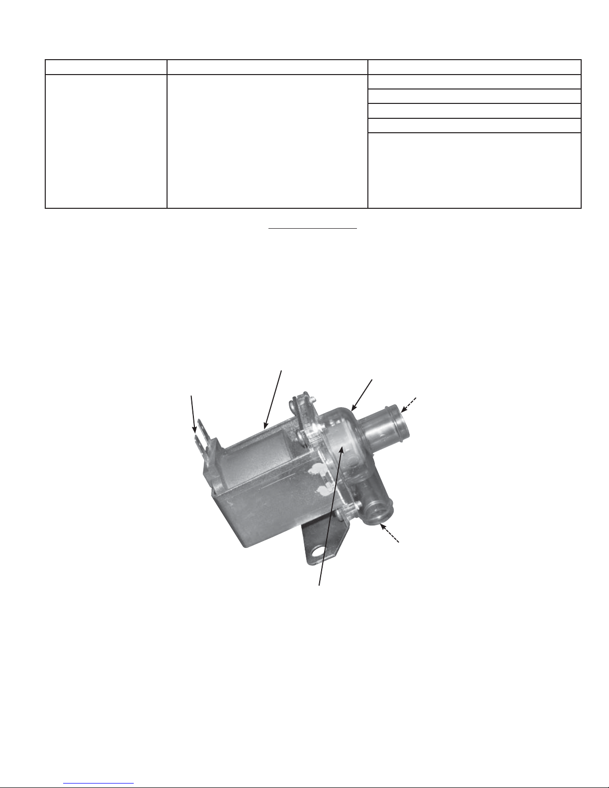
TROUBLE SHOOTING - SYMPTOM, CAUSE AND ACTION
(Continued)
SYMPTOM CAUSE ACTION
Foaming Foaming is usually due to foreign matter or
impurities getting into the cylinder through
normal water supply. Detergents, cleaning
agents used to clean dirty cylinders (cylinders
are not to be cleaned, but to be disposed
of at end of cylinder life), and water issues
precipitated by very slow or fast drain cycles.
It is important to note that when foam is
generated it is as conductive as the conditioned
water and could, if circumstances are right,
force a high water level situation.
Clean all water lines, replace if necessary.
Replace cylinder.
Reduce softening mix or concentration.
Increase water volume by correcting drain issues.
Changing cylinder, but with a different electrode
configuration to accommodate the water condition.
WATER CONTROL
The water contained in the cylinder must be controlled, in order for the humidifier to function properly. The fill and
drain rates must be maintained. Filling too quickly can cause over-current and automatic shutdown, circuit breaker
tripping or blown fuses. Filling too slowly can cause insufficient steam output or insufficient humidity levels. Water supply
pressure should be between 30 and 80 psig, ideally 55 to 60 psig. Draining too quickly can cause dangerous arcing and
electrode corrosion. Draining too slowly can cause over-concentration and malfunction due to foaming. These are just some
examples of what can go wrong if the fill and drain rates are not controlled and maintained.
24V DC Coil
Terminals
Valve Shown In
Normally Closed
Position
Solenoid Valve
Clear Plastic End Cap,
Dependent on Model, Could
Be In 3 Different Positions
Must Move Freely,
Clean As Necessary
Water
In - From
Cylinder
Fitting
Water Out,
Into Drain
41
Page 42

HUMIDIFIER OPERATIONAL SPECIFICATIONS:
1. Provide self-contained electronically controlled steam generating
humidifiers of the size(s) shown on plans as manufactured by
Carnes Company, Verona, WI.
2. Carnes Humidifiers shall have the capacity to operate at 115, 208,
230, 277, 380, 415, 460 and 575 volt (or nominal value), 60 or
50 hz (cycle), single or 3 phase power. Specific combination of
maximum output, voltage and phase for order application
determined by electrical data chart.
3. The humidifier(s) shall be UL and cUL listed.
4. The humidifier(s) shall have a total Color “True Touchscreen” user
interface. Features:
a. True Touchscreen navigation for all aspects of operation and
information access.
b. Cylinder life counter for hours of operation. Found by accessing
the “Settings” button.
c. With Fan Distribution Unit, there is a fan speed Slide Bar
control with CFM indication. Found by accessing Settings button.
d. “Help” screen button.
e. “Service Required” button and indicator and corresponding
screen explaining service issues and possible troubleshooting
tips.
f. “Dim LCD” feature button.
g. “Settings” button - where all operational values can be set.
h. “Setpoints” button - target steam output of the humidifier.
5. Steam shall be generated from tap water or softened water (see
factory representative) in a factory sealed cylinder containing
electrodes. Cylinders shall not require setting of electrode spacing,
cleaning or maintenance and shall be of the disposable type.
6. The humidifier(s) shall include an automatic drain cycle controlled
electronically to maximize energy and water usage efficiency.
Drain cycle shall adapt to variations in water conditions (high/low
conductivity and high/low hardness) and not require manual setting.
There is also a default setting for a pulsing drain action to assist in
keeping drain lines open.
7. In the event of over-current, the humidifier shall signal that a fault
condition exists by a message on the touchscreen.
Option: Humidifier(s) shall also include secondary magnetic
overload switches (circuit breakers) that shall be manually
resettable and shall be of the type that positively disconnects power
to the steam cylinder.
8. Humidifier(s) shall include a door interlock safety switch to
disconnect power to steam cylinder(s) when cabinet door is opened.
9. The system shall include one steam distributor pipe for each
steam generating cylinder mounting in the duct as shown
on the plans. Steam distributing pipe(s) shall be of corrosion
resistant design (stainless steel) and be designed to provide uniform
distribution over the entire length of the pipe.
Option: Supply and install remote (or humidifier mounted) fan
distribution units to discharge steam directly into the conditioned
space.
Provide the following components:
a. Three 12VDC fans operated by the circuit board.
b. Integral steam manifold trap.
b. Remote mounted on/off, proportional control humidistat.
Option: When plans call for a specific short absorption distance
from dispersion system, a multi-tube Short Absorption Manifold
is available sized specifically to duct dimensions, with horizontal
stainless steel cross tubes and vertical headers.
10. The system shall include flexible hose to connect the steam cylinder(s) to the steam distributor pipe(s). A separate condensate return
line shall return condensate to the humidifier for reuse to minimize
consumption. If due to specific routing issues or application of unit,
condensate line cannot run back to unit, the line can go directly to
the common drain, and the addition of a “circle” or “U” trap will be
required (see IOM). Long distances from unit to common drain can
be accommodated with accessory option Water Pump (HXWA).
Hard tubing can be used for Steam Hose and Condensate Return to
prevent sags, restrictions or obstructions (see IOM), but it is recommended a minimum of 12 inches of flexible hose be used from unit
and before distributor pipe. We recommend a maximum distance of
10 feet from unit to distributor pipe(s) or short absorption manifold
and proper routing and inclination of hoses and hard tubing be
adhered to for proper, overall consistent and dependable operation.
11. The humidifier(s) shall incorporate a 1” air gap on the fill water line
to prevent backflow. It is recommended that a drain air gap fitting be
installed by a non-Carnes contractor to prevent backflow of water.
Carnes offers an air gap fitting as a purchased option.
12. The humidifier cabinet(s) shall be constructed of 304 B 20 gauge
stainless steel and shipped with a protective film. The cabinet door
shall be hinged and provided with a lock and key. The main door is
13. The humidifier(s) shall be controlled by a humidistat which operates
Option: Provide the following accessory controls:
a. Wall mounted humidistat, on/off control.
b. Wall mounted humidistat, w/ LCD combo.
c. Duct mounted humidistat, on/off control.
d. Duct mounted humidistat, proportional control.
e. Duct mounted humidistat w/digital humidity and temperature,
f. High limit duct mounted humidistat, on/off control.
g. High limit duct mounted humidistat, proportional control.
h. Pressure differential type air flow switch.
i. Paddle type air flow switch.
j. Wall or duct mounted temperature compensated, on/off or
14. External Control Signals - All Carnes humidifiers will accept
Option: CarnesLink offers the ability to monitor and control Carnes
15. The fill water line shall include a strainer to remove sediment
16. Humidifier(s) shall include a “Service Required” button (illuminated
17. Dedicated buttons with indicator lights on the steam page of the
18. The humidifier(s) electronic circuit board shall include
19. The humidifier(s) shall include a non-water contact capacitance
20. The fill solenoid valve shall open whenever the drain solenoid is
21. Humidifiers, dependent upon capacity, will have one (1) or two (2)
22. Automatic Drain of cylinder water will take place when there is a
also provided with a quick release pin for removal to provide easy
access to internals. The True Touchscreen Home Page will show a
digital LCD steam output meter calibrated in pounds of steam per
hour (kg of steam per hour selection is included as a built in option),
fill cycle, drain cycle and high water indicator lights will be visible
with the cabinet door closed.
through the circuit board. Humidifier(s) shall incorporate terminals
for connection of humidistat, air flow switch and high limit control
humidistat.
combo.
proportional control, digital display humidistat.
external DDC control signals of 0-10 volt DC. Signal to modulate the
output of humidifier. Polarity must be observed and input impedance
is 20 kilo-ohms. If 4-20 mA signal is provided a 470 ohm, 1/4 watt
resistor must be installed. Humidifiers will also accept internal (BMS)
building management system or (BAS) building automation system
signal.
humidifier(s) (“H” Series and newer) by allowing the humidifier(s)
to link to your Building Management System (BMS) using
communication protocols; BACnet® (MS/TP), Modbus® (RTU),
Metasys® (N2) and Siemens® (FLN). CarnesLink uses a
communication chip that is factory installed on our electronic
circuit board, mounted internally inside the humidifier(s) cabinet.
The electronic circuit control board has a translucent protective
conformal coating that protects the electronic components on the
board. Features include: Oxidation Resistant, Ozone Resistant,
Thermal Resistant, UV Resistant, Water Resistant, high temperature stable, low temperature stable and operational temperature
range -45°C to 200°C.
from incoming water and a flow regulating control to automatically
compensate for water pressures from 20-120 psi.
in RED) on the total “True Touchscreen” home page which shall
explain service issues and possible troubleshooting tips. The light
shall be visible with the cabinet door closed and terminals shall be
provided for remote signal. Terminals are also provided to indicate
normal operation to a remote location.
total “True Touchscreen” shall indicate status of the control humidistat, high limit humidistat, air flow switch and door interlock switch.
Operation of fill solenoid, drain solenoid, power contactor and
high water sensor shall be shown after accessing the “Component
Activity” button on the home page of the total “True Touchscreen”.
automatic controls to compensate for varying water conditions without
changing cylinders or electrode spacing. The control shall
activate the fill and drain solenoid valves to automatically maximize
efficiency. Unit will perform system self-correction procedures to
assist in preventing unit shut-down due to any fault in operational
sequence. A drain pulsing feature is included to assist in expelling
any blockage that may occur during a self-correcting drain cycle.
If self-correction procedures are unable to correct problems after
specific cycles, unit will automatically shut-down.
proximity high water sensor to prevent overfilling and loss of water.
activated, whether in automatic or manual operation, to prevent
discharge of boiling water into drainage system. Drain light shall
indicate the switch is in drain position.
cylinders for operation. If a capacity is desired of 125, 150, 175 or
200 lb./hr., the units will be equipped with two (2) cylinders, each
independently and separately controlled by their own control signal.
demand signal loss for 72-hour drain setting is turned on. Unit will
remain in stand-by in the event that a quick startup is required.
42
Page 43

HUMIDIFIER MAINTENANCE CHECKLIST:
Unit Serial #: _____________________ No. of Humidifi ers: ______________________________________________
Model #: _________________________________ Voltage: _______ V/ ___ Ph. Steam Output: _______ lb./hr.
Customer/Job: ___________________________ Address: ______________________________________________
CYLINDER/SYSTEM CHECK:
• “Service Required” warning (Cylinder Life Counter) yes no
• Fault cylinder spent yes no
(If panel displays “Service Required” warning and the warning states “Cylinder near end of life” the cylinder will need to be
replaced soon.)
• Orange LED on with high water warning yes no
(If orange LED is on with High Water Warning and cylinder is not new, cylinder may have to be replaced soon.)
• Other warnings or faults shown in display yes no
(See Troubleshooting chapter for actions to address warnings and faults if present.)
REPLACE CYLINDER:
• Drain cylinder, first with water shutoff open yes no
• Drain cylinder, next with water shutoff closed yes no
• Disconnect open, On/Off switch is off, water shut off closed yes no
• Remove cylinder yes no
• Drain valve removed/cleaned/new O-ring yes no
• Optionally added lubricating sealant to O-ring (C series only) yes no
• Drain valve installed/ground wire attached yes no
• New cylinder installed and hose clamps tightened yes no
New cylinder model # _____________________________
(Should be same as removed cylinder.)
• Cylinder plug numbers match cylinder numbers yes no
• Cylinder plugs snug and in good condition yes no
• Electrical wiring not loose and in good condition yes no
• Steam and condensate hoses in good condition/no kinks in hose yes no
• No signs of water leaking around humidifier, internal plumbing,
steam line, condensate returns yes no
• Door replaced, water shut off valve opened, On/Off switch to on,
disconnect closed yes no
• “Reset Cylinder Life Counter” in settings. (Settings password: 1212) yes no
Started by: ________________________________________ Date of Startup: ___________________
Company: ________________________________________
43
Page 44

PREVENTATIVE MAINTENANCE:
Unit Serial #: _____________________ No. of Humidifi ers: ______________________________________________
Model #: _________________________________ Voltage: _______ V/ ___ Ph. Steam Output: _______ lb./hr.
Customer/Job: ___________________________ Address: ______________________________________________
PREVENTATIVE MAINTENANCE:
RECOMMENDED MONTHLY PREVENTATIVE
MAINTENANCE FOR HUMIDIFIERS
Service contractor or maintenance agent - be prepared to:
1. Investigate and observe.
2. Recognize issues.
3. Determine procedures.
4. Implement solutions.
5. Inform customers.
Preventative maintenance is not intended to replace
quality manufacturing and assembly from the company of
origin. Products get older, wear and tear occurs, personnel
changes and simple attention to detail sometimes become
lax. Basic preventative maintenance for humidifiers should
be required follow-up for continued proper operation of
products. Preventative maintenance is a means to prevent future
costly failures. The following are recommended preventative
maintenance procedures for humidifiers on a monthly basis:
PLEASE FOLLOW ALL REQUIRED SAFETY
PROCEDURES BEFORE WORKING ON HUMIDIFIER
UNITS.
1. Visually inspect steam hose(s) and condensate hose(s)
for proper routing and installation from humidifier
unit. Prevent sags, dips, or kinks in hoses. Eliminate
horizontal runs. Make sure there is an adequate
slope up for the steam hose and slope down for the
condensate return. Correct as necessary. Recommend no
hose lengths longer than 10 feet. Refer to earlier pages
of this IOM.
2. Visually inspect steam hose and condensate
attachment to dispersion pipe or short absorption
manifold. Recommend periodic removal of dispersion
systems for inspection (restricted dispersion holes,
damage, plumb mounting, and clamping tightness).
3. Humidifier unit - inspect internal hoses for sediment build
up or degradation. Clean or replace as necessary. Also,
check tightness of hose clamps. Tighten as necessary.
4. Inspect fill valve strainer. Industrial/commercial unit fill
valve strainer is located at the connection point of the
water inlet hose to valve. Strainer is located inside the
valve at the threads. Pop out using a non-sharp tool and
inspect. Clean or replace as necessary.
5. Visually check operation of the drain solenoid valve,
smooth operation and 100% seal when normally closed. If
necessary, remove solenoid valve, disassemble and clean
or replace as necessary.
6. Visually check the cylinder for extreme amounts of
residue on the inside surface. Very high levels of water or
the unit unable to provide full capacity may be an indication
that the cylinder is at the end of its life. Do not attempt to
clean out with chemicals; do not stick screwdrivers or other
objects into cylinder to clean out sediment. These cylinders
are made to be replaced at end of life cycle. Life cycle of
a cylinder is often determined by the condition of the water
used in the unit, especially hardness, % of max output, or
run time (24/7, 8 hr./day, etc.). Refer to this IOM or main
humidifier catalog for more information.
7. Visually and manually check all wires and connections
inside the unit. Include inspecting the wire connections to
the top of the cylinder. If a red 90° connector is used, be
sure to check the inside of the connector for a set screw.
This screw needs to be checked for tightness. Make sure
control wires at the J16, J17 and J18 terminal connections,
bottom of the circuit board, are tight.
8. Monthly - remove drain air gap and check for any
sediment buildup that may block any free flow of water.
These check points for the “H” series humidifier are basic, but
significantly covers the entire unit.
Keeping a preventative maintenance record would be
recommended to show maintenance performed and any
observations made during inspection.
44
Page 45
EXTENDED SHUTDOWN/STARTING AFTER EXTENDED SHUTDOWN:
Unit Serial #: _____________________ No. of Humidifi ers: ______________________________________________
Model #: _________________________________ Voltage: _______ V/ ___ Ph. Steam Output: _______ lb./hr.
Customer/Job: ___________________________ Address: ______________________________________________
EXTENDED SHUTDOWN
During long periods of humidification downtime, the cylinder should be completely drained and emptied.
1. Manually push the On/Off rocker switch to drain.
2. Wait until the humidifier is completely drained of water.
3. Turn the On/Off rocker switch to the “OFF” position.
4. Shut off the main external power to the humidifier unit.
5. Turn the supply water off at the shut-off valve.
CARNES RECOMMENDS THAT THE CYLINDER REMAIN EMPTY DURING EXTENDED SHUTDOWN
NOTE:
!
STARTING AFTER EXTENDED SHUTDOWN
1. Inspect the humidifier for any damage. Check to make sure the mounting and installation has not been altered.
2. Turn on the main external power to the humidifier unit.
3. Turn the On/Off rocker switch to the “ON” position.
4. Review and follow the startup procedure in the IOM.
PERIODS. THIS WILL PREVENT THE POSSIBILITY OF CORROSION OF THE ELECTRODES AND
THE ACCUMULATION OF ALGAE AND BACTERIA GROWING IN THE CYLINDER.
45
Page 46
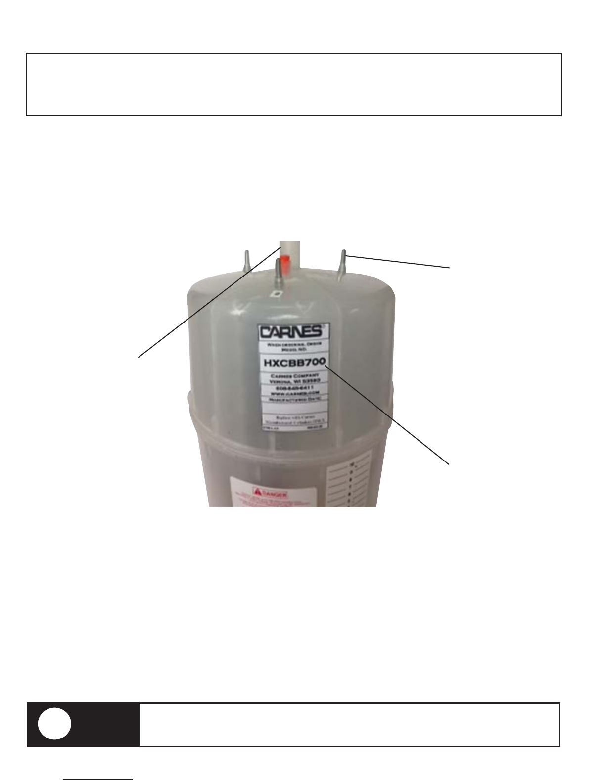
REPLACEMENT CYLINDER:
Unit Serial #: _____________________ No. of Humidifi ers: ______________________________________________
Model #: _________________________________ Voltage: _______ V/ ___ Ph. Steam Output: _______ lb./hr.
Customer/Job: ___________________________ Address: ______________________________________________
The label on the existing cylinder identifies the cylinder model. When ordering, please quote the 7, 8 or 9 digit model number
from the cylinder label. You will also need to provide the humidifier model number and serial number (located on the sticker on
the front of the unit).
Electrode Pin
Connect number coded
cylinder plugs to the
corresponding
numbered pins.
Steam Outlet
Secure steam hose
outlet with hose clamp.
Cylinder Label
This label identifies
the cylinder model and
ordering information.
CARNES RECOMMENDS THAT THE CYLINDER REMAIN EMPTY DURING EXTENDED SHUTDOWN
NOTE:
!
PERIODS. THIS WILL PREVENT THE POSSIBILITY OF CORROSION OF THE ELECTRODES AND
THE ACCUMULATION OF ALGAE AND BACTERIA GROWING IN THE CYLINDER.
46
Page 47

REMOVING THE CYLINDER:
Unit Serial #: _____________________ No. of Humidifi ers: ______________________________________________
Model #: _________________________________ Voltage: _______ V/ ___ Ph. Steam Output: _______ lb./hr.
Customer/Job: ___________________________ Address: ______________________________________________
• Disconnect power (external shut-off) before servicing.
WARNING
!
1. Completely drain the existing cylinder (flip On/Off rocker switch to “Drain).
2. Turn off water supply at the shut-off valve.
3. Turn the humidifier off (flip On/Off rocker switch to “OFF”).
4. Turn main power “Off” at the external shut-off.
5. Remove all terminal plugs from the cylinder.
6. Loosen the steam hose clamp and remove the steam hose from the cylinder.
7. (Using a flat head screwdriver) Remove the cylinder strap, keeping the cylinder in place.
8. A and B sized cylinders are threaded. Unscrew the cylinder (counter clockwise) and lift up and out.
9. C sized cylinders are seated into the brass plumbing with an O-ring. Just lift up and out.
• CAUTION: cylinder may be hot.
• Compartments contain high voltage wiring.
Fill Cup
Lock
Steam Hose Electrode Connector
Drain Valve
On-Off-Drain Switch
LCD
Door Interlock Switch
Circuit Breakers
Cylinder
Cylinder Fitting
47
Page 48
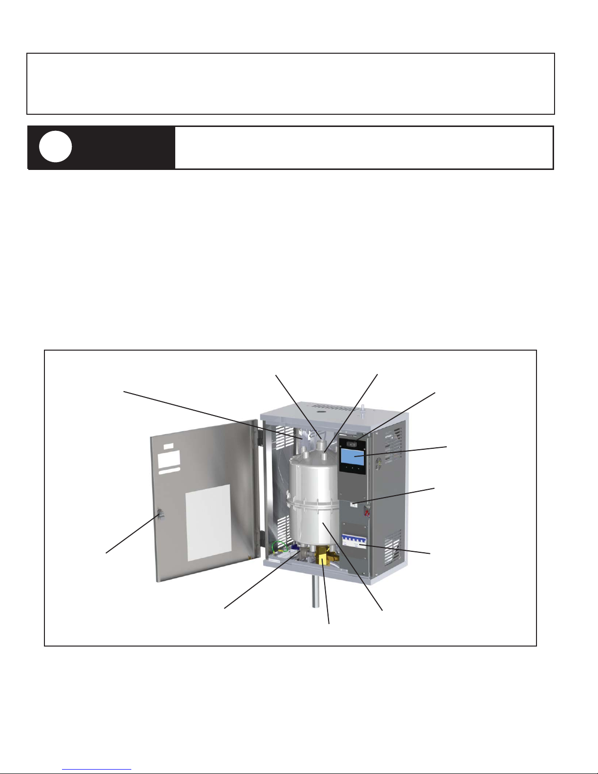
INSTALLING THE CYLINDER:
Unit Serial #: _____________________ No. of Humidifi ers: ______________________________________________
Model #: _________________________________ Voltage: _______ V/ ___ Ph. Steam Output: _______ lb./hr.
Customer/Job: ___________________________ Address: ______________________________________________
• Keep power off (external shut-off) until cylinder is in place and
!
1. Insert cylinder into brass cylinder fitting.
2. A and B style cylinders are threaded. Verify there is Teflon tape on the threads and do not over tighten.
3. C sized cylinders have no threading, verify the two O-rings are present and set the cylinder fully.
4. Secure the cylinder with the white cylinder straps (not labeled).
5. Do not over tighten as this may damage the cylinder.
6. Connect the terminal wires to the electrodes so that the numbers match those on the cylinder. Push the plugs onto the pins
to ensure the electrode plugs are firmly in place.
7. Place the steam hose onto the steam outlet and tighten the steam hose clamp.
8. Turn main power “On” at the external shut-off.
9. Turn on the water supply at the shut-off valve.
10. Turn the humidifier on (flip On/Off rocker switch to “ON”).
WARNING
reconnected.
• Compartments contain high voltage wiring.
Fill Cup
Lock
Steam Hose Electrode Connector
Drain Valve
On-Off-Drain Switch
LCD
Door Interlock Switch
Circuit Breakers
Cylinder
Cylinder Fitting
48
Page 49
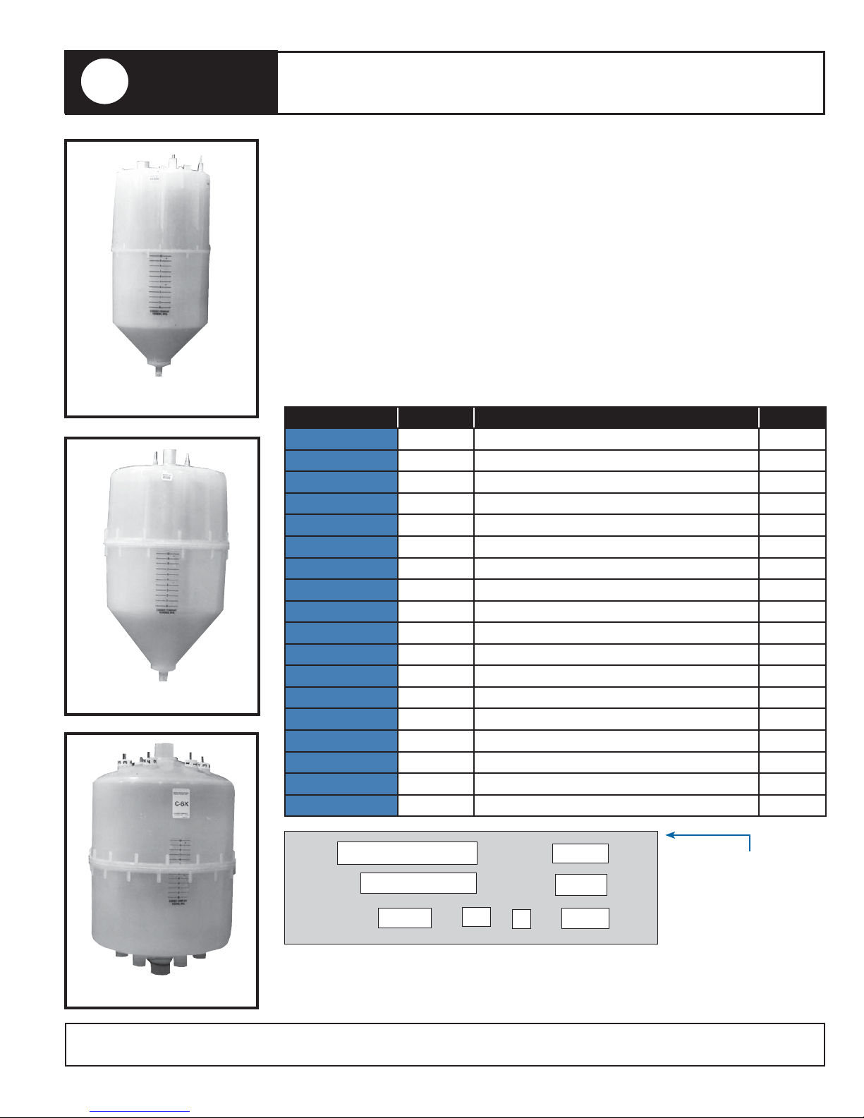
!
WARNING
“AX” Cylinder
“B” Cylinder
UNAUTHORIZED MODIFICATION OF THIS HUMIDIFIER OR USING UNAUTHORIZED
REPLACEMENT PARTS MAY CAUSE MALFUNCTION WITH RISK OF SERIOUS
PERSONAL INJURY AND WILL VOID ALL PRODUCT WARRANTIES.
REPLACEMENT CYLINDER ORDER FORM
Name: ___________________________________________________
Company: ________________________________________________
Address: _________________________________________________
City: ____________________State/Province: _____ Code: ________
Phone: __________________ Email: __________________________
Part # Cylinder Humidifi er Specifi cations Quantity
HXCBAX145 “AX” Contact Carnes Rep for more info.
HXCBAX220 “AX” 005/010 lb./hr. 120V 1 Ph.
HXCBAX380 “AX” 005/010 lb./hr. 208-277V 1 Ph.
HXCBAX500 “AX” Contact Carnes Rep for more info.
HXCBAX600 “AX” 005/010 lb./hr. 415-380V 1 Ph.
HXCBAX700 “AX” 005/010 lb./hr. 460-575V 1 Ph.
HXCBB380 “B” Contact Carnes Rep for more info.
HXCBB500 “B” 020/030 lb./hr. 208-277V 1 & 3 Ph.
HXCBB600 “B” 020/030 lb./hr. 380-415V 1 Ph.
HXCBB700 “B” 020/030 lb./hr. 460-575V 1 & 3 Ph.
HXCBC12 “C” 080/200 lb./hr. 380-575V 3 Ph.
HXCBC6F “C” Contact Carnes Rep for more info.
HXCBC6X “C” Contact Carnes Rep for more info.
HXCBC61 “C” Contact Carnes Rep for more info.
HXCBC62 “C” 030/100 lb./hr. 208-277V 1 & 3 Ph.
HXCBC63 “C” Contact Carnes Rep for more info.
HXCBC64 “C” Contact Carnes Rep for more info.
HXCBC65 “C” 030/060 lb./hr. 380-575V 1 & 3 Ph.
Cylinders can be ordered directly from your local agent. You can also fill out
this form and email it directly to Carnes at [email protected]. We will have
“C” Cylinder
“Due to ongoing research and development CARNES reserves the right to change specifications without notice.”
your agent contact you. Thank you for choosing Carnes Humidifiers.
Copyright © 2016 Carnes Company. All Rights Reserved
MODEL LBS/HR
SERIAL NO. CODE
POWER SUPPLY VAC HZ PH. AMPS
49
Requested information
is located on a label
on the outside of the
humidifier cabinet on
the lower left corner.
Page 50
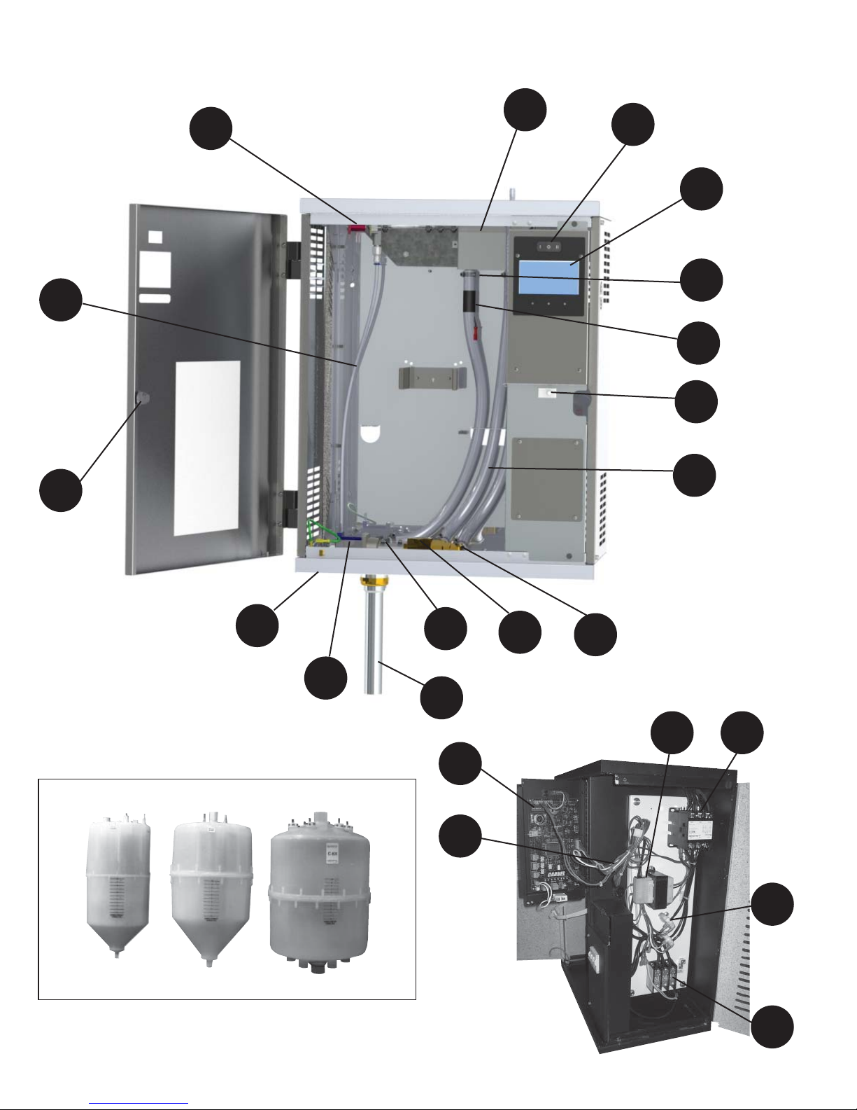
REPLACEMENT PARTS
6
11
7
2
1
9
10
24
29
21
14
SEE TABLE 2 FOR STEAM CYLINDER SELECTION
13
28
1
25
17
12
18
3 4
TYPE “AX” TYPE “B” TYPE “C”
23
22
50
Page 51
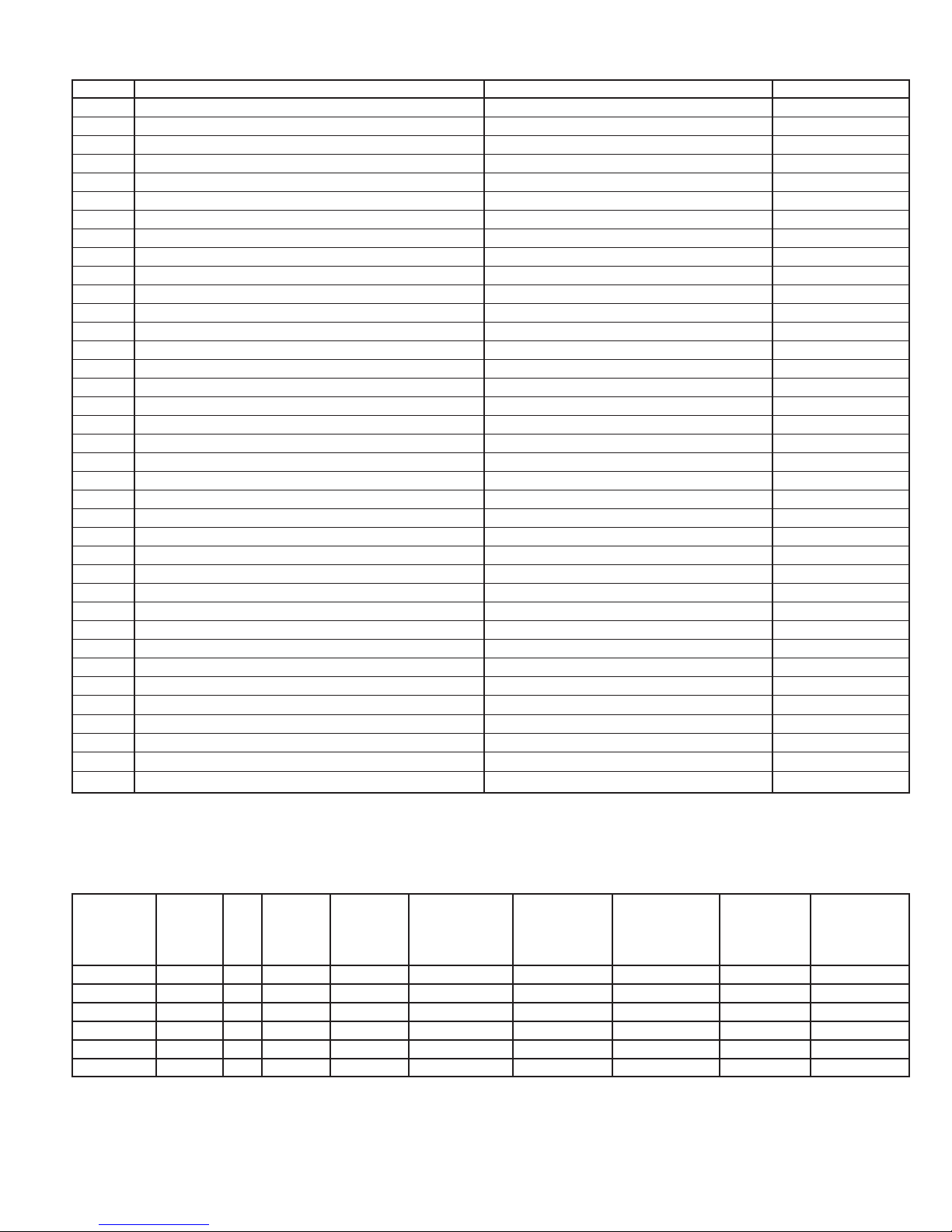
REPLACEMENT PARTS (Table 8)
Item # Description Models Where Used Part #
1 CIRCUIT BOARD WITH TOUCHSCREEN DISPLAY ALL SEE TABLE 10
2 ON-OFF-DRAIN SWITCH ALL H-999-7331
3 POWER TRANSFORMER ALL SEE TABLE 9
4 CONTACTOR ALL SEE TABLE 9
5* CIRCUIT BREAKER (optional) HT MODELS ONLY SEE TABLE 9
6 FILL SOLENOID VALVE WITH COIL AND STRAINER ALL H-999-7488
7 MOLDED FILL CUP ALL H-690-4138
8* DOOR PIVOT RELEASE ALL H-999-9143
9 METAL HOSE CLAMP ALL H-999-7165
10 HIGH WATER SENSOR SUB-ASSEMBLY ALL H-690-1355
11 WATER FILL TUBE SUB-ASSEMBLY (Single Cylinder)
11 WATER FILL TUBE SUB-ASSEMBLY (Dual Cylinder)
H_AH, H_DH, H_GH
H_HH
H-690-1672
H-690-1671
12 CLEAR HOSE 5/8” ID ALL HXLA
13* PLASTIC ELBOW 5/8” HOSE TO 5/8” HOSE ALL H-999-9690
14 DRAIN SOLENOID VALVE H_GH H-999-7448
14 DRAIN SOLENOID VALVE H_HH H-690-1091 R. H.
14 DRAIN SOLENOID VALVE
H_AH, H_DH, H_HH
H-690-1092 L. H.
17 “AX” CYLINDER FITTING H_AH H-998-5703
17 “B” CYLINDER FITTING H_DH H-998-5715
17 “C” CYLINDER FITTING H_GH, H_HH H-998-5716
18
BRASS ELBOW 3/8” NPT TO 5/8” HOSE BARB
ALL H-999-3869
19* PLASTIC “T” 5/8” HOSE TO 5/8” HOSE TO 5/8” HOSE ALL H-999-3863
20* TERMINAL CONNECTOR WITH WIRE** ALL SEE TABLE 9
21 WATER INLET FITTING ALL H-999-4055
22 POWER DISTRIBUTION BLOCK ALL SEE TABLE 9
23 CURRENT SENSING TRANSFORMER ALL H-999-9429
24 DOOR INTERLOCK SWITCH ALL H-801-7801
25 LOW VOLTAGE WIRING HARNESS
25 LOW VOLTAGE WIRING HARNESS
H_AH, H_DH, H_GH (purchased after 9/1/15)
H_AH, H_DH, H_GH (purchased prior to 9/1/15)
H-998-7024
H-998-7025
25 LOW VOLTAGE WIRING HARNESS H_HH H-998-7029
26* STRAIGHT BRASS FITTING 3/8” NPT WITH BARB H_AH H-999-4058
27* PLASTIC “U” TUBE H_AH, H_DH, H_GH H-998-5699
27* PLASTIC ELBOW H_HH H-998-5700
28* DRAIN FITTING TUBE ALL H-999-6469
29 DOOR LOCK WITH KEY ALL H-999-9141
30* FLEXIBLE CLEAR PLASTIC 5/8” ELBOW ALL H-999-9833
31* FLEXIBLE CLEAR PLASTIC 5/8” “U” TUBE ALL H-999-9834
* = Not Shown
REPLACEMENT PARTS (Table 9)
Max.
Model
Lb./Hr. Ph. Volts
H_AHA 5 1 120 AX220 998-9537 999-7389 690-3019 999-7406 999-8035
H_AHB 5 1 208 AX380 998-9537 999-7389 690-3019 999-7405 999-8035
H_AHD 5 1 230 AX380 998-9537 999-7389 690-3019 999-7406 999-8035
H_AHF 5 1 277 AX380 998-9535 999-7389 690-3019 999-7405 999-8035
H_AHL 5 1 380 AX600 998-9535 999-7389 690-3019 999-7405 999-8035
H_AHQ 5 1 415 AX600 998-9535 999-7389 690-3019 999-7405 999-8035
Steam
Cylinder
Power
Transformer
Item #3
51
Contactor
Item #4
Terminal
Connector
with Wire*
Item #20
Circuit
Breaker
Item #5
Power
Distribution
Block
Item #22
Page 52
REPLACEMENT PARTS (Table 9) - Continued
Power
Model
Max.
Lb./Hr. Ph. Volts
Steam
Cylinder
Transformer
Item #3
Contactor
Item #4
H_AHM 5 1 460 AX700 998-9537 999-7389 690-3019 999-7405 999-8035
H_AHN 5 1 575 AX700 998-9539 999-7389 690-3019 999-7412 999-8035
H_AHA 10 1 120 AX220 998-9537 999-7480 690-3019 999-7409 999-8035
H_AHB 10 1 208 AX380 998-9537 999-7389 690-3019 999-7407 999-8035
H_AHD 10 1 230 AX380 998-9537 999-7389 690-3019 999-7407 999-8035
H_AHF 10 1 277 AX380 998-9535 999-7389 690-3019 999-7406 999-8035
H_AHL 10 1 380 AX600 998-9535 999-7389 690-3019 999-7405 999-8035
H_AHQ 10 1 415 AX600 998-9535 999-7389 690-3019 999-7405 999-8035
H_AHM 10 1 460 AX700 998-9537 999-7389 690-3019 999-7405 999-8035
H_AHN 10 1 575 AX700 998-9539 999-7389 690-3019 999-7412 999-8035
H_DHB 20 1 208 B380 998-9537 999-7480 690-3019 999-7410 999-8035
H_DHD 20 1 230 B380 998-9537 999-7480 690-3019 999-7407 999-8035
H_DHF 20 1 277 B380 998-9535 999-7389 690-3019 999-7409 999-8035
H_DHL 20 1 380 B600 998-9535 999-7389 690-3019 999-7408 999-8035
H_DHQ 20 1 415 B600 998-9535 999-7389 690-3019 999-7407 999-8035
H_DHM 20 1 460 B700 998-9537 999-7389 690-3019 999-7406 999-8035
H_DHN 20 1 575 B700 998-9539 999-7389 690-3019 999-7412 999-8035
H_DHC 20 3 208 B500 998-9537 999-7389 690-3019 999-7407 999-8035
H_DHE 20 3 230 B500 998-9537 999-7389 690-3019 999-7407 999-8035
H_DHT 20 3 380 B600 998-9535 999-7389 690-3019 999-7405 999-8035
H_DHW 20 3 415 B600 998-9535 999-7389 690-3019 999-7405 999-8035
H_DHG 20 3 460 B700 998-9537 999-7389 690-3019 999-7405 999-8035
H_DHH 20 3 575 B700 998-9539 999-7389 690-3019 999-7412 999-8035
H_DHC 30 3 208 B500 998-9537 999-7480 690-3019 999-7409 999-8035
H_DHE 30 3 230 B500 998-9537 999-7389 690-3019 999-7409 999-8035
H_DHT 30 3 380 B600 998-9535 999-7389 690-3019 999-7407 999-8035
H_DHW 30 3 415 B600 998-9535 999-7389 690-3019 999-7406 999-8035
H_DHG 30 3 460 B700 998-9537 999-7389 690-3019 999-7406 999-8035
H_DHH 30 3 575 B700 998-9539 999-7389 690-3019 999-7412 999-8035
H_GHB
*
30 1 208 C62 998-9537 999-7389 (2) 690-3019 999-7401 999-8035
H_GHD 30 1 230 C62 998-9537 999-7480 690-3046 999-7411 999-8035
H_GHF 30 1 277 C62 998-9535 999-7480 690-3046 999-7410 999-8035
H_GHL 30 1 380 C62 998-9535 999-7480 690-3046 999-7409 999-8035
H_GHQ 30 1 415 C62 998-9535 999-7389 690-3019 999-7409 999-8035
H_GHM 30 1 460 C62 998-9537 999-7389 690-3019 999-7408 999-8035
H_GHN 30 1 575 C62 998-9539 999-7389 690-3019 999-7414 999-8035
H_GHC 40 3 208 C62 998-9537 999-7480 690-3046 999-7411 999-8035
H_GHE 40 3 230 C62 998-9537 999-7480 690-3046 999-7410 999-8035
H_GHT 40 3 380 C65 998-9535 999-7389 690-3019 999-7408 999-8035
H_GHW 40 3 415 C65 998-9535 999-7389 690-3019 999-7408 999-8035
H_GHG 40 3 460 C65 998-9537 999-7389 690-3019 999-7407 999-8035
H_GHH 40 3 575 C65 998-9539 999-7389 690-3019 999-7413 999-8035
H_GHC 50 3 208 C62 998-9537 999-7389 (2) 690-3019 999-7409 (2) 999-8035
H_GHE 50 3 230 C62 998-9537 999-7480 690-3046 999-7401 999-8035
H_GHT 50 3 380 C65 998-9535 999-7480 690-3046 999-7409 999-8035
H_GHW 50 3 415 C65 998-9535 999-7389 690-3019 999-7409 999-8035
H_GHG 50 3 460 C65 998-9537 999-7389 690-3019 999-7408 999-8035
H_GHH 50 3 575 C65 998-9539 999-7389 690-3019 999-7414 999-8035
H_GHC
H_GHE
*
60 3 208 C62 998-9537 999-7480 (2) 690-3046 999-7401 (2) 999-8035
*
60 3 230 C62 998-9537 999-7389 (2) 690-3019 999-7401 (2) 999-8035
H_GHT 60 3 380 C65 998-9535 999-7480 690-3046 999-7410 999-8035
H_GHW 60 3 415 C65 998-9535 999-7480 690-3046 999-7409 999-8035
H_GHG 60 3 460 C65 998-9537 999-7389 690-3019 999-7409 999-8035
*H-690-3019 INCLUDES #10 WIRE. FOR RED CONNECTOR ONLY ORDER H-998-1256.
H-690-3046 INCLUDES #8 WIRE. BLACK CONNECTOR ONLY IS NOT AVAILABLE.
* = Circuit Breaker is REQUIRED per NEC 48 amp guidelines.
52
Terminal
Connector
with Wire*
Item #20
Circuit
Breaker
Item #5
Power
Distribution
Block
Item #22
Page 53
REPLACEMENT PARTS (Table 9) - Continued
Model
Max.
Lb/Hr Ph. Volts Code
Steam
Cylinder
Power
Transformer
Item #3
Contactor
Item #4
Terminal
Connector
with Wire*
Item #20
Circuit
Breaker
Item #5
Power
Distribution
Block
Item #22
H_GHH 60 3 575 7060 C65 998-9539 999-7389 690-3019 999-7414 999-8035
H_GHC*80 3 208 2080 C62 998-9537 999-7480 (2) 690-3046 999-7403 (2) 999-8035
H_GHE
*
80 3 230 4080 C62 998-9537 999-7480 (2) 690-3046 999-7402 (2) 999-8035
H_GHT 80 3 380 3380 C12 998-9535 999-7480 690-3046 999-7411 999-8035
H_GHW 80 3 415 4380 C12 998-9535 999-7480 690-3046 999-7411 999-8035
H_GHG 80 3 460 6080 C12 998-9537 999-7480 690-3046 999-7410 999-8035
H_GHH 80 3 575 7080 C12 998-9539 999-7389 690-3019 999-7415 999-8035
H_GHC*100 3 208 2100 C62 998-9537 999-7480 (2) 690-3046 999-7403 (2) 999-8035
H_GHE*100 3 230 4100 C62 998-9537 999-7480 (2) 690-3046 999-7403 (2) 999-8035
H_GHT*100 3 380 3300 C12 998-9535 999-7389 (2) 690-3046
Contact Factory
999-8035
H_GHW 100 3 415 4300 C12 998-9535 999-7389 (2) 690-3019 999-7409 (2) 999-8035
H_GHG 100 3 460 6100 C12 998-9537 999-7480 690-3046 999-7411 999-8035
H_GHH 100 3 575 7100 C12 998-9539 999-7480 690-3046 999-7416 999-8035
H_HHC*125 3 208 2125 C62 (2) 998-9537 999-7480 (4) 690-3046 999-7401 (4) 999-8035
H_HHE*125 3 230 4125 C62 (2) 998-9537 999-7480 (4) 690-3046 999-7401 (4) 999-9524
H_HHT*125 3 380 3325 C12 (2) 998-9535 999-7480 (2) 690-3046 999-7402 (2) 999-8035
H_HHW*125 3 415 4325 C12 (2) 998-9535 999-7480 (2) 690-3046 999-7402 (2) 999-8035
H_HHG*125 3 460 6125 C12 (2) 998-9537 999-7480 (2) 690-3046 999-7401 (2) 999-8035
H_HHH 125 3 575 7125 C12 (2) 998-9539 999-7389 (2) 690-3019 999-7414 (2) 999-8035
H_HHC*150 3 208 2150 C62 (2) 998-9537 999-7480 (4) 690-3046 999-7402 (4) 999-9524
H_HHE*150 3 230 4150 C62 (2) 998-9538 999-7480 (4) 690-3046 999-7401 (4) 999-9524
H_HHT*150 3 380 3315 C12 (2) 998-9535 999-7480 (2) 690-3046 999-7402 (2) 999-8035
H_HHW*150 3 415 4315 C12 (2) 998-9535 999-7480 (2) 690-3046 999-7402 (2) 999-8035
H_HHG*150 3 480 6150 C12 (2) 998-9537 999-7480 (2) 690-3046 999-7402 (2) 999-8035
H_HHH*150 3 575 7150 C12 (2) 998-9539 999-7389 (2) 690-3019 999-7414 (2) 9998-8035
H_HHC*175 3 208 2175 C62 (2) 998-9537 999-7480 (4) 690-3046 999-7403 (4) 999-9524
H_HHE*175 3 230 4175 C62 (2) 998-9537 999-7480 (4) 690-3046 999-7403 (4) 999-9524
H_HHT*175 3 380 3317 C12 (2) 998-9535 999-7480 (4) 690-3046
Contact Factory
999-9524
H_HHW*175 3 415 4317 C12 (2) 998-9535 999-7480 (2) 690-3046 999-7403 (2) 999-9524
H_HHG*175 3 460 6175 C12 (2) 998-9537 999-7480 (2) 690-3046 999-7403 (2) 999-8035
H_HHH*175 3 575 7175 C12 (2) 998-9539 999-7480 (2) 690-3046 999-7416 (2) 999-8035
H_HHC*200 3 208 2200 C62 (2) 998-9537 999-7480 (4) 690-3046 999-7403 (4) 999-9524
H_HHE*200 3 230 4200 C62 (2) 998-9537 999-7480 (4) 690-3046 999-7403 (4) 999-9524
H_HHT*200 3 380 3321 C12 (2) 998-9535 999-7480 (4) 690-3046
H_HHW*200 3 415 4321 C12 (2) 998-9535 999-7480 (4) 690-3046
Contact Factory
Contact Factory
999-9524
999-9524
H_HHG*200 3 460 6200 C12 (2) 998-9537 999-7480 (2) 690-3046 999-7403 (2) 999-8035
H_HHH*200 3 575 7200 C12 (2) 998-9539 999-7480 (2) 690-3046 999-7416 (2) 999-8035
* = Circuit Breaker is REQUIRED per NEC 48 amp guidelines.
CIRCUIT BOARD (Table 10)
Model Series Type Power Output Capacity Options
1 2 3 4 5 6 7 8 9 10
H X N A C G 0 5 0
H - Humidifier
X - Accessory
Design Board Nominal Steam
N - Circuit Board
A - H690-0080
B - H690-0106
C - H690-0107
VOLTAGE
A - 115V, 1 Ph.
B - 208V, 1 Ph.
C - 208 V, 3 Ph.
D - 230V, 1 Ph.
E - 230V, 3 Ph.
F - 277V, 1 Ph.
G - 460V, 3 Ph.
H - 575V, 3 Ph.
M - 460V, 1 Ph.
N - 575V, 1 Ph.
53
Lb/Hr
005 - 5#/Hr
010 - 10#/Hr
020 - 20#/Hr
030 - 30#/Hr
040 - 40#/Hr
050 - 50#/Hr
060 - 60#/Hr
080 - 80#/Hr
100 - 100#/Hr
125 - 125#/Hr
150 - 150#/Hr
175 - 175#/Hr
200 - 200#/Hr
A
A - BACnet MS/TP
C - Modbus RTU
D - Metasys N2
E - Siemens FLN
Page 54

WARRANTY
Seller warrants products manufactured by it and supplied hereunder to be free from defects in materials and
workmanship under normal use and proper maintenance for a period of twelve months from date of shipment. If within
such period any such products shall be proved to Seller’s reasonable satisfaction to be defective, such products shall be
repaired or replaced at Seller’s option. Seller’s obligation and Buyer’s exclusive remedy hereunder shall be limited to such
repair and replacement and shall be conditioned upon Seller’s receiving written notice of any alleged defects no later than
10 days after its discovery within the warranty period and, at Seller’s option, the return of such products to Seller, f.o.b. its
factory, when such return is feasible. Seller reserves the right to satisfy its warranty obligation in full by reimbursing Buyer
for all payments it makes hereunder, and Buyer shall thereupon return the products to Seller. Seller shall have the right
to remedy such defects.
THE FOREGOING WARRANTIES ARE EXCLUSIVE AND IN LIEU OF ALL OTHER EXPRESS AND IMPLIED WARRANTIES
(EXCEPT TO TITLE) INCLUDING BUT NOT LIMITED TO IMPLIED WARRANTIES OF MERCHANTABILITY, FITNESS
FOR A PARTICULAR PURPOSE, PERFORMANCE, OR OTHERWISE, and in no event shall the Seller be liable for claims
(based upon breach of express or implied warranty, negligence, product liability, or otherwise) for any other damages,
whether direct, immediate, incidental, foreseeable, consequential, or special.
54
Page 55

55
Page 56

56
 Loading...