

Page 1
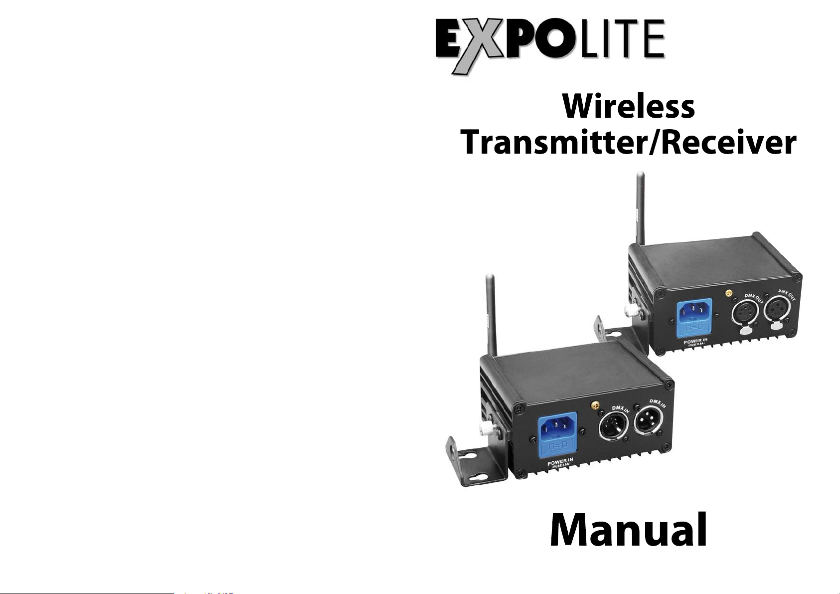
Wireless
Transmitter/Receiver
Manual
Page 2

T
ABLE OF CONTENTS
PART 1 PRODUCT SPECIFICATIONS............................................1.
1.1-- ......................................................................1.W-DMX PRODUCTS
1.2--PHYSICAL DIMENSIONS..................................... .........................1.
NOTES
PART 2 INSTALLATION................................................................2.
2.1-- .......................................... .................. ...............2.TRANSMITTER
2.2-- .................................................................... ........... ...3.RECEIVER
2.3-- ...................................... .............. 4.POINT-TO-POINT OPERATION
2.3-- ................... ..... ................. 4.POINT-TO-MULTIPOINT OPERATION
Page 3
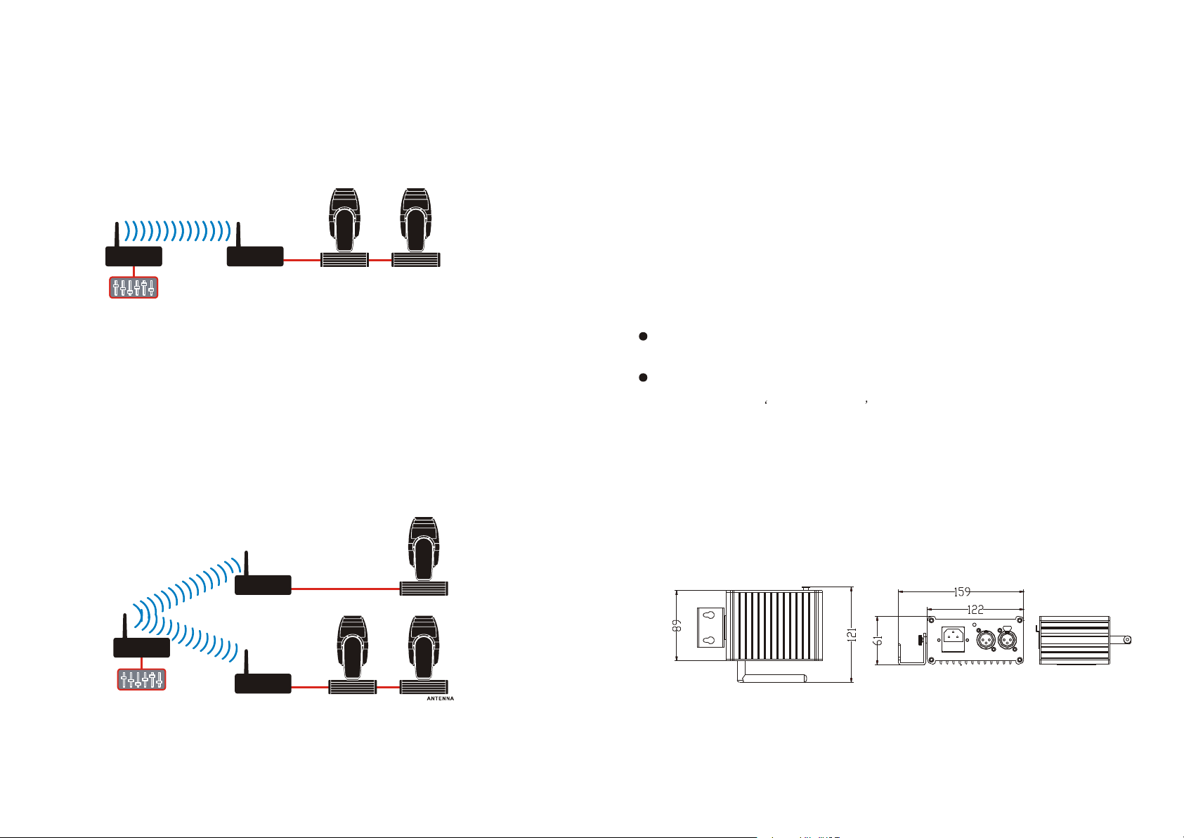
2.3 POINT-TO-POINT OPERATION
1 PRODUCT SPECIFICATIONS
Point-to-point systems are used when you want to send wireless DMX data from a console
to a single receiver. As the receiver accepts all 512 DMX channels from the transmitter you
can easily daisy chain more fixtures by cable from the original fixture that is wirelessly
connected.
Tx Rx
Tx Rx
2.4 POINT-TO-MULTIPOINT OPERATION
A multipoint W-DMX system can support up to 512 individual receivers responding to a single
W-DMX transmitter. All receivers in a multipoint system will listen only to the designated
transmitter and they will all receive the full 512 channels of the DMX universe. This makes it
straightforward to connect single fixtures or daisy-chained groups of fixtures to any of the
receivers in the system.
1.1 W-DMX products
The W-DMX system lies at the heart of every one of our products. The W-DMX radio card is
specifically engineered by Wireless Solution Sweden AB to provide the same quality, reliability and
perform-ance as any hardwired DMX data link. In fact W-DMX gives you greater freedom to create
reliable point-to-point and point-to-multipoint installations over large distances.
W-DMX is unique in its use of certain advanced radio techniques which are more often found in
mobile phone and military com-munications. Rather than using fixed frequency channels, W-DMX
uses adaptive frequency hopping technology to continually check for interference and to rapidly
move operation over to clear radio channels. This occurs one thousand times every second and is
used in combination with another advanced technique (called time division multiple access) which
makes the most efficient use of every visited frequency channel.
The advantage of such technology will quickly become clear to you: consistent and wide ranging
control of your lighting systems over potentially great distances. Indeed, you may actually find that
It is all too easy to take W-DMX for granted, for two main reasons:
Firstly, the complex communication protocols are fully auto-mated and concealed from view - you
just plug-and-play, the units do all the hard work.
Secondly, from the DMX connector of one unit to the DMX connector of another, the W-DMX
system is totally transparent. W-DMX fully adheres to the USITT DMX-512 standard and can
justifiably be called a wireless DMX cable .
These are the reasons why in every independent comparison with competing products, W-DMX
units continually take first prize for distance covered, resilience against interference and ease of
installation.
1.2 PHYSICAL DIMENSIONS
1.2.1 DIMENSIONS:204.5X196X174.5mm
Rx
Tx
Rx
1.2.2 WEIGHT:0.53KG
14
Page 4
2 INSTALLATION
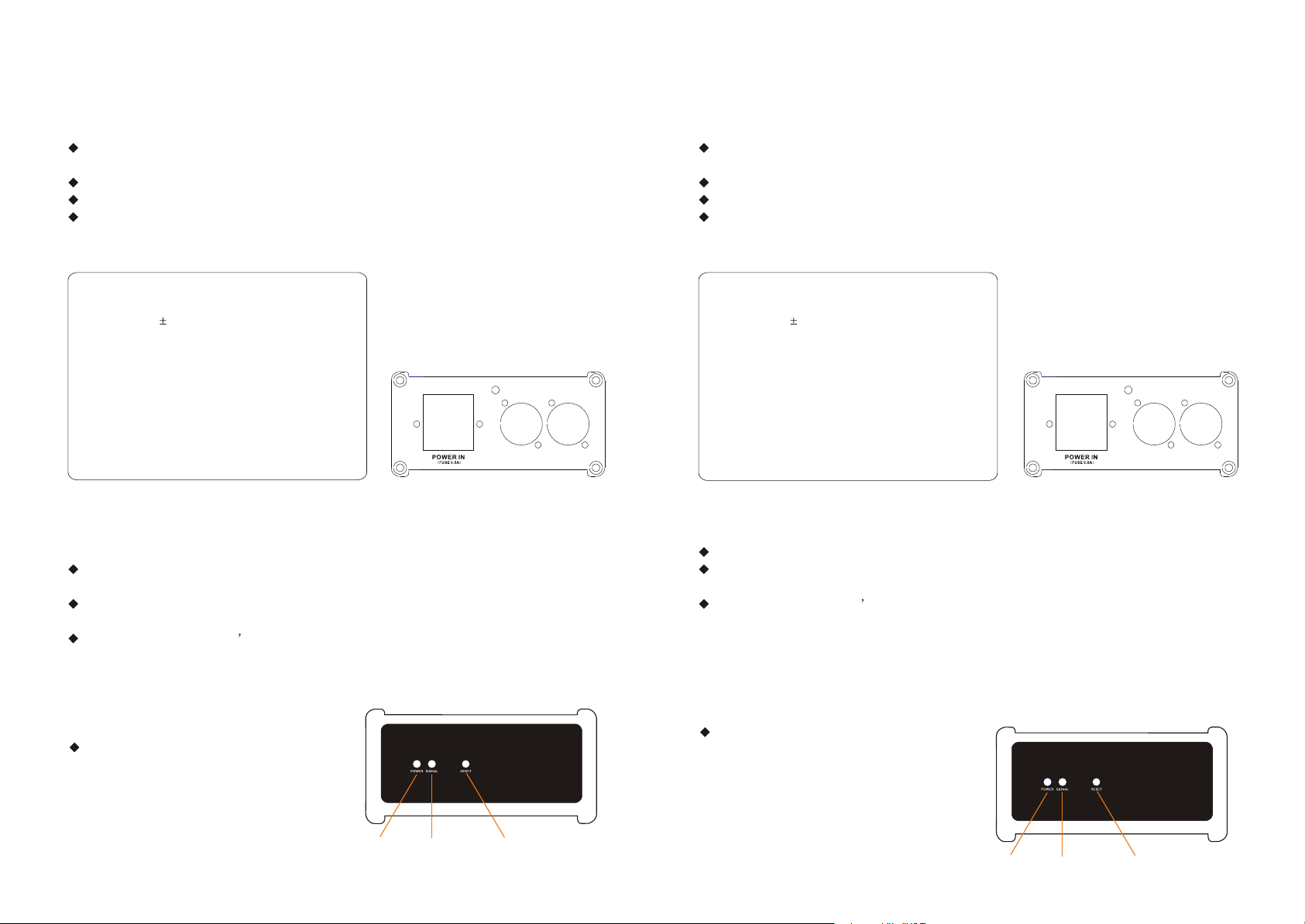
2.1 Transmitter
1 Attach the antenna to the connector on the front panel. If using the standard antenna, use also
the supplied adaptor.
2 Link the DMX source to the DMX in socket on the rear panel.
3 Connect power to the unit via the AC power input (90 to 250VAC).
4 If required, attach the supplied trussholder brackets to the top cover of the unit .
DMX Interface
Transceivers on bus: 32 (max)
Data rate: 250 kbps (max)
ESD protection*: 15 kV
AC input
90-250VAC 50/60Hz
1A at 115VAC (max)
0.5A at 230VAC (max)
Compliance declarations
ETSI: EN300 328 & 300 826
EMC: EN301 489-17
CE: EN60950
FCC: UQT-WDXOEMPCBF
IC: 6812A-WDMXOEM
ARIB: 06215559/AA/00
RF characteristics
Output power:
20 25** dBm
100 300** mW
Frequency range:
2402 to 2479 MHz
Channel bandwidth: 1
Sensitivity at 0.1%
BER: -95dBm
* Slewrate limited for
minimum of EMI in
unterminated networks.
** Only in FCC output
power mode.
TRANSMITTER INTERFACE
DMX IN
DMX OUT
2.1.1 To add receivers
Note: You can add receivers at any time, even during operation.
1 Power on the receiver unit(s) and ensure that they are not linked with any other transmitter
(LINK indicators should be OFF).
2 On the transmitter unit, press and release the FUNCTION button. The transmitter will scan for
all unlinked receivers for a period of ten seconds - the LINK indicator will flash rapidly.
3 If successful, each receiver s LINK indicator will go ON. If any failed, check that the receiver is
in range and repeat procedure.
2.2 Receiver
1 Attach the antenna to the connector on the front panel. If using the standard antenna, use also
the supplied adaptor.
2 Link the DMX source to the DMX in socket on the rear panel.
3 Connect power to the unit either via the AC power input (90 to 250VAC).
4 If required, attach the supplied trussholder brackets to the top cover of the unit .
DMX Interface
Transceivers on bus: 32 (max)
Data rate: 250 kbps (max)
ESD protection*: 15 kV
AC input
90-250VAC 50/60Hz
1A at 115VAC (max)
0.5A at 230VAC (max)
Compliance declarations
ETSI: EN300 328 & 300 826
EMC: EN301 489-17
CE: EN60950
FCC: UQT-WDXOEMPCBF
IC: 6812A-WDMXOEM
ARIB: 06215559/AA/00
RF characteristics
Output power:
20 25** dBm
100 300** mW
Frequency range:
2402 to 2479 MHz
Channel bandwidth: 1
Sensitivity at 0.1%
BER: -95dBm
* Slewrate limited for
minimum of EMI in
unterminated networks.
** Only in FCC output
power mode.
RECEIVER INTERFACE
DMX IN
DMX OUT
2.2.1 To link with a transmitter
1 Ensure that this receiver is not linked with any other transmitter (LINK indicator should be OFF).
2 On the transmitter unit, press and release the FUNCTION button. The transmitter will scan for
all unlinked receivers for a period of ten seconds.
3 If successful, the receiver s LINK indicator will go ON. One or more Level indicators will then
show the signal strength.
2.1.2 To unlink all receivers
1 On the transmitter, press and hold the
FUNCTION button until LINK begins flashing.
All registered receivers will be unlinked.
2.2.2 To unlink from a transmitter
1 On the receiver, press and hold the FUNCTION
W-DMX TX
Power LED
Signal LED
Reset
2
button until the LINK indicator goes OFF. The
receiver is now unlinked.
3
Power LED
Signal LED
W-DMX RX
Reset
 Loading...