

Page 1
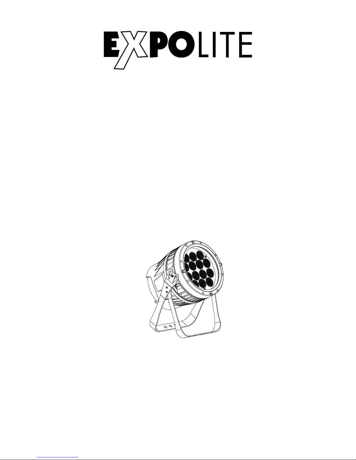
Tour-LED Power 56 Zoom
Art.Nr.: led28385
Bedienungsanleitung
Bedienungsanleitung bitte aufbewahren
Keep this Manual for later queries
Änderungen sind ohne Ankündigung möglich.
Changes are possible without prior notice.
Rev. 2018-01-08
User Manual
Eigenschaften
Menüführung
DMX-Steuerung
Specifications
Menu
DMX-Control
MK II
Page 2

FOCON SHOWTECHNIC
Vertriebsgesellschaft mbH
Teichweg 4+6
D-49504 Lotte/Wersen
Telefon: ++49 (0) 541-77095-0
Fax: ++49 (0) 541-77095-27
[email protected]
www.focon-showtechnic.com
by
Die beiliegenden Bedienhinweise für Expolite
Geräte sind Bestandteil dieser Bedienungsanleitung. Lesen Sie diese sorgfältig, bevor
Sie das Gerät in Betrieb nehmen.
The enclosed General Informations for Expolite
Units are part of these user manual. Read them
carefully before operating the device.
Page 3
Inhalt - Content
Inhalt - Content
Seite / Page
Lieferumfang
Technische Daten
Abmessungen
Installation
Bedienung
Steuerung mit DMX512
Delivery
Product Information
Dimensions
Installation
Operation
Using DMX512 Controler
DE
D-04
D-05
D-06
D-07
D-08
D-13
E-20
E-21
E-22
E-23
E-24
E-29
ENG
Page 4

Lieferumfang
- Expolite TourLED Power 56 Zoom MKII
Expolite Geräte werden vor dem Versand sorgfältig geprüft. Sollte der
Lieferumfang dennoch nicht vollständig sein, wenden Sie sich an bitte umgehend
an Ihren Vertriebspartner.
- Zubehörset Displayabdeckung
- Anschlusskabel für Spannungsversorgung
- Bedienhinweise für Expolite Geräte
- Bedienungsanleitung
D-04
Page 5
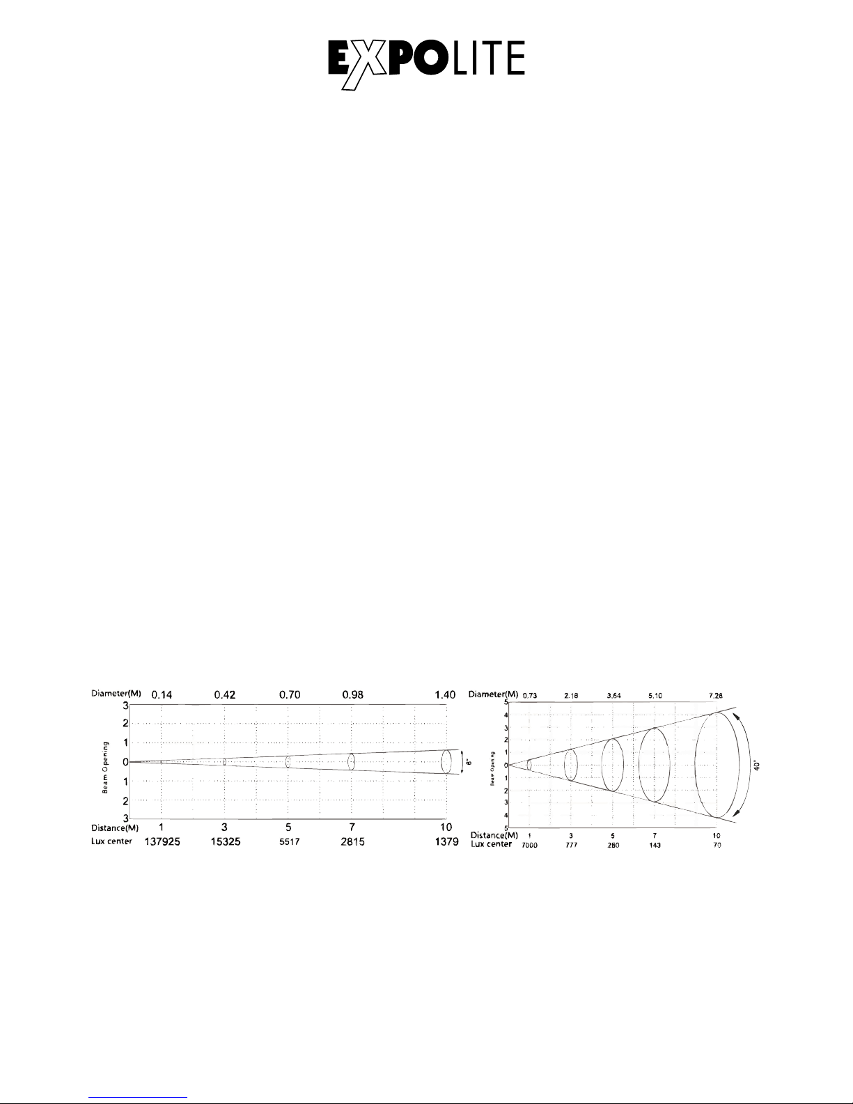
Technische Daten
Spannungsversorgung
Maximale Leistungsaufnahme
Gewicht
Betriebstemperatur
Abmessungen
Luftfeuchtigkeit*
Schutzklasse
Gehäuse
LED´s
LED Treiberstrom
Abstrahlwinkel
Steuerung
DMX-Kanäle
Anschlüsse
100V - 240V AC 50/60Hz
235W
330 x 283 x 236 mm
8.6 kg
Power In/Out | DMX In/Out
-20°C - 45°C
< 80%
Ip65
Alu-Guss, schwarz Pulverbeschichtet
14 x 12W 4in1 RGBW
700mA
8° - 40°
Stand-Alone / Master-Slave / DMX512
3 - 17 (3/3/4/4/5/6/7/12/17)
* Siehe Allgemeine Bedienhinweise für Expolite Geräte - Hinweise zu Kondenswasserbildung im Geräteinneren
D-05
Page 6
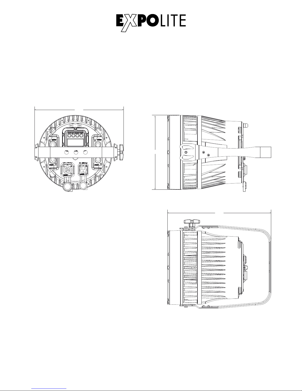
Abmessungen
D-06
283
236
330
Page 7
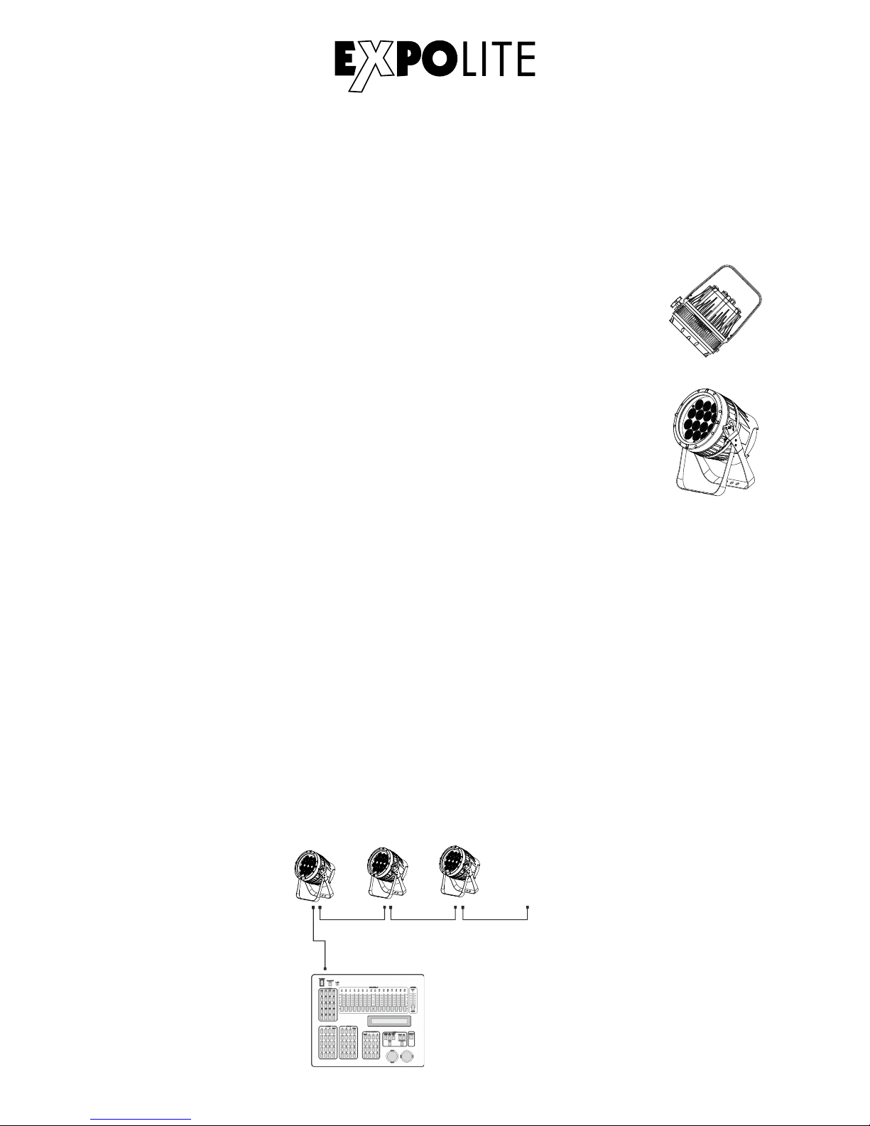
Installation
Montage
Hängend
Das Gerät kann in jeder beliebigen Position verwendet werden. An dem
Montagebügel sind Bohrungen vorhanden, durch die gängige Halterungen
sicher montiert werden können. Geräte müssen entsprechend der jeweils
gültigen Vorschriften sicher montiert und mit einer zweiten Sicherung gegen
herabfallen versehen werden. Hierzu ist am Gerät eine Öse für Safeties
angebracht.
Stehend
Das Gerät kann direkt auf den montierten Bügel gestellt werden. Hierzu muss
dieser bis in den mechanischen Anschlag aufgeklappt werden.
HINWEIS
Das LED Modul kann in jeder beliebigen Lage betrieben werden. Um das
Gerät in seiner Montageposition aus zu richten, müssen die Knebelschrauben
gelöst werdn.
Verbindung der Spannungsversorgung
Bei 230V Netzspannung: maximal 10 Geräte in Reihe
Bei 120V Netzspannung: maximal 5 Geräte in Reihe
DMX 512
CON TROLL ER
............
DM X Add r.1 DM X Add r.( Nx1)+1 DM X Add r.( Nx2)+1
DMX-Verbindung
Die Geräte mit geeigneten DMX-Kabel miteinander und mit dem Kontroller verbinden
Die vorgesehen DMX-Adressen und Personalities an den Geräten einstellen
D-07
Page 8
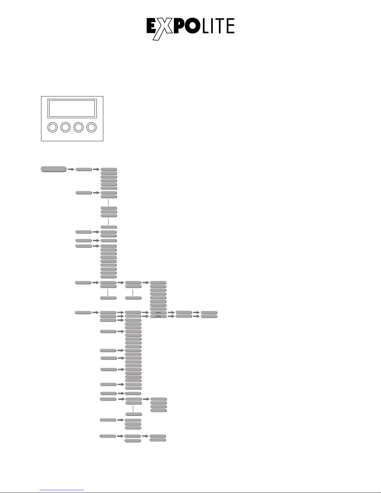
Bedienung
Menüstruktur
MENU - Taste:
ENTER-Taste:
UP-Taste:
DOWN-Taste
ENT ER UP
DOW N
MEN U
Eine Menüebene aufwärts
In gewähltes Menü springen; Eingabe bestätigen
Aufwärts blättern; Wert erhöhen
Abwärts blättern; Wert verringern
Bedienelemente am Gerät
D-08
RUN DMX
SLAV
AT. 01
AT.02
AT.10
AUTO
PR.C1
PR.C2
PR.10
D.(001~512)
DMX
TOUR
ARC .1
ARC.2
AR1.D
AR2.S
AR2.D
ME NU
R.( 0~255 )
G.(0~255)
B.(0~255)
W.(0~255)
S.(0~20)
STAT
PER S
HSV
PR.C1
PR.C2
PR.10
SC.01
SC.02
SC.30
EDIT
R.(0~255)
G.(0~255)
B.(0~255)
W.(0~255)
T.(0~255)
F.(0~255)
Z.( 0~255 )
T.( 0~255 )
T.(0~255)
S.(0~20)
Z.(0~255)
TR1 6
AR2.Z
SET
UPLD
REST
OFF
COLR
DIM 3
DIM1
DIM2
DIM4
DIM
RGBW
UC
OF F
PAS S
PASS
SEND
END
REST
END
KEY ON
OFF
CAL
RGBW
BLAC
SAVE
DERR
POS2
POS1
ZOOM
** **
WH. 01
WH.02
WH.11
R.( 0~255 )
G.(0~255)
B.(0~255)
W.(0~255)
WT
R.( 0~255 )
G.(0~255)
B.(0~255)
ZOO M
POS .1
POS.2
P(0 ~255)
P(0~255)
BAS E
CV3
CV2
CURV
CV1
OFF
Page 9
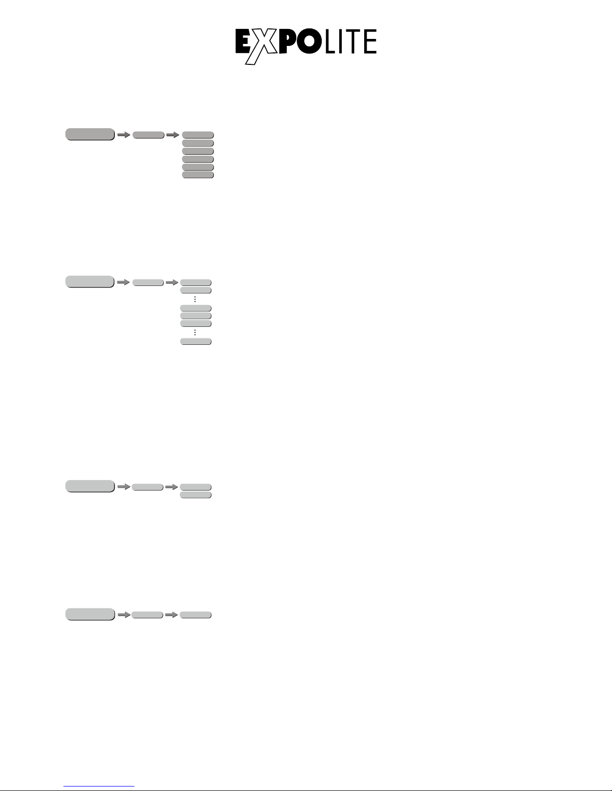
Statische Farbe einstellen
Im Menü werden im Punkt „STAT“ statische Farben für den Stand-Alone Betrieb
eingestellt. Diese werden anhand der DMX-Werteskala 0-255 für Rot, Grün, Blau und
Weiß, Zoom sowie dem Stroboskopwert 0-20Hz gemischt.
MENU
AT.01
AT.02
AT.10
AUT O
PR. 01
PR. 02
PR. 10
Automatikprogramme abspielen
Im Menü werden im Punkt „AUTO“ die im Gerät gespeicherten Automatikprogramme abgespielt.
Die Programme „AT01" bis „AT10" sind fest im Gerät hinterlegt. Die Programme „PR01" bis
„PR10" sind editierbar. Dies wird unter „Editieren von Benutzerprogrammen“ beschrieben.
Automatikprogramme werden als Master an verbundene Slave-Geräte übertragen. Für den
Master-Slave Betrieb werden Signale über die DMX-Leitung gesendet. Dies kann dritte Geräte
stören.
Betriebsmodus DMX / Slave
MENU
RUN DMX
SLAV
Im Menü wird im Punkt „RUN“ der Betriebsmodus eingestellt. Für den Betrieb an einem DMXKontroller muss „DMX“ aktiviert werden. Für den Betrieb als Slave-Gerät muss „SLAV“ aktiviert
werden. Im Slave-Modus empfängt das Gerät statische Farben oder abgespielte Automatikprogramme von einem verbundenen Master-Gerät.
MENU
D.( 001~5 12)
DMX
DMX-Adresse einstellen
Im Menü wird im Punkt „DMX“ die DMX-Startadresse des Gerätes eingestellt. Diese bleibt auch
bei dem Wechsel der Personality erhalten.
D-09
R.( 0~255 )
G.(0~255)
B.(0~255)
W.(0~255)
S.(0~20)
MENU
STAT
Z.( 0~255 )
Page 10
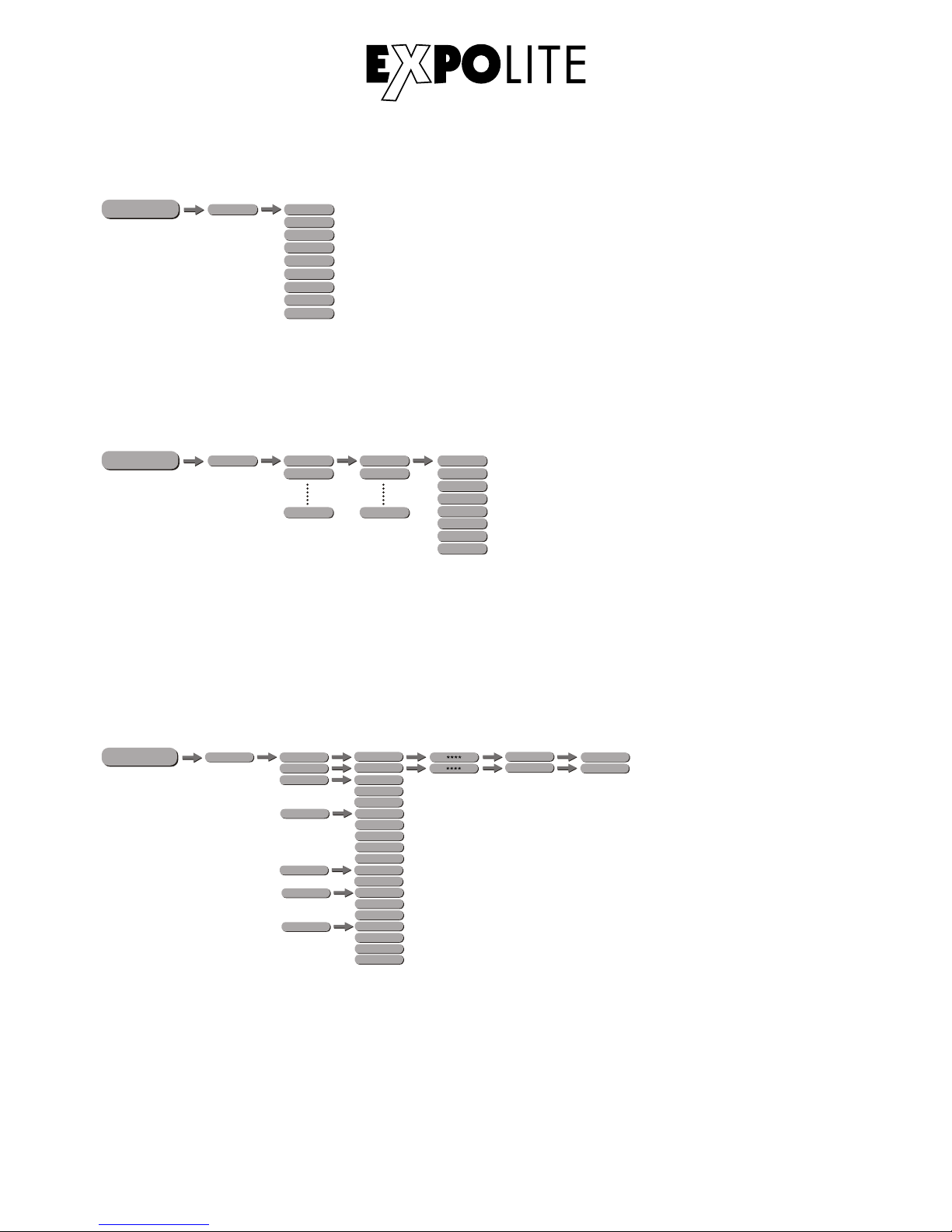
Personality einstellen
Im Menü wird im Punkt „PERS“ die gewünschte DMX-Personality eingestellt. Die Kanalbelegung
der einzelnen Personalities ist im Kap. „Steuerung über DMX512" ersichtlich.
Benutzerprogramme editieren
Im Menü wird im Punkt „EDIT“ werden die Benutzerprogramme „PR01" bis „PR10" editiert.
Jedes Programm kann aus bis zu 30 Schritten bestehen. Jeder Schritt besteht aus den
Parametern Farbe „RGBW“, Zoom, Strobe „0-20Hz“, Dauer des Steps „Time“ und Überblendzeit
„Fade“. Benutzerprogramme können auf andere Geräte überspielt werden, siehe Erweiterte
Einstellungen.
Erweiterte Einstellungen
Im Menü „SET“ werden erweiterte Geräteeinstellungen vorgenommen. Das Passwort für
für Einstellungen ist „UP“-“DOWN“-“UP“-“DOWN“-“ENTER“ und kann nicht geändert werden.
„UPLD“: Die Uploadfunktion überträgt Benutzerprogramme auf verbundene Slave-Geräte. Diese
müssen hierzu im Betriebsmodus „RUN“ auf Slave gestellt werden.
„REST“: Reset führt einen vollständigen Gerätereset durch und stellt die Werkseinstellungen her
D-10
TOUR
ARC .1
ARC.2
AR1.D
AR2.S
AR2.D
PERS
HSV
MENU
TR1 6
AR2.Z
R.( 0~255 )
G.(0~255)
B.(0~255)
W.(0~255)
Z.(0~255)
T.(0~255)
F.(0~255)
PR.C1
PR.C2
PR.10
SC.01
SC.02
SC.30
EDIT
MENU
S.( 0~20)
MENU
SET
UPLD
REST
OFF
COLR
DIM 3
DIM1
DIM2
DIM4
DIM
RGBW
UC
OF F
PAS S
PASS
SEND
END
REST
END
BLAC
SAVE
DERR
POS2
POS1
ZOOM
BASE
CV3
CV2
CURV
CV1
OFF
Page 11
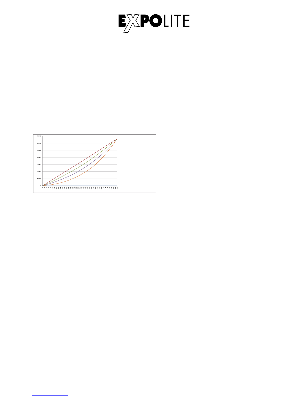
„COLR“: Im Menü Color wird die Farbkalibrierung gewählt oder deaktiviert. Wenn „RGBW“
gewählt wird, werden die maximalen Helligkeitswerte bei DMX=255 auf die in „CAL2"
hinterlegten Werte begrenzt. Wenn „UC“ für Uniform-Color gewählt wird, wird die Werkseitige
Kalibrierung benutzt, die Geräte unterschiedlicher Generationen angleicht. Wird der Wert „OFF“
geschaltet, ist die Kalibrierung deaktiviert und das Gerät erreicht die maximale Helligkeit.
„DIM“: Dim4 Technologie zur Halogensimulation. Im Menüpunkt „DIM“ wird die Dimmer
Geschwindigkeit eingestellt. Diese Abklingkurven simulieren das abblenden klassischer Halogen
Leuchtmittel. Bei „OFF“ reagiert das Gerät direkt.
„CURV“: Im Menüpunkt Curve wird die Dimmerkurve wie auf der Abbildung ersichtlich eingestellt.
CURV dimming
1: OFF
2: Cv1
3: CV3
4: Cv4
1
2
3
4
(100 %)
„DERR“: Im Menüpunkt DMX-Error wird eingestellt, ob das Gerät im Fall einer Signalunterbrechung den letzten bekannten Wert hält „SAVE“ oder abblendet „BLAK“.
„ZOOM“: Im Menüpunkt Zoom werden die beiden Anschläge des Zoombereichs kalibriert. Die
Position „BASE“ ist die Deafult-Position, auf die der Zoom nach einem Neustart fährt.
D-11
Page 12

Kalibrierung und Weißabgleich
Im Menüpunkt „WH.xx werden die abrufbaren Farbtemperaturen für die Weißwerte
hinterlegt. Diese werden aus den Parametern „RGBW“ gemischt.
Im Menüpunkt „RGBW“ wird eine Benutzerdefinierte Farbkalibrierung gespeichert.
Diese begrenzt die maximale Helligkeit der Farbkanäle bei dem DMX-Wert „255".
HINWEIS: Der Maximalwert kann auf „0" begrenzt werden. In diesem Fall reagiert ein Farbkanal
nicht auf einen gesendeten DMX-Wert. Dies kann als Gerätefehler Fehlinterpretiert werden.
Im Menüpunkt „CAL“ werden alle Kalibrierungen auf Werkseinstellungen zurück gesetzt.
Zoom-Range
Im Menüpunkt „ZOOM“ wird der Zoombereich für die Steuerung über DMX begrenzt. Die in hier
eingestellten Werte sind der kleinste und größte über DMX anfahrbare Bereich.
D-12
MENU
WH. 01
R. (0~255 )
WH. 02
G. (0~255 )
B.( 0~25 5)
W.(0~ 255)
WH. 11
RGB W
R. (0~2 55)
G.(0~255)
B.(0~255)
** **
CAL
MENU
ZOO M
POS.1
P( 0~25 5)
POS .2
P( 0~25 5)
Page 13
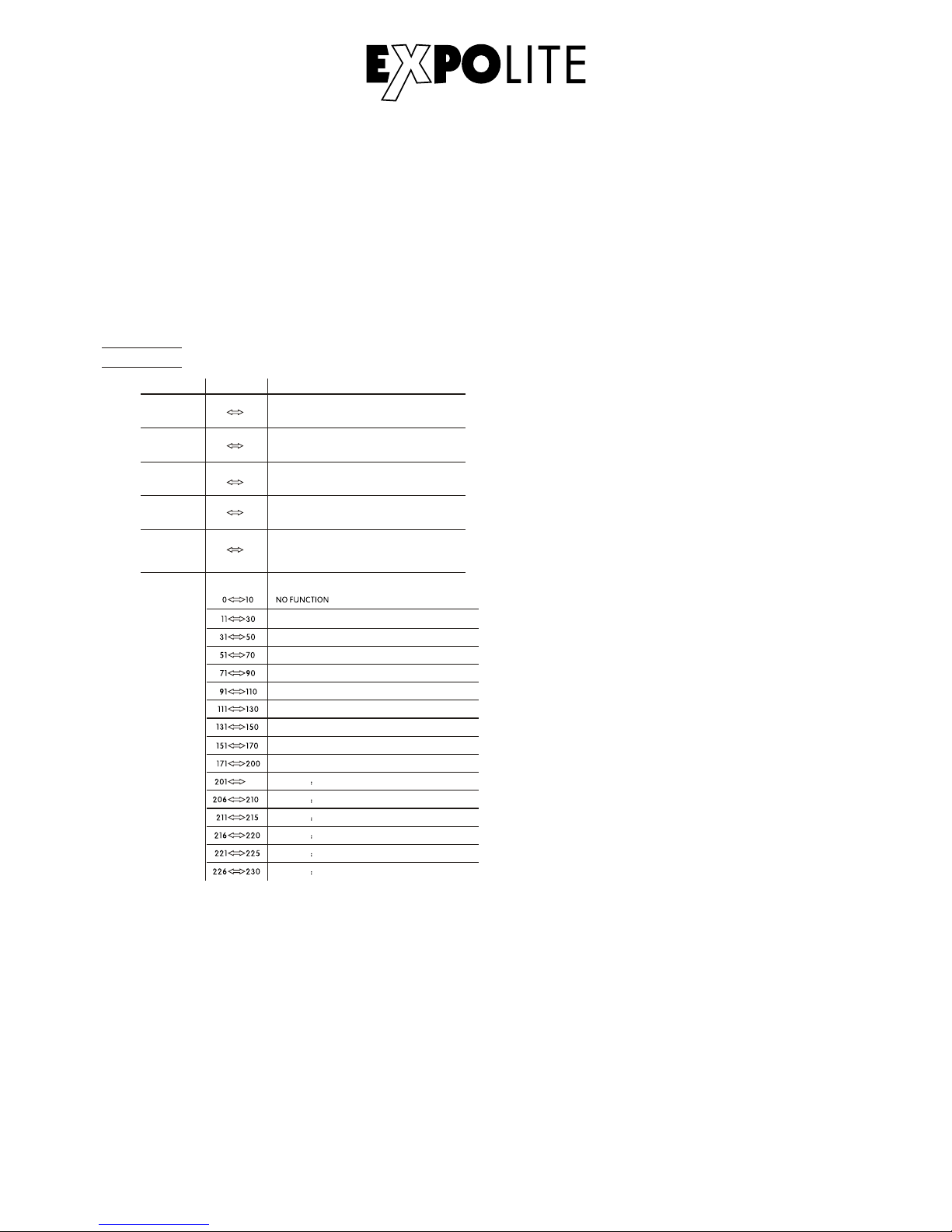
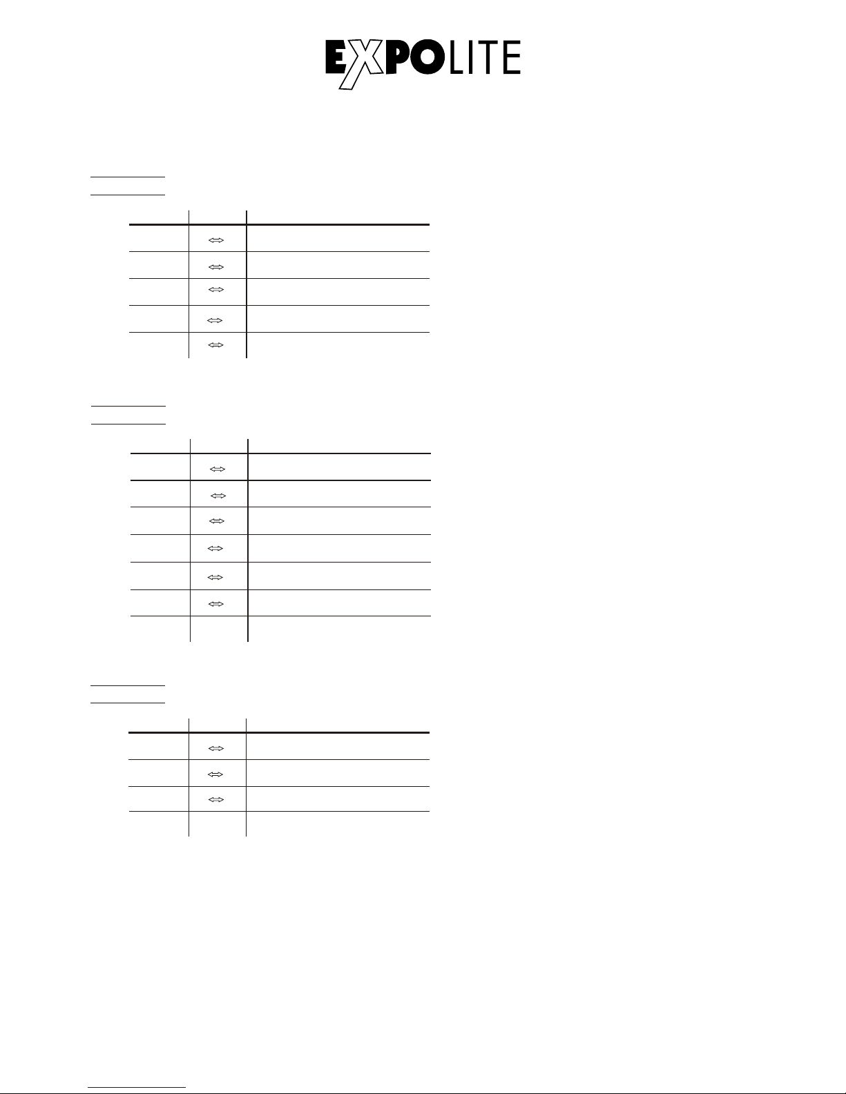
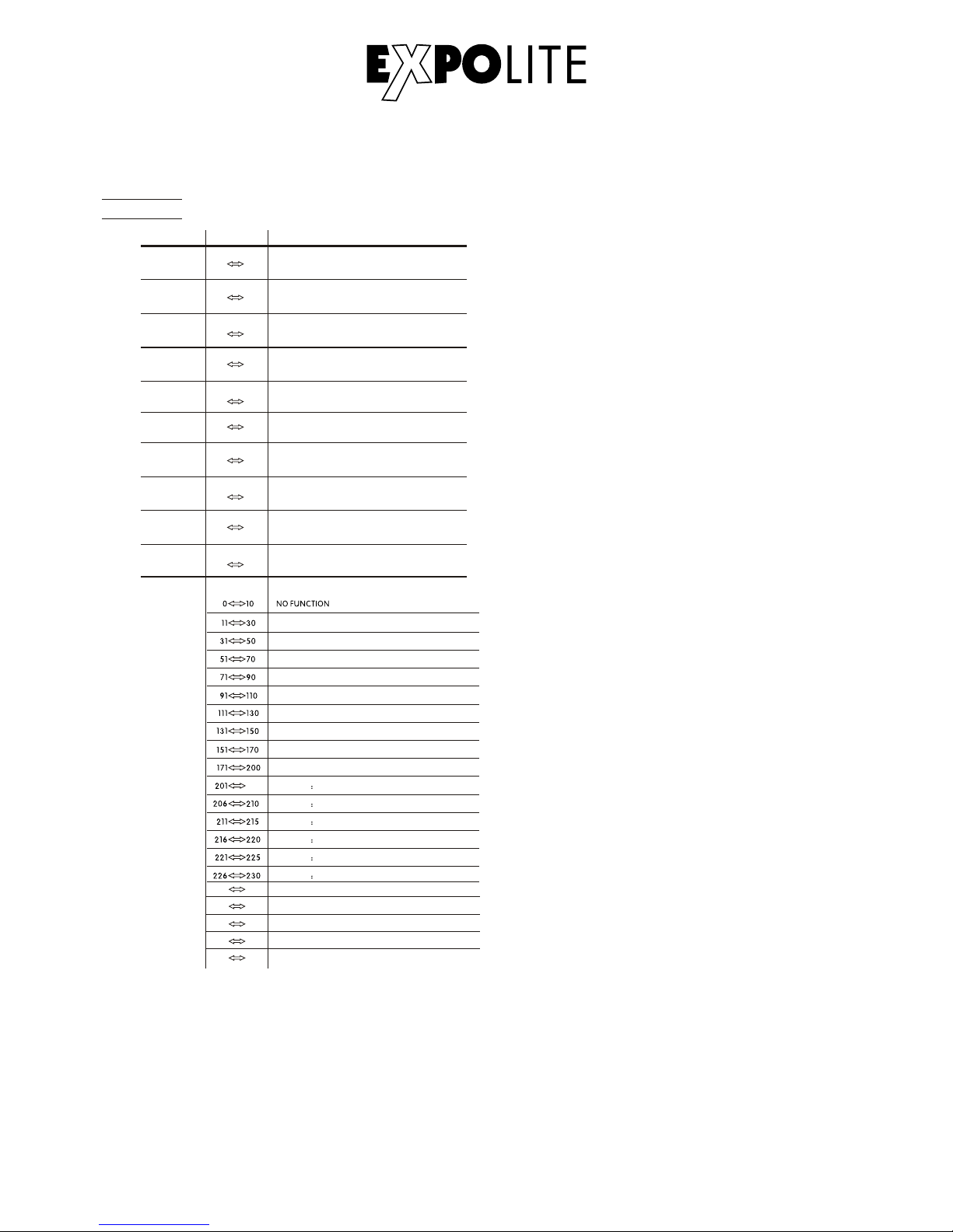
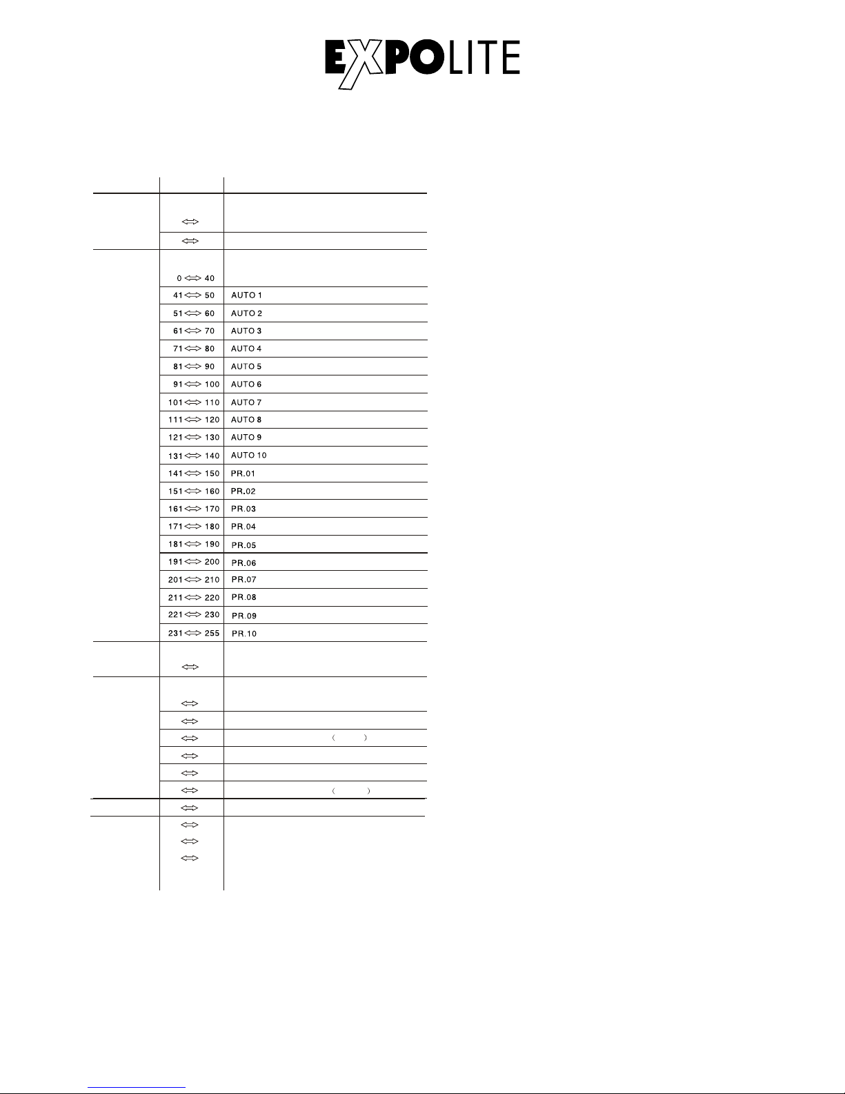
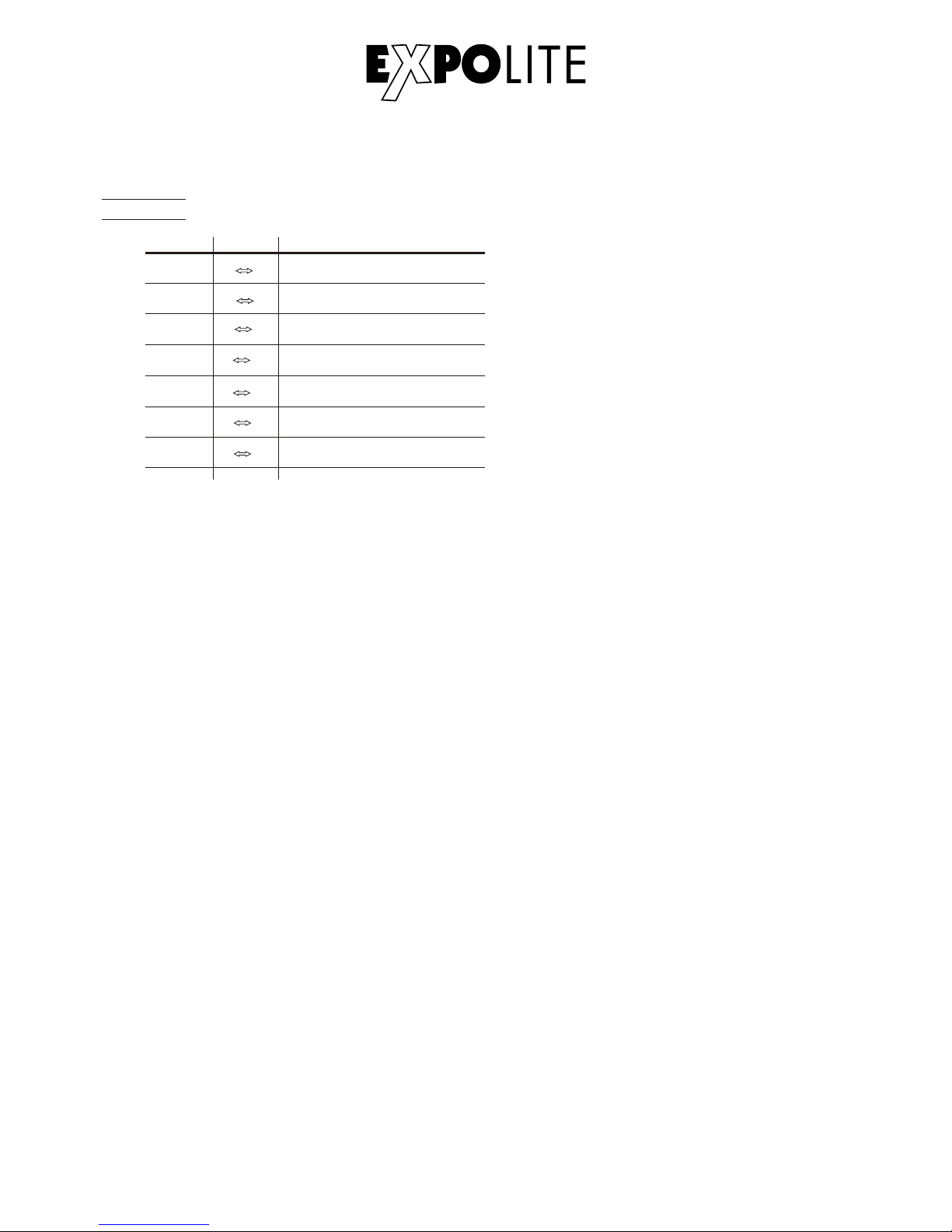
DMX-Kanalbelegung
Dieses Gerät verfügt über verschiedene DMX-Personalities. Bei diesen werden unterschiedlich
viele DMX-Kanäle belegt und die Reaktion des Gerätes unterscheidet sich entsprechend.
Es sind 9 DMX-Personalities mit 3, 3, 4, 4, 5, 6, 7, 12 und 17 Kanälen wählbar.
Steuerung mit DMX512
D-13
TOUR
1
2
0 255
3
4
0 255
0 255
0 255
5
0 255
CHAN NE L FUNCTIONVALUE
BLU E
WHITE
GREEN
(or FADE TIME when CUS.01-CUS.10 in CH8 is activated)
RED
(or STEP TIME when CUS.01-CUS.10 in CH8 is activated)
MASTER DIMMER
6
WHI TE1 320 0K
WHITE2 3400K
WHITE3 4200K
WHITE4 4900K
WHITE5 5600K
WHITE6 5900K
205
RED 100%/ GREEN 1 00%P/ BLUE1 00%/W HITE 10 0%
RED 0%/GREEN DOWN/BLUE 100%
RED UP/GREEN 0%/BLUE100%
RED100%/GREEN 0%/BLU EDOWN
RED100%/GREEN UP/BLUE UP
RED DOWN/GREEN DOWN/BLUE 100%
RED100%/GREEN UP/BLUE0%
RED DOWN/GREEN 100%/BLUE0%
RED 0%/GREEN 100%/BLUE UP
COL OR MACR O
Page 14
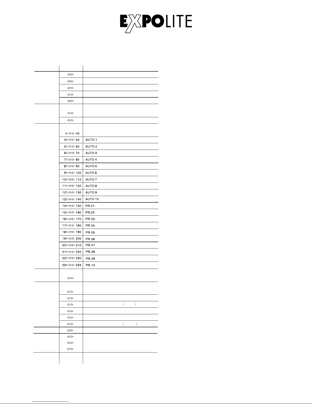
D-14
11
0 255
12
000 200
201 220
221 255
CHAN NEL FUNCTIONVALUE
7
8
0 10
1~20Hz
11
255
0 255
9
231 235
236 240
241 245
246 250
251 255
WHITE 7: 6500K
WHITE 8: 7200K
WHITE 9: 8000K
WHITE 10: 8500K
WHITE 11: 10000K
6
DIMMER SPEED
LINEAR DIMMER
NON LINEAR DIMMER 1 fastest
10 29
30 69
70 129
130 189
190 255
10
NON L INEAR D IMMER 2
NON LINEAR DIMMER 3
NON LINEAR DIMMER 4 slowest
NO FUNCTION
AUTO
NO FUNCTION
STROBE
AUTO SPEED ADJUSTMENT
When using CH 8,AU TO01-AUTO 10, th is function a ctiv ated
0 9
PRESE T DI MM ER S PEED FR OM D IS PLA Y ME NU
ZOO M
NO FUNCTION
ZOOM RESET
NO FUNCTION
Page 15
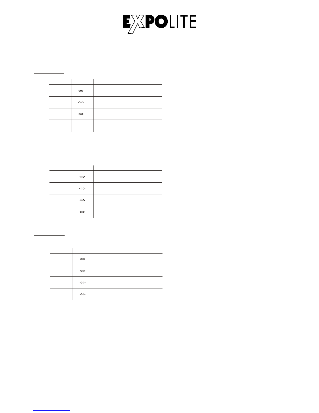
D-15
AR C .1
BLU E
1
2
0 25 5
CHAN NE L FUNCTIONVALUE
3
0 25 5
0 25 5
GREEN
RED
AR 1 .D
BLU E
1
2
0 25 5
CHAN NE L FUNCTIONVALUE
3
4
0 25 5
0 25 5
0 25 5
GRE EN
RED
MASTER DIMMER
AR C .2
BLU E
1
2
0 25 5
CHAN NE L FUNCTIONVALUE
3
4
0 25 5
0 25 5
0 25 5
GRE EN
RED
WHITE
Page 16
D-16
BLU E
3
4
0 2 55
0 2 55
GRE EN
WHITE
5
0 2 55
AR 2 .D
1
2
0 2 55
CHAN NE L FUNCTIONVALUE
0 2 55
RED
MASTER DIMMER
AR 2 .S
1
2
0 2 55
CHAN NE L FUNCTIONVALUE
3
0 2 55
0 2 55
HS V
1
2
0 2 55
CHAN NE L FUNCTIONVALUE
3
0 2 55
0 2 55
VALUE(0~100%)
SATURATION(0~100%)
HUE(0~100%)
4
5
6
0
0
0
255
255
255
BLUE
GREEN
RED
WHITE
MASTER DIMMER
STROBE
Page 17
D-17
TR16
1
2
0 255
3
4
0 255
0 255
0 255
5
0 255
CHAN NE L FUNCTIONVALUE
MAS TER DIM MER
11
WHI TE1 320 0K
WHITE2 3400K
WHITE3 4200K
WHITE4 4900K
WHITE5 5600K
WHITE6 5900K
205
RED 100%/ GREEN 1 00%P/ BLUE1 00%/W HITE 10 0%
RED 0%/GREEN DOWN/BLUE 100%
RED UP/GREEN 0%/BLUE100%
RED100%/GREEN 0%/BLU EDOWN
RED100%/GREEN UP/BLUE UP
RED DOWN/GREEN DOWN/BLUE 100%
RED100%/GREEN UP/BLUE0%
RED DOWN/GREEN 100%/BLUE0%
RED 0%/GREEN 100%/BLUE UP
COL OR MACR O
6
7
0 255
8
9
0 255
0 255
0 255
10
0 255
GREEN
WHITE FINE
MASTER DIMMER FINE
RED
RED FINE
GREEN FINE
BLUE
BLUE FINE
WHITE
231 235
236 240
241 245
246 250
251 255
WHITE 7: 6500K
WHITE 8: 7200K
WHITE 9: 8000K
WHITE 10: 8500K
WHITE 11: 10000K
Page 18
D-18
16
0 255
17
000 200
201 220
221 255
CHAN NEL FUNCTIONVALUE
12
13
0 10
1~20Hz
11
255
0 255
14
DIM MER SPE ED
LINEAR DIMMER
NON LINEAR DIMMER 1 fastest
10 29
30 69
70 129
130 189
190 255
15
NON L INEAR D IMMER 2
NON LINEAR DIMMER 3
NON LINEAR DIMMER 4 slowest
NO FUNCTION
STROBE
AUTO SPEED ADJUSTMENT
When using CH 13,A UTO01 -AUT O10, this fun ctio n activated
0 9
PRE SET DIM MER SPEED F RO M DISPL AY M EN U
ZOO M
NO FUNCTION
ZOOM RESET
NO FUNCTION
NO FU NC TI ON
AUTO
Page 19
D-19
AR 2 .Z
1
2
0 2 55
CHAN NE L FUNCTIONVALUE
3
0 2 55
0 2 55
4
5
6
0
0
0
255
255
255
BLUE
GREEN
RED
WHITE
MASTER DIMMER
ZOOM
7
0 2 55
ZOOM RESET
Page 20

Delivery
- Expolite TourLED Power 56 Zoom MKII
Expolite devices are carefully checked before shipment. If the delivery is not
complete, please contact your distributor immediately.
- Acessoiry Set for Displaycover
- Powercable
- General Informations for Expolite Units
- User Manual
E-20
Page 21
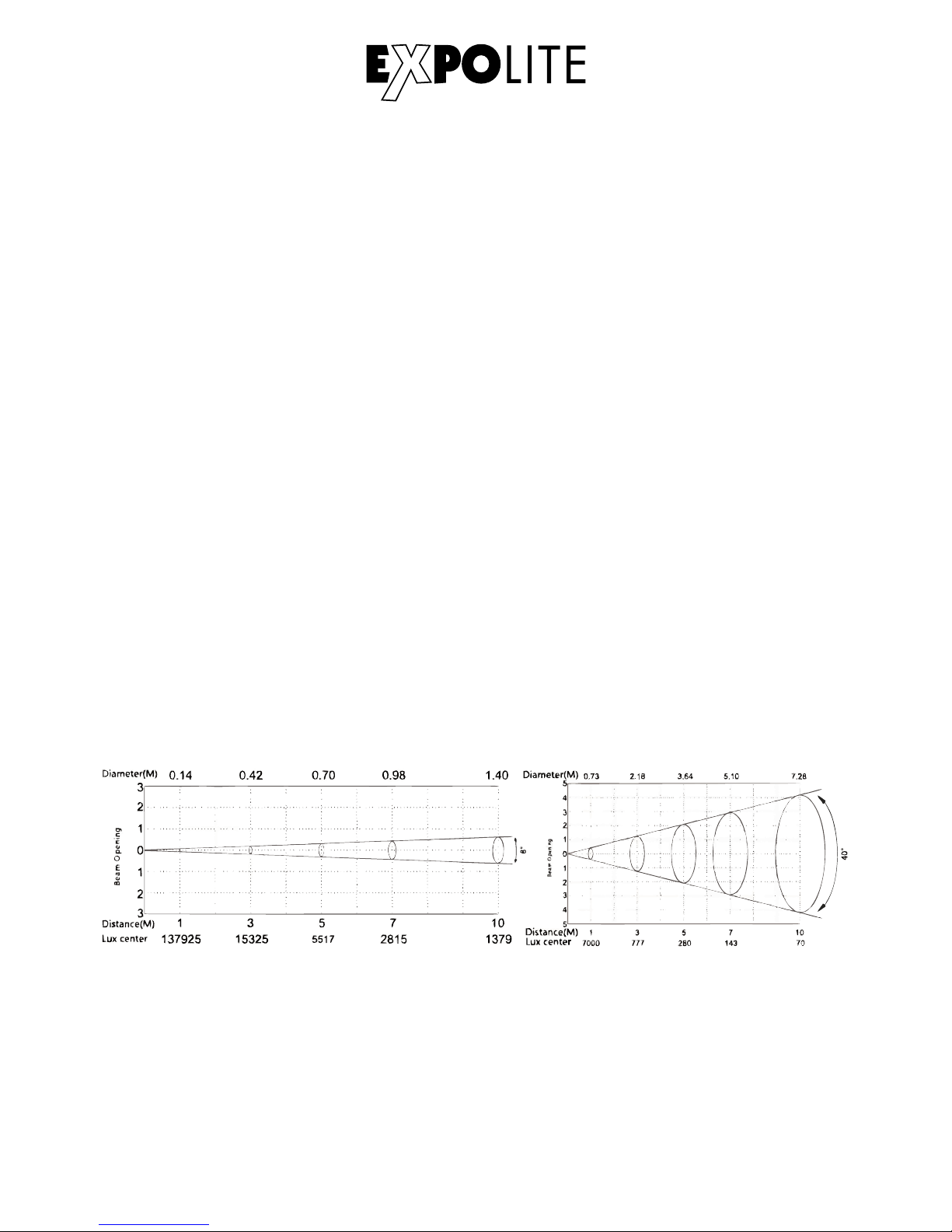
Product Information
Voltage
Power Consumption
Weight
Ambient Temperature
Dimensions
Humidity*
Protection
Housing
LED´s
LED Current
Optic´s
Control
DMX-Channels
Connectors
* take note too General Informations for Expolite Units - Notes for Condensation inside Housing
E-21
100V - 240V AC 50/60Hz
235W
330 x 283 x 236 mm
8.6 kg
Power In/Out | DMX In/Out
-20°C - 45°C
< 80%
Ip65
Die-Cast Aluminium, Black Coated
14 x 12W 4in1 RGBW
700mA
8° - 40°
Stand-Alone / Master-Slave / DMX512
3 - 17 (3/3/4/4/5/6/7/12/17)
Page 22
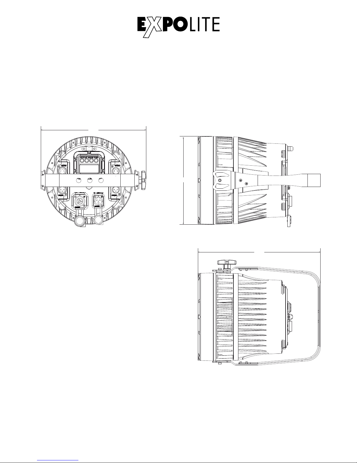
Dimensions
E-22
283
236
330
Page 23
Installation
Mounting
Hanging
The device can be used in any position. On the mounting bracket are holes
available, for attaching standard brackets. Units must be safe mounted in
accordance with the relevant regulations and provided with a safetycord to
prevent falling. For this purpose, an eyelet for Safeties is attached to the device.
Standing
The device can be placed directly on the mounted bracket. For this purpose,
it must be opened up to the mechanical stop.
NOTE
The LED module can be operated in any position. To bring the device in its
mounting position, the toggle screws must be loosened.
Powerconnection
230V: max. 10 Units
120V: max 5 Units
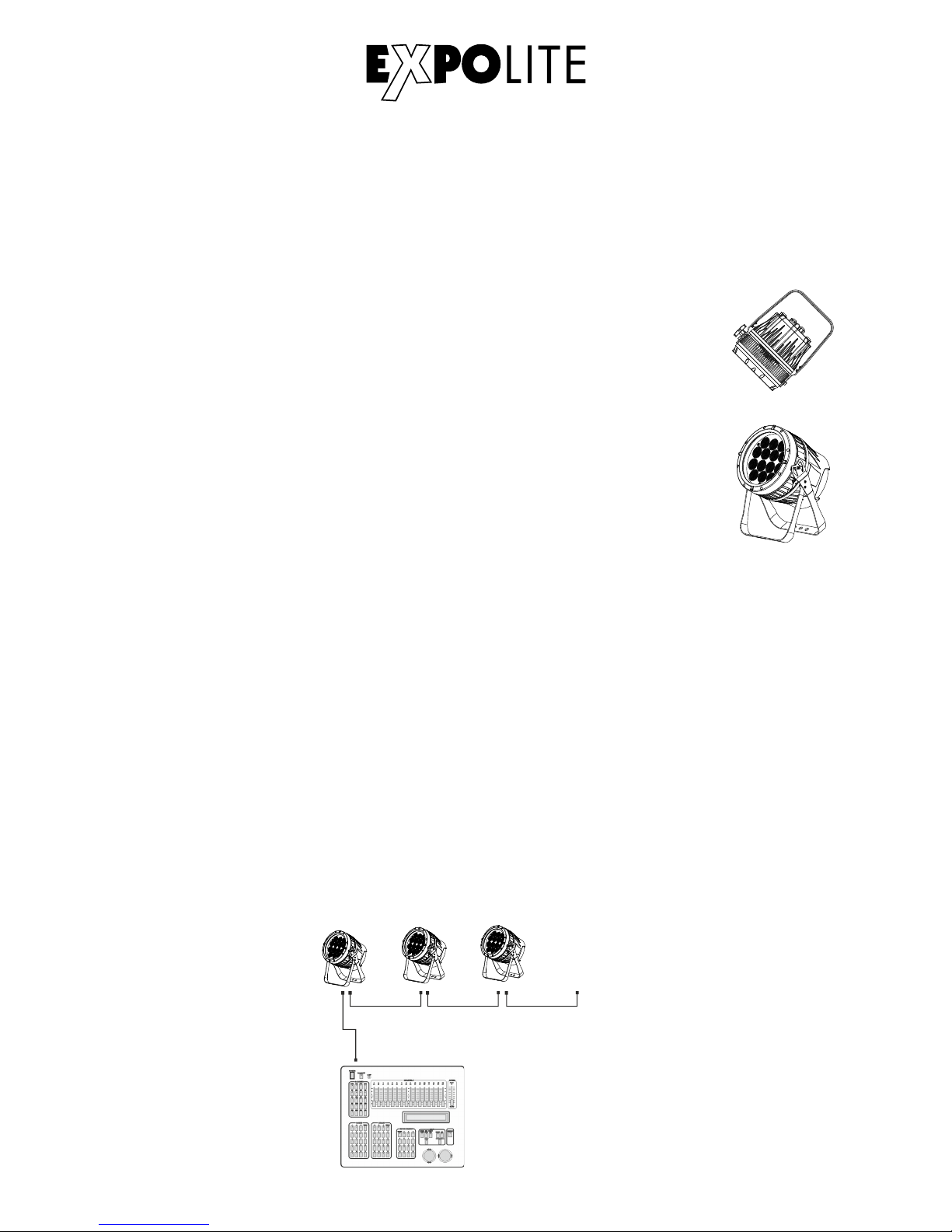
DMX 512
CON TROLL ER
............
DM X Add r.1 DM X Add r.( Nx1)+1 DM X Add r.( Nx2)+1
DMX-Connection
Use specified DMX-Cable to connect the Units to each other and to connect them to the controldesk. Enter the adresses and personality to the units.
E-23
Page 24
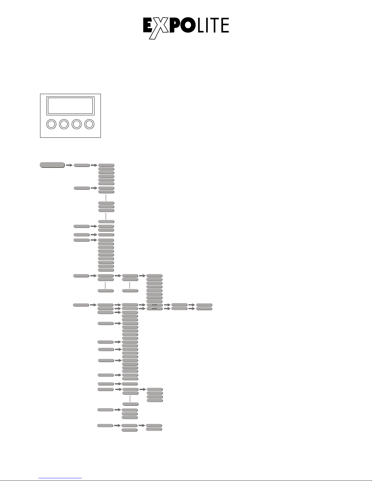
Operation
Menu Map
MENU:
ENTER:
UP:
DOWN:
ENT ER UP
DOW N
MEN U
Return to previous menu
Enter currently selected menu
Scroll Up, Increase value
Scroll down: Decrease value
Display Operation
E-24
RUN DMX
SLAV
AT. 01
AT.02
AT.10
AUTO
PR.C1
PR.C2
PR.10
D.(001~512)
DMX
TOUR
ARC .1
ARC.2
AR1.D
AR2.S
AR2.D
ME NU
R.( 0~255 )
G.(0~255)
B.(0~255)
W.(0~255)
S.(0~20)
STAT
PER S
HSV
PR.C1
PR.C2
PR.10
SC.01
SC.02
SC.30
EDIT
R.(0~255)
G.(0~255)
B.(0~255)
W.(0~255)
T.(0~255)
F.(0~255)
Z.( 0~255 )
T.( 0~255 )
T.(0~255)
S.(0~20)
Z.(0~255)
TR1 6
AR2.Z
SET
UPLD
REST
OFF
COLR
DIM 3
DIM1
DIM2
DIM4
DIM
RGBW
UC
OF F
PAS S
PASS
SEND
END
REST
END
KEY ON
OFF
CAL
RGBW
BLAC
SAVE
DERR
POS2
POS1
ZOOM
** **
WH. 01
WH.02
WH.11
R.( 0~255 )
G.(0~255)
B.(0~255)
W.(0~255)
WT
R.( 0~255 )
G.(0~255)
B.(0~255)
ZOO M
POS .1
POS.2
P(0 ~255)
P(0~255)
BAS E
CV3
CV2
CURV
CV1
OFF
Page 25
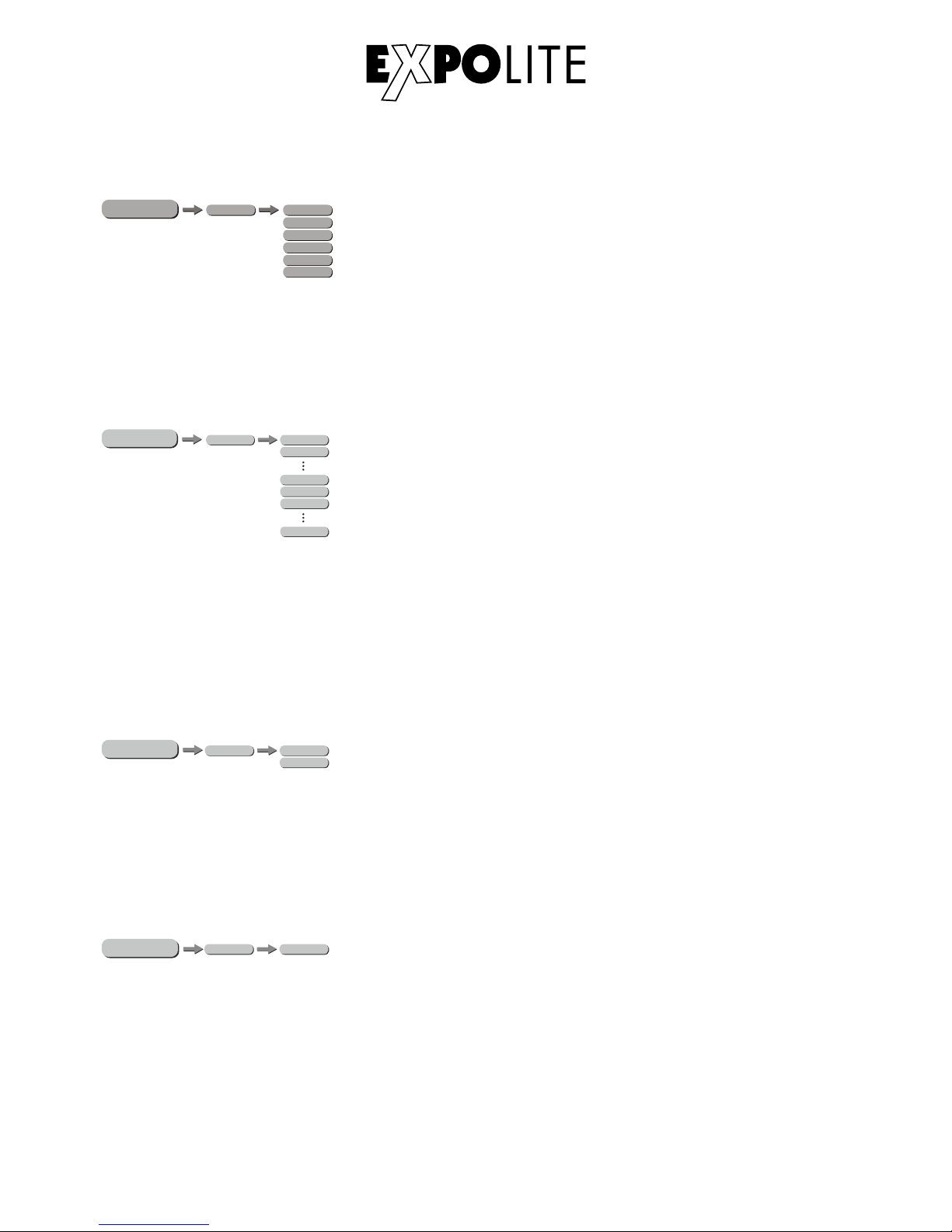
Edit Static Colors
In the menu, static colors for stand-alone operation are set in "STAT". These are mixed using the
DMX value scale 0-255 for red, green, blue, white and zoom as well as the strobe value 0-20Hz.
Activating Auto Programs
In the menu "AUTO", the automatic programs stored in the device are activated. The programs
"AT01" to "AT10" are permanently stored in the device. The programs "PR01" to "PR10" are
editable. This is described under "Editing User Programs". Automatic programs are transmitted
as master to connected slave devices. For master-slave operation, signals are sent via the DMX
line. This may disturb third devices.
Run Mode DMX / Slave
The operating mode is set in the menu "RUN". For operation on a DMX controller "DMX" must
be activated. For operation as a slave device, "SLAV" must be activated. In slave mode, the
device receives static colors or played automatic programs from a connected master device.
Setting DMX Adress
The DMX start address of the device is set in the menu under "DMX". This is retained even
when changing the personality.
E-25
MENU
AT.01
AT.02
AT.10
AUT O
PR. 01
PR. 02
PR. 10
MENU
RUN DMX
SLAV
MENU
D.( 001~5 12)
DMX
R.( 0~255 )
G.(0~255)
B.(0~255)
W.(0~255)
S.(0~20)
MENU
STAT
Z.( 0~255 )
Page 26
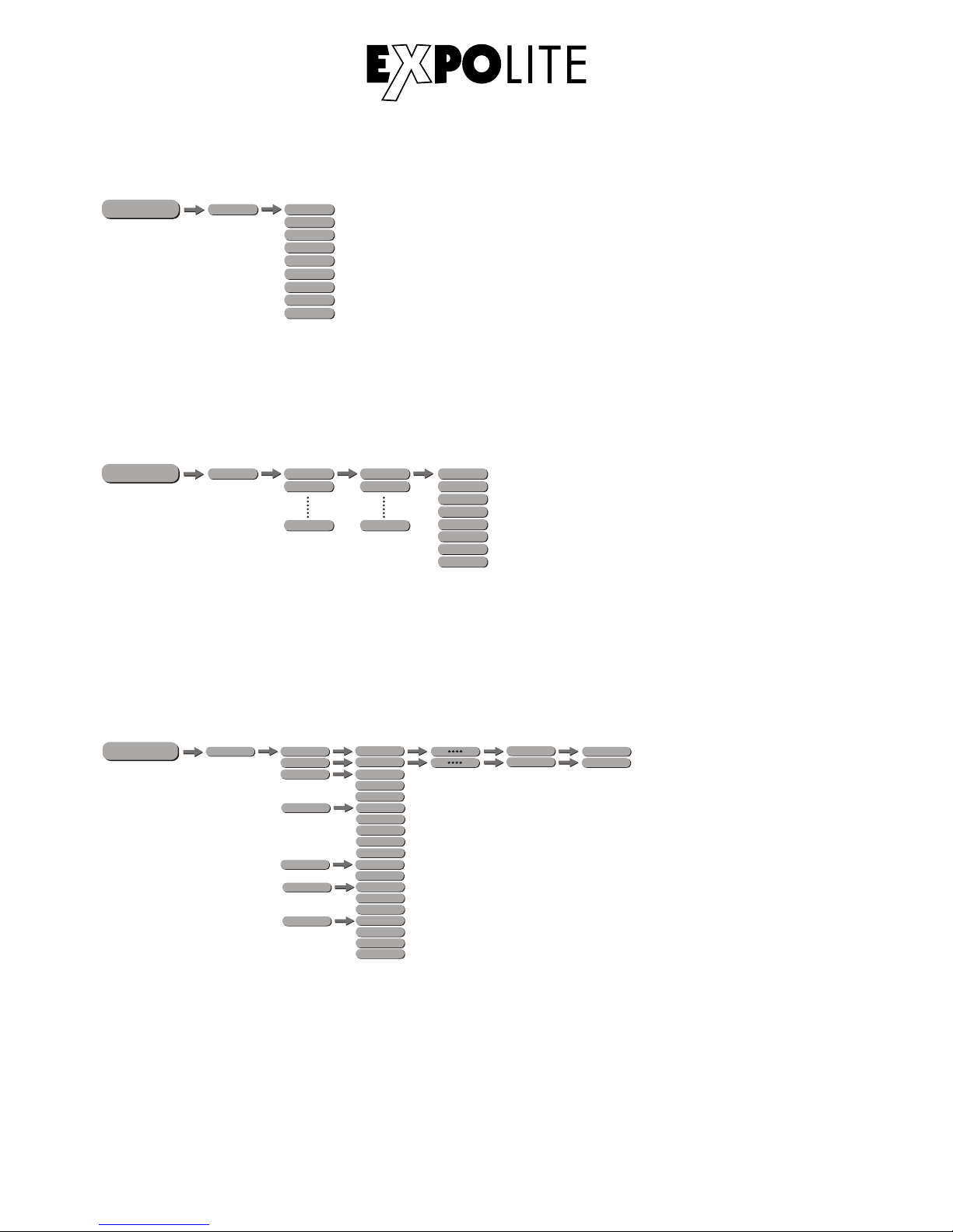
Personality
In the menu, the desired DMX personality is set in the "PERS" item. The personalities stored in
the sub-menu "RGB" are backwards compatible with the RGB version "TourLED 42 CM". The
channel assignment of the individual personalities is described in Chap. "Control via DMX512".
Edit User Programs
Advanced Settings
The user programs "PR01" to "PR10" are edited in the menu under "EDIT". Each program can
use up to 30 steps. Each step contains the parameters color "RGBW", strobe "0-20Hz", zoom,
duration the step "Time" and crossfade time "Fade". User programs can be transferred to other
devices as shown in „Advanced Settings“.
In the menu "SET" advanced device settings can be done. The password for settings is
"UP" - "DOWN" - "UP" - "DOWN" - "ENTER" and can not be changed.
"UPLD": The upload function transfers user programs to connected slave devices. These must
be set to slave in operating mode "RUN".
„REST“: Will do a complete reset and recall factory settings.
E-26
TOUR
ARC .1
ARC.2
AR1.D
AR2.S
AR2.D
PERS
HSV
MENU
TR1 6
AR2.Z
R.( 0~255 )
G.(0~255)
B.(0~255)
W.(0~255)
Z.(0~255)
T.(0~255)
F.(0~255)
PR.C1
PR.C2
PR.10
SC.01
SC.02
SC.30
EDIT
MENU
S.( 0~20)
MENU
SET
UPLD
REST
OFF
COLR
DIM 3
DIM1
DIM2
DIM4
DIM
RGBW
UC
OF F
PAS S
PASS
SEND
END
REST
END
BLAC
SAVE
DERR
POS2
POS1
ZOOM
BASE
CV3
CV2
CURV
CV1
OFF
Page 27
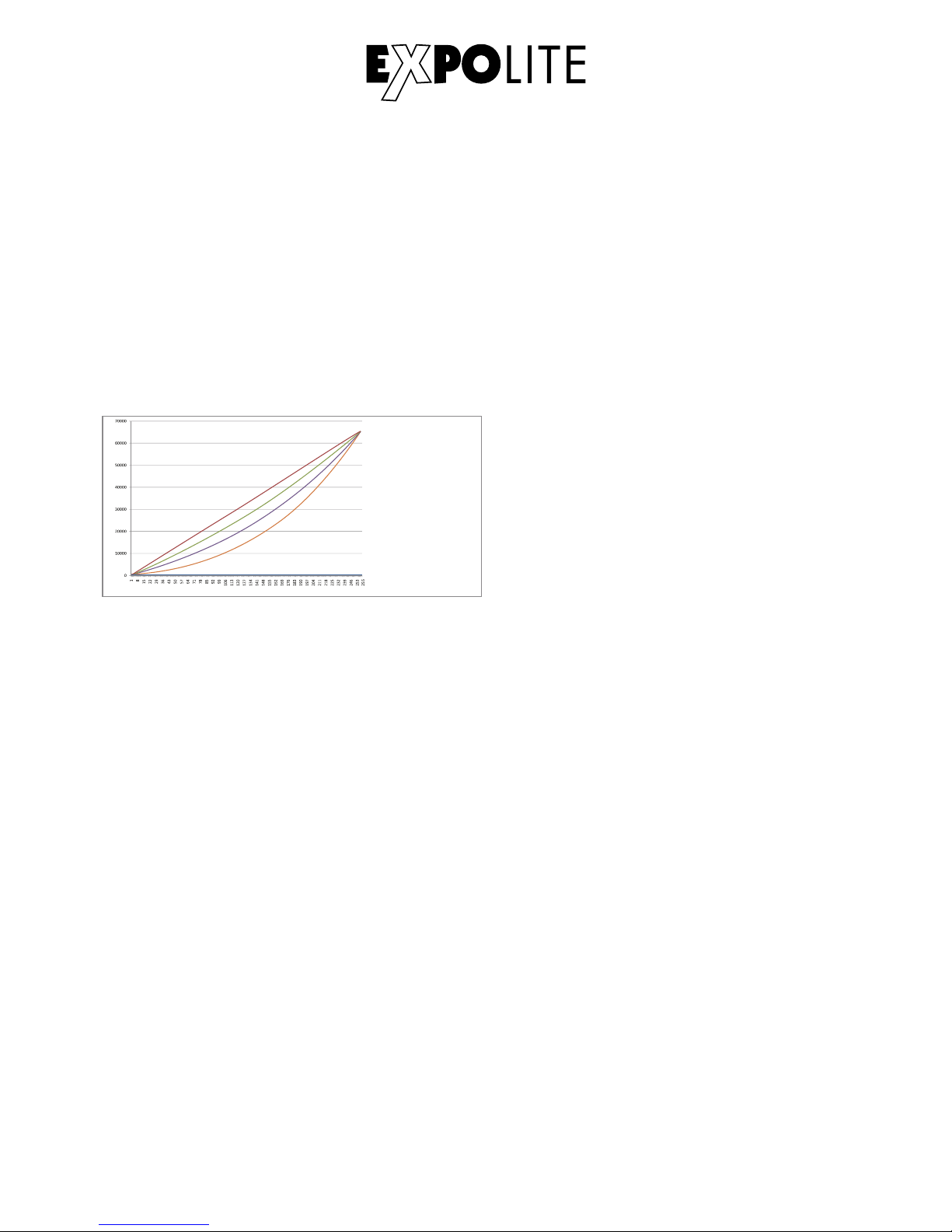
„COLR": In the Color menu, the color calibration is selected or deactivated. When "RGBW" is
selected, the maximum brightness values at DMX = 255 are limited to the values set in "CAL2."
When "UC" is selected the Uniform-Color factory calibration is used, which adjusts devices of
different generations. If the value is "OFF", the calibration is deactivated and the device reaches
the maximum brightness.
"DIM": Dim4 technology for halogen simulation. In the menu item "DIM" the dimmer speed is set.
These decay curves simulate the dimming of classic halogen bulbs. When "OFF", the device
reacts instantly.
„CURV“: In Curve Menu, the Dimmercurve ist set like shown below.
CURV dimming
1: OFF
2: Cv1
3: CV3
4: Cv4
1
2
3
4
(100 %)
"DERR": In the menu DMX-Error is set whether the device in case of a signal interrupt will hold
the last value "SAVE" or fades "BLAK".
„ZOOM": In Zoom Menu the Zoom is calibrated. The start and stop position is set with „POS1"
and „POS2". The „BASE“ Position is the default position after starting the unit.
E-27
Page 28
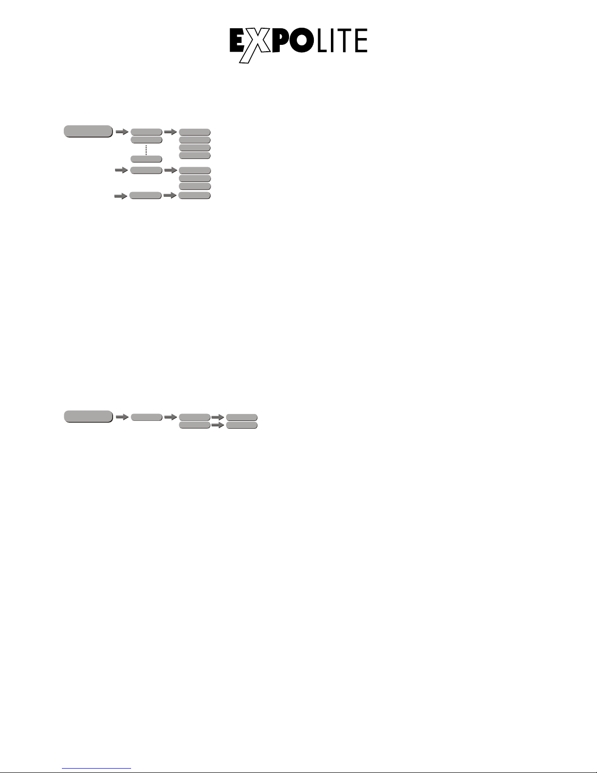
Calibration and Whiteadjustment
In the menu "WH.xx" the color temperatures for the white values are stored. These are mixed
from the parameters "RGBW".
In the menu "RGBW" a custom color calibration is stored which limits the maximum brightness
of the color channels at the DMX value "255".
NOTE: The maximum value can be limited to 0. In this case, a color channel does not respond
to a sent DMX value, which can be misinterpreted as a device error.
In the menu "CAL" all calibrations are reset to factory settings.
E-28
Zoom-Range
In the menu „ZOOM“ the zoomrange is limited. The set positions in this menu are the limits of
zoom, that can be controlled by DMX.
MENU
WH. 01
R. (0~255 )
WH. 02
G. (0~255 )
B.( 0~25 5)
W.(0~ 255)
WH. 11
RGB W
R. (0~2 55)
G.(0~255)
B.(0~255)
** **
CAL
MENU
ZOO M
POS.1
P( 0~25 5)
POS .2
P(0 ~25 5)
Page 29
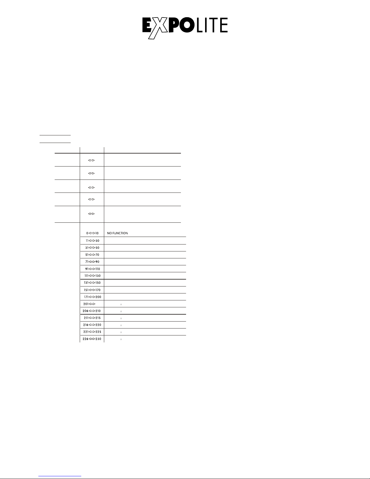
DMX-Channel assingment
This device has several DMX personalities. These different numbers of DMX channels are
occupied and the reaction of the device differs accordingly. There are 9 DMX personalities with
3, 3, 4, 4, 5, 6, 7, 12 and 17 channels selectable.
Using DMX512 Control
E-29
TOUR
1
2
0 255
3
4
0 255
0 255
0 255
5
0 255
CHAN NE L FUNCTIONVALUE
BLU E
WHITE
GREEN
(or FADE TIME when CUS.01-CUS.10 in CH8 is activated)
RED
(or STEP TIME when CUS.01-CUS.10 in CH8 is activated)
MASTER DIMMER
6
WHI TE1 320 0K
WHITE2 3400K
WHITE3 4200K
WHITE4 4900K
WHITE5 5600K
WHITE6 5900K
205
RED 100%/ GREEN 1 00%P/ BLUE1 00%/W HITE 10 0%
RED 0%/GREEN DOWN/BLUE 100%
RED UP/GREEN 0%/BLUE100%
RED100%/GREEN 0%/BLU EDOWN
RED100%/GREEN UP/BLUE UP
RED DOWN/GREEN DOWN/BLUE 100%
RED100%/GREEN UP/BLUE0%
RED DOWN/GREEN 100%/BLUE0%
RED 0%/GREEN 100%/BLUE UP
COL OR MACR O
Page 30
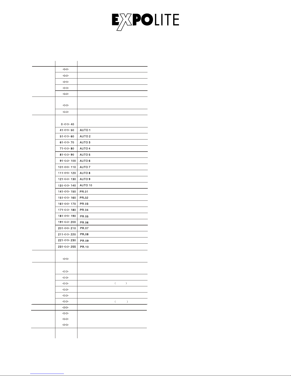
E-30
11
0 255
12
000 200
201 220
221 255
CHAN NEL FUNCTIONVALUE
7
8
0 10
1~20Hz
11
255
0 255
9
231 235
236 240
241 245
246 250
251 255
WHITE 7: 6500K
WHITE 8: 7200K
WHITE 9: 8000K
WHITE 10: 8500K
WHITE 11: 10000K
6
DIMMER SPEED
LINEAR DIMMER
NON LINEAR DIMMER 1 fastest
10 29
30 69
70 129
130 189
190 255
10
NON L INEAR D IMMER 2
NON LINEAR DIMMER 3
NON LINEAR DIMMER 4 slowest
NO FUNCTION
AUTO
NO FUNCTION
STROBE
AUTO SPEED ADJUSTMENT
When using CH 8,AU TO01-AUTO 10, th is function a ctiv ated
0 9
PRESE T DI MM ER S PEED FR OM D IS PLA Y ME NU
ZOO M
NO FUNCTION
ZOOM RESET
NO FUNCTION
Page 31
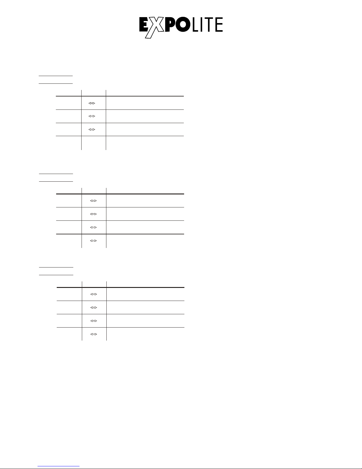
E-31
AR C .1
BLU E
1
2
0 25 5
CHAN NE L FUNCTIONVALUE
3
0 25 5
0 25 5
GREEN
RED
AR 1 .D
BLU E
1
2
0 25 5
CHAN NE L FUNCTIONVALUE
3
4
0 25 5
0 25 5
0 25 5
GRE EN
RED
MASTER DIMMER
AR C .2
BLU E
1
2
0 25 5
CHAN NE L FUNCTIONVALUE
3
4
0 25 5
0 25 5
0 25 5
GRE EN
RED
WHITE
Page 32
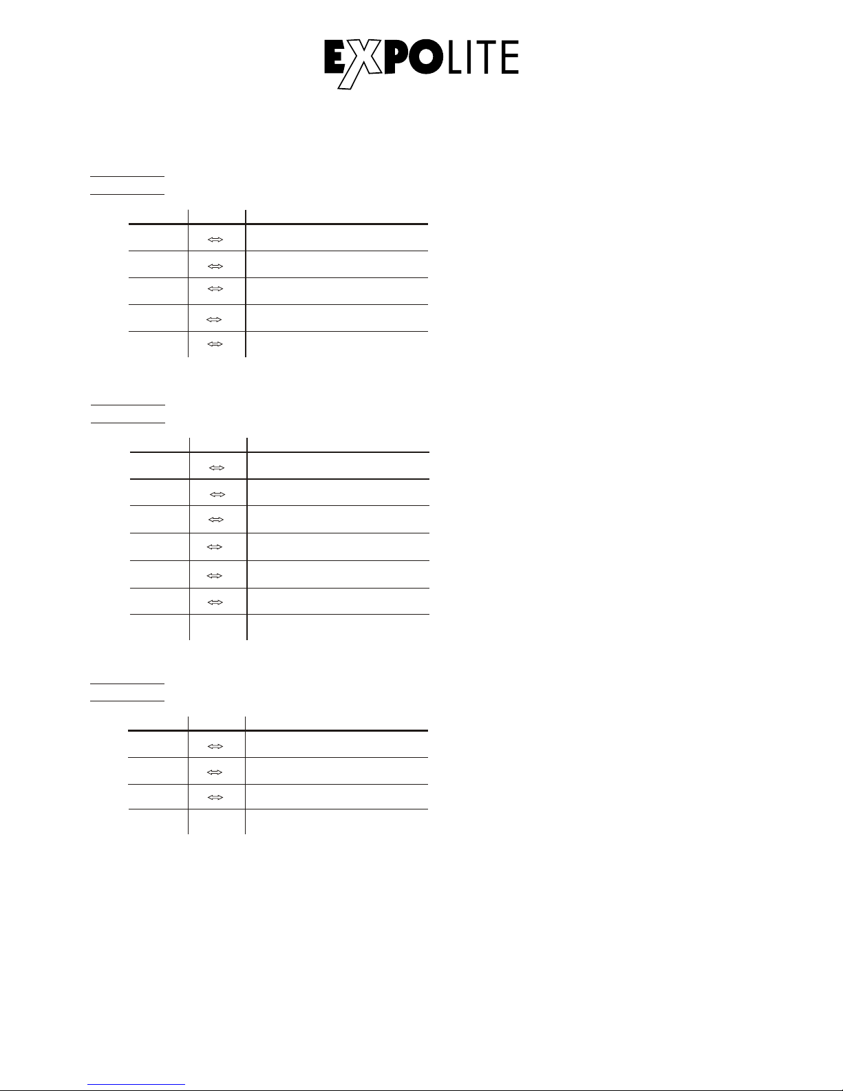
E-32
BLU E
3
4
0 2 55
0 2 55
GRE EN
WHITE
5
0 2 55
AR 2 .D
1
2
0 2 55
CHAN NE L FUNCTIONVALUE
0 2 55
RED
MASTER DIMMER
AR 2 .S
1
2
0 2 55
CHAN NE L FUNCTIONVALUE
3
0 2 55
0 2 55
HS V
1
2
0 2 55
CHAN NE L FUNCTIONVALUE
3
0 2 55
0 2 55
VALUE(0~100%)
SATURATION(0~100%)
HUE(0~100%)
4
5
6
0
0
0
255
255
255
BLUE
GREEN
RED
WHITE
MASTER DIMMER
STROBE
Page 33
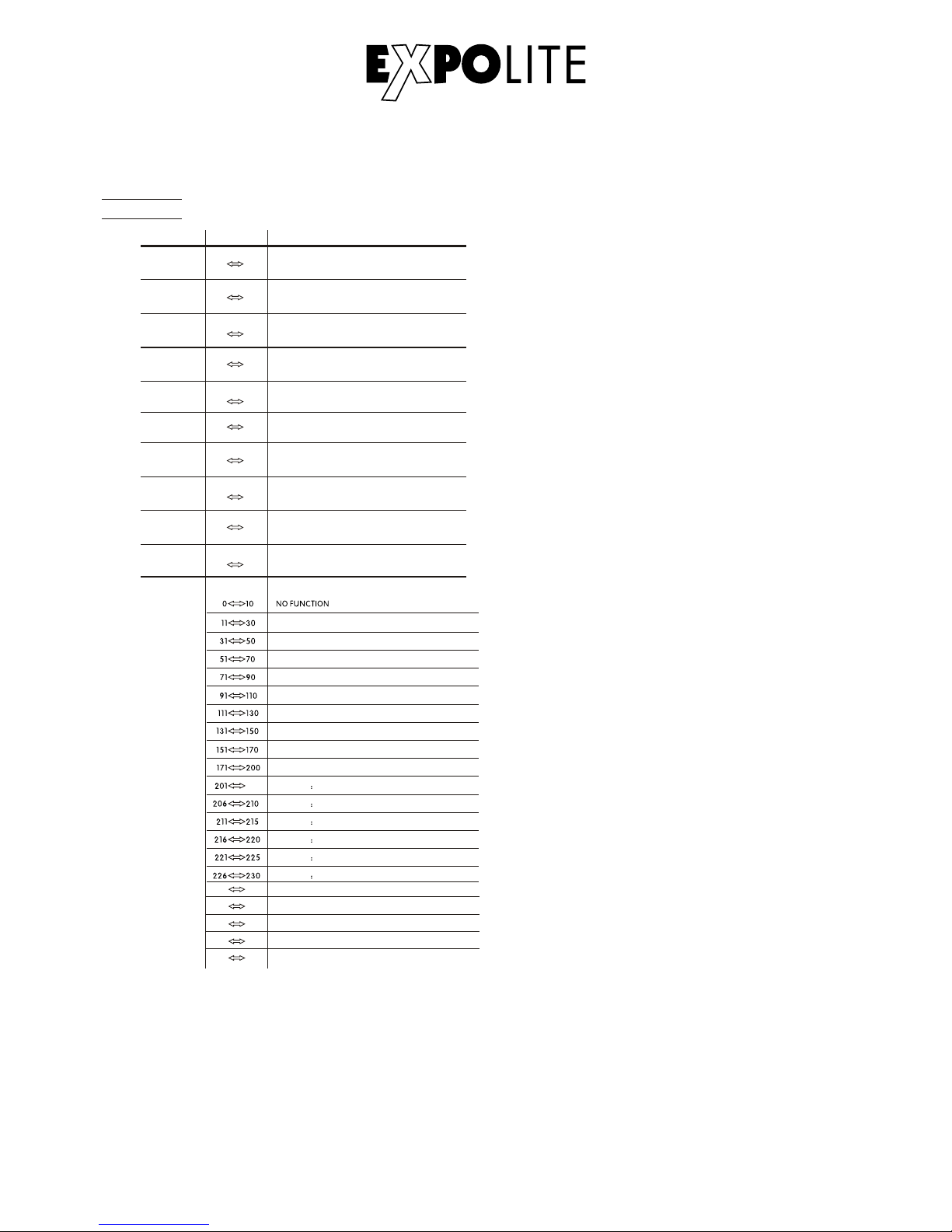
E-33
TR16
1
2
0 255
3
4
0 255
0 255
0 255
5
0 255
CHAN NE L FUNCTIONVALUE
MAS TER DIM MER
11
WHI TE1 320 0K
WHITE2 3400K
WHITE3 4200K
WHITE4 4900K
WHITE5 5600K
WHITE6 5900K
205
RED 100%/ GREEN 1 00%P/ BLUE1 00%/W HITE 10 0%
RED 0%/GREEN DOWN/BLUE 100%
RED UP/GREEN 0%/BLUE100%
RED100%/GREEN 0%/BLU EDOWN
RED100%/GREEN UP/BLUE UP
RED DOWN/GREEN DOWN/BLUE 100%
RED100%/GREEN UP/BLUE0%
RED DOWN/GREEN 100%/BLUE0%
RED 0%/GREEN 100%/BLUE UP
COL OR MACR O
6
7
0 255
8
9
0 255
0 255
0 255
10
0 255
GREEN
WHITE FINE
MASTER DIMMER FINE
RED
RED FINE
GREEN FINE
BLUE
BLUE FINE
WHITE
231 235
236 240
241 245
246 250
251 255
WHITE 7: 6500K
WHITE 8: 7200K
WHITE 9: 8000K
WHITE 10: 8500K
WHITE 11: 10000K
Page 34
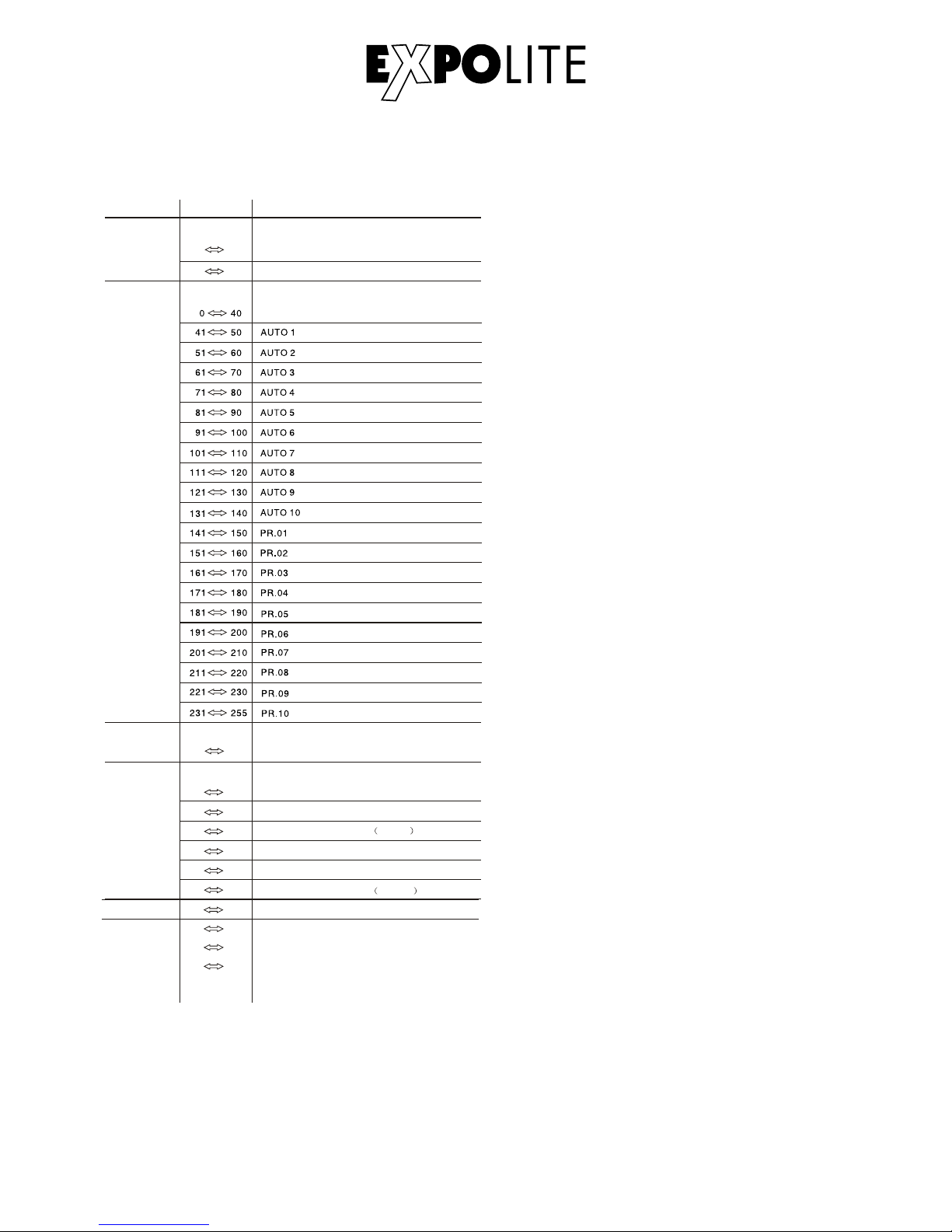
E-34
16
0 255
17
000 200
201 220
221 255
CHAN NEL FUNCTIONVALUE
12
13
0 10
1~20Hz
11
255
0 255
14
DIM MER SPE ED
LINEAR DIMMER
NON LINEAR DIMMER 1 fastest
10 29
30 69
70 129
130 189
190 255
15
NON L INEAR D IMMER 2
NON LINEAR DIMMER 3
NON LINEAR DIMMER 4 slowest
NO FUNCTION
STROBE
AUTO SPEED ADJUSTMENT
When using CH 13,A UTO01 -AUT O10, this fun ctio n activated
0 9
PRE SET DIM MER SPEED F RO M DISPL AY M EN U
ZOO M
NO FUNCTION
ZOOM RESET
NO FUNCTION
NO FU NC TI ON
AUTO
Page 35
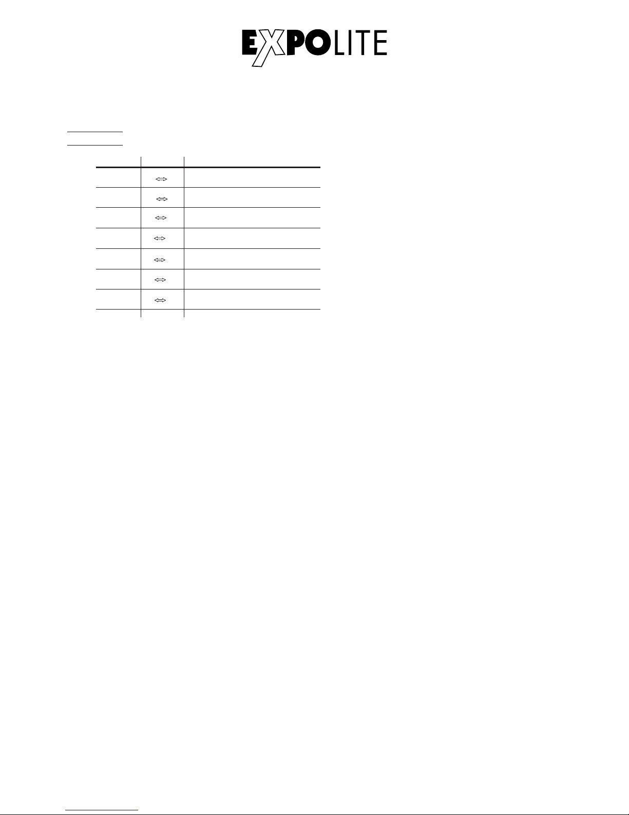
E-35
AR 2 .Z
1
2
0 2 55
CHAN NE L FUNCTIONVALUE
3
0 2 55
0 2 55
4
5
6
0
0
0
255
255
255
BLUE
GREEN
RED
WHITE
MASTER DIMMER
ZOOM
7
0 2 55
ZOOM RESET
Page 36

© 2018 by Focon Showtechnic Vertriebsgesellschaft mbH
 Loading...