

Page 1
OFFICE LINE
USER MANUAL
UM_EN
Date: 150525_02
R
Page 2

OFFICE LINE
2
CONTENT .....................................................................................................................................................................2
SYMBOL DESCRIPTION .......................................................................................................................................4
Hazard intensity levels ........................................................................................................................................................ 4
GENERAL ........................................................................................................................................................................5
Introduction .......................................................................................................................................................................... 5
General instructions ............................................................................................................................................................ 5
Warnings ................................................................................................................................................................................ 5
Precautions ............................................................................................................................................................................ 6
Intended use .......................................................................................................................................................................... 6
TECHNICAL SPECIFICATIONS ........................................................................................................................7
Leva ......................................................................................................................................................................................... 7
Accessories............................................................................................................................................................................ 7
Control/Pulser & Control/Pulser with grinder ............................................................................................................. 8
Accessories............................................................................................................................................................................ 8
OVERVIEW OF COMPONENTS ....................................................................................................................9
Leva ......................................................................................................................................................................................... 9
Control/Pulser .................................................................................................................................................................... 10
Control/Pulser with grinder ............................................................................................................................................ 11
DIMENSION SKETCH .......................................................................................................................................... 12
Leva ...................................................................................................................................................................................... 12
Control/Pulser ................................................................................................................................................................... 12
Control/Pulser with grinder ........................................................................................................................................... 13
TRANSPORT .............................................................................................................................................................14
Packaging .............................................................................................................................................................................. 14
Delivery inspection ............................................................................................................................................................ 14
INSTALLATION ....................................................................................................................................................... 14
Positioning ...........................................................................................................................................................................14
Electrical installation .......................................................................................................................................................... 15
Electrical connection types .............................................................................................................................................. 15
Water connection .............................................................................................................................................................16
Pressure and temperature ............................................................................................................................................... 16
Hydraulic connection types ............................................................................................................................................. 16
Filling the water tank ......................................................................................................................................................... 17
Connecting to the water mains ...................................................................................................................................... 18
Starting the machine ..........................................................................................................................................................18
The portalter set .............................................................................................................................................................19
Inserting the portalter in the group ............................................................................................................................19
Original Instructions
CONTENT
Page 3

OFFICE LINE
3
CONTENT
OPERATION ............................................................................................................................................................... 20
Espresso brewing ................................................................................................................................................................ 20
Steaming and frothing milk ............................................................................................................................................... 21
ESPRESSO MACHINE WITH BUILT-IN GRINDER ............................................................................ 22
Hot water dispensing ......................................................................................................................................................... 22
Before using the coffee grinder ....................................................................................................................................... 22
Adjusting the grinder coarseness .................................................................................................................................... 23
Dispensing a ground coffee dose .................................................................................................................................... 23
CLEANING AND MAINTENANCE ............................................................................................................ 24
Recharging the water softener ........................................................................................................................................ 24
Coffee machine cleaning .................................................................................................................................................... 25
Daily cleaning ....................................................................................................................................................................... 25
Weekly cleaning .................................................................................................................................................................. 25
Cleaning the brewing group and portalter ................................................................................................................. 26
Cleaning the gasket and shower plate ........................................................................................................................... 27
Additional handling of the machine................................................................................................................................. 28
STORAGE AND DISPOSAL OF MACHINE ..........................................................................................28
Storing the machine ............................................................................................................................................................ 28
Disposal of the machine .................................................................................................................................................... 28
PROGRAMMING ..................................................................................................................................................... 29
Touchpad .............................................................................................................................................................................. 29
Dosage programming of the drink buttons (Control models only). ....................................................................... 29
Normal mode ...................................................................................................................................................................... 30
Turning the thermostat and group boiler off/on ......................................................................................................... 30
Adjusting the group boiler temperature ....................................................................................................................... 30
Reset temperature to factory default ............................................................................................................................ 31
Thermostat alarms ............................................................................................................................................................. 31
TROUBLESHOOTING ......................................................................................................................................... 32
Quick Troubleshooting Guide ......................................................................................................................................... 32
Page 4

OFFICE LINE
4
SYMBOL DESCRIPTION
Hazard intensity levels
i
There are four different levels of notication intensity within this manual, as identied by signal words
DANGER, WARNING, IMPORTANT, and NOTE. The level of risk and importance of the notication
is determined by the following denitions. Always observe the warnings to ensure safety and prevent
potential injury and product damage.
Important:
Alerts against unsafe practices. Observe Important notications to ensure food safety, prevent
possible minor personal injury, or damage to the machine.
WARNING:
Indicates a potentially hazardous situation which, if the WARNING is ignored, could result in
serious injury or even death.
DANGER:
INDICATES A IMMINENTLY HAZARDOUS SITUATION WHICH, IF NOT AVOIDED, WILL
LIKELY RESULT IN SERIOUS INJURY AND EVEN DEATH.
Note:
Gives additional information which may be helpful during the operation, routine maintenance,
and cleaning of the machine.
Page 5

OFFICE LINE
5
GENERAL
Introduction
Thank you for choosing an OFFICE LINE espresso machine from EXPOBAR.
We hope you enjoy it !
Machine installation and certain maintenance
operations should only be performed by
qualified service personnel.
All safety instructions and warnings contained
in this manual should be observed to ensure
safe installation, use and maintenance.
Do not attempt to open or repair the machine
or access the interior. Repair should be
performed by an authorised workshop, by a
service centre, or by qualified service staff.
Do not remove operational or protective parts
requiring use of tools for removal.
Purchasers are liable for ensuring that users
have been trained to operate the machine
and have been informed of the potential risks
involved.
The installer will be held liable for all non-
authorised modification of the machine.
Non-authorised alteration or modification of
the machine will exempt the manufacturer of
all liability for damages and will invalidate the
warranty.
This manual refers to the machine as at the
time of sale. The commercial availability of
subsequent versions featuring modifications,
upgrades or adaptations does not oblige
the manufacturer to apply the same to this
machine, nor does it oblige it to update the
documentation supplied.
The manufacturer reserves the right to
withdraw currently available manuals whenever
it considers appropriate and reasonable.
General instructions
Warnings
Read this user manual carefully before starting
to use the machine.
This manual contains important instructions
regarding safe intended use of the machine.
Do not discard this manual, it will be useful for
future reference. If damaged or lost, request a
copy from the manufacturer.
Install the machine in a horizontal position and
away from heat sources and flammable objects.
This machine should only be installed on a
water-resistant work surface that is capable of
adequately supporting the machine’s weight.
Place the machine in a location accessible only
to personnel trained to operate it.
Keep all hazardous packaging materials, such as
plastic bags, styrofoam, and staples, out of reach
of children.
Plug the machine into a properly installed, earth
grounded electrical outlet with line voltage that
matches the specifications for the machine.
Ensure that the power supply voltage does not
fluctuate by more than 6%.
Position the power cable so that users cannot
trip over it. Keep the power cable away from
sharp edges and heat sources.
Children should never be allowed to play with
the machine.
This appliance is not suitable for installation in
an area where a pressure washer may be used.
Do not use the machine outdoors, where
it would be exposed to severe weather or
extreme temperatures..
If the power cable is damaged, it may only be
replaced by the manufacturer or its approved
service technician.
Do not remove or disable any of the
mechanical, electrical, or thermal protection
safety equipment.
Note:
The manufacturer is not liable for damage to persons or property resulting from failure to
follow the instructions and warnings listed below when installing and using this machine.
Page 6

OFFICE LINE
6
GENERAL
Precautions
Intended use
In case of emergency, (e.g., the machine catches
fire or becomes unusually hot or noisy),
disconnect the power immediately and turn off
the water supply.
If the machine is not going to be used for an
extended period of time, disconnect the power.
When disconnecting the power, pull the plug
rather than the cable.
When packed for storage, store the machine
in a dry place with an ambient temperature
above 5ºC. Boxes may be stacked up to three
units high of the same model. Do not place
other heavy items on top of the box.
If the machine is likely to be exposed to
temperatures below 0ºC during handling and
transport, make sure that service personnel
empty the boiler and water system. (The
machine’s boiler and water system is empty
when delivered from the factory.)
To ensure fault-free machine operation, only
use manufacturer-approved replacement parts
and accessories.
The coffee machine has been designed and
manufactured to make espresso coffee and
other hot drinks (e.g., steaming and frothing
milk). Do not use it for any other purpose.
The machine is intended to be used by trained
personnel for preparing foodstuffs.
This machine is not intended for use in
industrial kitchens, domestic kitchens, or similar
locations.
The manufacturer will not be held liable
for damage to persons or property due
to incorrect, improper or negligent use by
nonprofessional personnel.
To ensure optimal performance, install the
machine in a location where these parameters
will not be exceeded:
- Maximum permissible inlet water pressure:
600 KPa (6 Bar)
- Minimum permissible inlet water pressure:
200 KPa (2 Bar)
- Maximum inlet water temperature: 40ºC
- Ambient temp. maintained between:
+10ºC / (min.) and +40ºC (max.).
Before performing maintenance and/or moving
the machine, disconnect the machine from the
power supply and wait for it to cool down.
Do not place any liquids on the machine.
This appliance must not be cleaned with a
pressure washer.
Never immerse the machine, plug or power
cable in water, as there is a risk of electric
shock.
Do not touch the machine’s hot surfaces or
dispensing equipment.
Do not touch the machine if your hands or feet are
wet.
Do not operate the machine if any part except
the dispensing equipment is wet.
Place the machine out of reach of children.
This appliance can be used by children from
age 8 and above and persons with reduced
physical, sensory, or mental capabilities or lack
of experience and knowledge if they have been
given supervision or instruction concerning use
of the appliance in a safe way and understand
the hazards involved.
Children shall not play with the appliance.
Cleaning and user maintenance shall not be
made by children without supervision.
Do not use the machine if the power cable
or plug is damaged, or the machine has been
dropped. Contact a service technician for
repairs or to ensure that it is safe for use.
Do not block the vents with rags or other
objects.
Do not insert foreign objects into the vents.
Check the drain regularly to make sure that
waste water is emptying properly.
Page 7

OFFICE LINE
7
Accessories
TECHNICAL SPECIFICATIONS
Leva
MODEL
2-spout
portalter
Filter
basket
Coffee
spoon
Inlet
hose
Cleaning
membrane
Drain tube Tamper
Water
softener
cartrge.
Leva
-
Leva
2 boiler
1 unit
1 unit
each
1 unit
1 unit
(mains
connection
models
only)
1 unit
1 unit
(mains
connection
models
only)
1 unit 2 units
7 grams
14 grams
SPECIFICATIONS
MODEL
Leva 1 boiler Leva 2 boilers
Steam wand
1 unit
Hot water outlet
1 unit
Group
1 unit
Built-in grinder
No
Temperature control
Pressurestat regulated Pressurestat & PID regulator
Width, height, depth
16.9x10.2x18.1 in. / 430x260x460 mm
Boiler volume (L)
1.5 1.5 + 1.5
Water tank volume (L)
2.75
Power supply options
120V~ 1200W 60Hz
240V~ 1950W 60Hz
Water connection
Female 3/8” thread
Machine weight
55.8 lbs / 25.3 kg 62.4 lbs / 28.3 kg
Steam boiler operating press
11.6-18.8psi / 0.8-1.3 bar
Ambient noise
< 70 dB
21 in. /
55 cm
59 in. /
150 cm
Page 8

OFFICE LINE
8
Accessories
TECHNICAL SPECIFICATIONS
Control/Pulser & Control/Pulser with grinder
SPECIFICATIONS
MODEL
Control & Pulser
1 boiler
Control & Pulser
1 boiler w/ grinder
Steam wand 1 unit
1 unit
Hot water outlet 1 unit
1 unit
Group 1 unit
1 unit
Built-in grinder
No Yes
Temperature control
Pressurestat
regulated
Pressurestat
regulated
Width, height, depth
21.9x10.2x18.1 in.
555x260x460 mm
26.8x16.5x18.1 in.
680x420x460 mm
Boiler volume (L)
1.5 1.5
Water tank volume (L)
2.75 2.75
Power supply options
120V~ 1200W 60Hz 120V~ 1310W 60Hz
240V~ 1950W 60Hz 240V~ 2050W 60Hz
Water connection Female 3/8” thread Female 3/8” thread
Machine weight
37.5 lbs / 17.0 kg 59.5 lbs / 27 kg
Steam boiler operating press Between 11.6 and 18.9 psi /
0.8 and 1.3 bar
Ambient noise
< 70 db
MODEL
2-spout
portalter
Filter
basket
Coffee
spoon
Inlet
hose
Cleaning
membrane
Drain tube Tamper
Water
Softener
Cartrge.
Control
& Pulser
-
Control
& Pulser w/
Grinder
1 unit 2 units 1 unit
1 unit
(mains
con-
nection
models
only)
1 unit
1 unit
(grinder
models
only)
1 unit 2 units
7 grams
14 grams
21 in. /
55 cm
59 in. /
150 cm
Page 9
OFFICE LINE
9
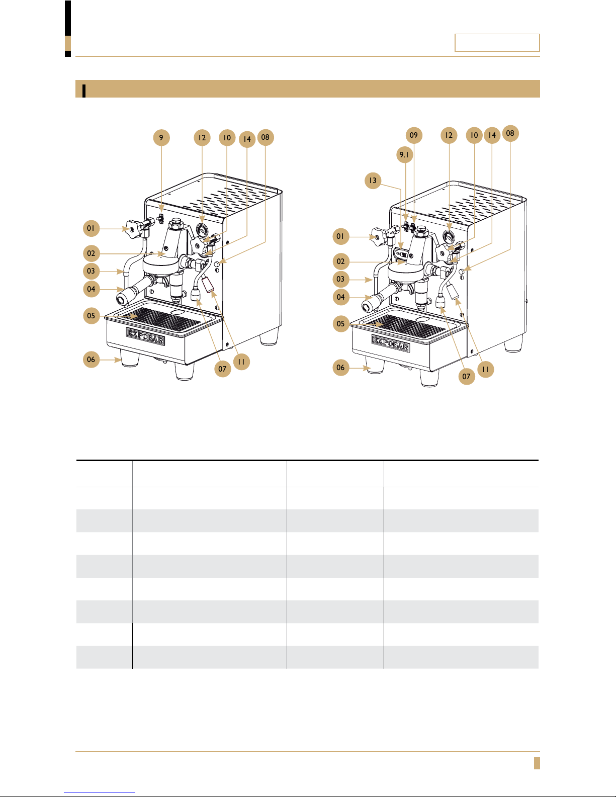
OVERVIEW OF COMPONENTS
Leva
POS. Description POS. Description
1 Steam tap 9 Main switch
2 Brewing group 9.1 Water-steam boiler switch
3 Steam wand 10 Hot water tap
4 Porta lter 11 Brewing lever
5 Removable drip tray 12 Steam manometer
6 Adjustable leg 13 Temperature control display
7 Hot water outlet 14 Brew manometer
8 Heating element light
Leva
Leva 2 boiler
010107
07
11
11
10
14
121309
9.1
08
010102
02
03
03
040405
05
06
06
10129
14
08
Page 10
OFFICE LINE
10
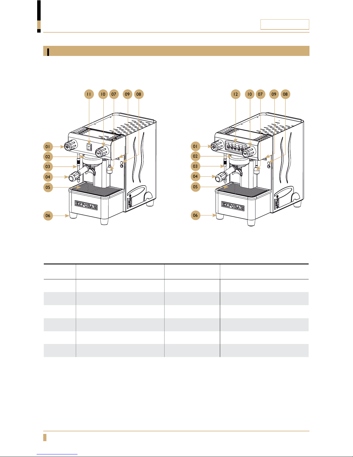
OVERVIEW OF COMPONENTS
Control/Pulser
POS. Description POS. Description
1 Steam tap 7 Hot water outlet
2 Brewing group 8 Heating element light
3 Steam wand 9 Main switch
4 Porta lter 10 Hot water tap
5 Removable drip tray 11 Brewing switch
6 Adjustable leg 12 Electronic control panel
Pulser
Control
01
01
11
12
010102
02
030305
05
06
06
04
04
07070909101008
08
Page 11

OFFICE LINE
11
11111110
10
2
8
4
3
9
6
5
7
OVERVIEW OF COMPONENTS
Control/Pulser with grinder
Pulser with grinder Control with grinder
POS. Description POS. Description
1 Steam tap 7 Hot water outlet
2 Brewing group 8 Heating element light
3 Steam wand 9 Main switch
4 Porta lter 10 Hot water tap
5 Removable drip tray 11 Brewing switch
6 Adjustable leg 12 Electronic control panel
2
8
4
3
9
6
5
7
Page 12

OFFICE LINE
12
DIMENSION SKETCH
Model A B C
Leva & Leva 2 boiler 260 mm 460 mm 430 mm
Leva
A
C
B
Model A B C
Control & Pulser
250 mm 420 mm 410 mm
A
C
B
Control/Pulser
Page 13

OFFICE LINE
13
DIMENSION SKETCH
Control/Pulser with grinder
Model A B C D
Control with grinder
420 mm 460 mm 560 mm 680 mm
Pulser with grinder
420 mm 460 mm 560 mm 680 mm
A
C
D
B
Page 14

OFFICE LINE
14
INSTALLATION
TRANSPORT
Positioning
Packaging
Delivery inspection
MIN. 30 cm
MIN. 10 cm
The machine is shipped in a custom-designed carton which utilizes model-specific polystyrene
cushions to protect it from damage.
The machine’s carton features standardized handling symbols to explain proper shipping and
storage methods.
The machine must remain in a horizontal position during the transport. Do not store or handle the
machine except on its feet.
During transport protect the carton and machine from impact drops, crushing, shocks, moisture
and exposure to extreme temperature.
Upon receipt and delivery ensure that the machine is in the exact condition described in the
enclosed documentation, and that all accessories are included. Missing items should be reported to
the manufacturer or dealer immediately.
Damage caused during transport should be reported to the shipping agent and the machine’s
distributor immediately.
Packaging materials are potentially dangerous and should be kept away from children.
The carton and all packing materials are recyclable and should be returned to a recycling center for
disposal.
i
Install the machine on a level, sturdy, and water-resistant
surface approximately 110cm above floor level for ease of
access and usage.
Adjust the feet to ensure that it dispenses coffee evenly to
all cups.
Ensure enough free space is available above (>30cm) and
behind (>10cm) the machine to ensure easy cleaning and
maintenance and adequate ventilation.
Do not install the machine if it is wet or damp. Allow it to
dry completely and ask a service technician to ensure that
none of the electrical components have been affected.
Note:
Leave an air gap of approximately 30cm above
the machine and 10cm behind it to ensure
adequate ventilation.
Page 15

OFFICE LINE
15
INSTALLATION
Electrical installation
Electrical connection types
The machine should only be connected to the power supply by qualified
personnel. The following safety instructions should be obeyed at all times:
Ensure that the electrical requirements stated on the TECHNICAL
SPECIFICATIONS (pages 7 - 8) match the specifications of the power
supply at the outlet.
Ensure that the domestic electrical supply where the machine is being
installed is rated for and able to provide the power required by the
machine. Insufficient power supply, wiring, grounding, or insulation can result
in overheating and possibility of fire.
The coffee machine must be connected to an earth grounded electrical
outlet that complies with the regulations in force in the country of
installation.
Ensure that a circuit breaker engineered for the power consumption of the
machine is installed to protect the domestic electrical supply, as specified on
the ratings plate located under the drip tray.
Do not connect the machine to the domestic power supply via extension
cords, plug adapters, or shared outlets.
The manufacturer will not be held liable for damage to persons, animals or
property resulting from incorrect installation of the coffee machine.
DANGER!
If the power cable or plug is damaged, it must be replaced by the manufacturer, distributor, or
its approved service technician in order to avoid RISK OF SERIOUS INJURY OR DEATH!
Connect the machine per the instructions and voltage information shown on the ratings plate.
NEUTRAL
PHASE
Supply
Blue
Brown
Yellow/Green
VOLTAGE TYPE:
220-240Vac Ph+N
PHASE
PHASE
Supply
Blue
Brown
Yellow/Green
NEUTRAL
PHASE
Supply
White
Black
Green
VOLTAGE TYPE:
220-240Vac 2Ph
VOLTAGE TYPE:
125Vac Ph+N
Page 16

OFFICE LINE
16
INSTALLATION
Water connection
Pressure and temperature
Relationship between boiler pressure and temperature
Standard pressure and temperature
0.7
110
115
120
125
0.8 0.9 1 1.1 1.2
o
C
BAR
Fig. 01
Connecting the machine to the domestic water supply must be performed by a qualied person.
Purge at least 20 liters of water from the domestic water supply before connecting the machine to it to ush
out any debris that may be in the plumbing system that would otherwise accumulate inside the boilers.
The domestic plumbing system should be tted with a brass 3/8” male pipe tting and an in-line
shut-off valve. Connect the 180cm water inlet hose included with the machine to the domestic water
supply and tighten the line ttings with a wrench.
Only use safe drinking water with a hardness rating between 5ºfH and 8ºfH (French hardness
degrees) or 20 to 32 ppm (parts per million as calcium). If the hardness value is below this limit,
corrosion of hydraulic components is likely. If the value is higher, lime-scaling inside the boiler will
occur. In both cases, the proper function of the machine and quality and taste of the coffee will be
negatively affected.
If necessary, connect the machine to a water softener to reduce water hardness using the exible
55cm hose included in the accessory box.
Connect one end of the corrugated drain tube to the drain cup in the machine, connect the other
end to the plumbing drainage system in the installation area.
Boiler pressure is directly related to water temperature (g. 01).
Machines tted with a pressure gauge will display the boiler pressure, while machines is tted with
a digital display it will indicate water temperature.
Important:
Only use the hoses supplied with the machine. Never reuse damaged hoses.
Ensure that the drainage tube is not twisted and that it is below the level of the drain cup.
Hydraulic connection types
This machine is offered with three options for hydraulic connection:
Machine intended for water mains connection.
Machine with internal water tank.
Machine with internal water tank and water mains connection.
Check the machine ratings plate to confirm which arrangement the specific machine is
equipped as.
Page 17

OFFICE LINE
17
INSTALLATION
Filling the water tank
Option 1:
Remove the top panel/cup warming tray.
Remove the water inlet tube and water softener unit, then
remove the water tank.
Fill the tank with clean, fresh drinking water (max. volume = 2.75L).
Replace the water tank in the machine, then replace the softener unit, with
the inlet side pointing down.
Replace the top panel/cup warming tray.
When the boiler is lled and heated, the machine is ready for use.
Option 2:
Remove the top panel/cup warming tray.
Using a pitcher, carefully ll the tank with clean, fresh drinking water (max.
volume = 2.75L). Avoid spills inside the machine.
Replace the top panel/cup warming tray.
When the boiler is lled and heated, the machine is ready for use.
DANGER!
Avoid spills inside the machine. If spills occur, turn the machine off and unplug the
power supply until the machine is completely dry to avoid RISK OF SHOCKS.
i
i
Note:
The machine has a microswitch located below the water tank to automatically stop the
machine’s pump when the tank is empty. Therefore, the water tank should only be removed and
relled when espresso is not being brewed.
Note:
Always use fresh water with a pH water with a hardness rating between 5ºfH and 8ºfH (French
hardness degrees) or 20 to 32 ppm (parts per million as calcium) to ensure great tasting coffee
and to prevent limescaling.
Page 18

OFFICE LINE
18
Attach the included 1/2’ water inlet hose to the bottom of the machine (elbow end to machine,
straight end to mains) and torque both ttings with a wrench.
Open the water valve located on the bottom of the machine (see images below for positioning).
When the boiler is lled and heated, it is ready for use.
Connecting to the water mains
1/2” water
connection elbow
Back of
machine.
1-2 kg bottle,
or similar
Valve set to use
water mains only.
Valve set to use
water tank only.
Important:
To prevent limescale build up in the
boiler and other components, a watersoftening system must be installed in-line
ahead of the machine.
INSTALLATION
This section applies to models with the optional water mains connection.
Starting the machine
Fill the water tank or open the water mains supply valve.
Turn on the main power switch.
Press a drink button at the control panel or raise the group lever then wait until water comes out
continuously. This ensures that the heat exchanger in the machine is being correctly lled.
Open the steam tap to release any air trapped in the boiler.
The red lamp indicates that the boiler is heating. The lamp switches off automatically when the
machine reaches operating temperature and is ready to use.
i
Note:
For models which have both water tank
and water mains connection, the water tank
must be removed and stored and a 1-2 kg
water-proof, heat-resistant object (such as
a sealed, lled plastic bottle) must be put
in its place to ensure the pump-control
microswitch remains on. Failure to weigh
down the microswitch will prevent the
machine from lling the boiler.
Page 19

OFFICE LINE
19
INSTALLATION
The portafilter set
Inserting the portafilter in the group
Filter basket locking spring
Filter basket
Portafilter spring channel
Portafilter & filter basket
for double espresso (14g)
Align the portafilter's two flanges with
the two slots in the group housing.
Insert the portafilter and rotate it counterclockwise until
the handle is approximately perpendicular to the face of
the coffee machine.
Correct
position.
Portalter not
fully inserted.
Group gasket is
worn out, please
replace.
Page 20

OFFICE LINE
20
OPERATION
Espresso brewing
01 02
03 04 05
06
Important:
Always keep the
portalter inserted
in the group to keep
it warm. This is very
important to maintain
an optimal temperature
to make the best
espresso possible.
Unlock and remove the portafilter
from the group head.
Compress the coffee with the
coffee tamper.
Place one or two cups
beneath the outlet spouts.
Select the desired option from the drink buttons or raise the group lever.
Insert the filled portafilter into the
group head and lock it into the
correct position.
Fill the lter basket of the
portalter with espresso
powder (the amount may
differ depending of the lter
basket size). For best result
use freshly ground espresso
beans.
WARNING!
Never try to open the portalter while the machine is in operation! The pressurised hot water
could cause scalding or serious injury. After dispensing has nished, wait at least 3 seconds before
removing the portalter.
Page 21

OFFICE LINE
21
OPERATION
Steaming and frothing milk
01
02
04
03
05
Steaming
Frothing
Place the steam wand over the drip tray
and open the steam tap for a few seconds
to allow condensed water to be ejected.
Close the steam lever when only steam
comes out.
Open the steam tap again to begin steaming or frothing
the milk. Do not remove the milk pitcher while steaming.
Once the milk reaches the
desired temperature, close the
tap and remove the pitcher.
Immerse the steam wand into the milk, making sure
the wand tip is submerged.
After the process is finished, position the steam wand
over the drip tray and open the steam tap for a few
seconds to eject any milk remaining in the wand.
Close the tap and then wipe down the outside of
the steam wand with a damp cloth to prevent nozzle
blockage and to keep it clean. Leaving milk in or on
the wand will affect the taste of later drinks.
WARNING!
Do not allow the steam wand to extend out
of the milk when the lever is open, it may
cause serious burns and injuries.
Page 22

OFFICE LINE
22
OPERATION
Hot water dispensing
Place a jug (or similar) under the hot water outlet.
Open the hot water tap.
Close the tap as soon as the machine has
dispensed the desired amount of water.
WARNING!
Never expose hands and ngers directly
under the water outlet during operation
to avoid scalding or serious burns.
ESPRESSO MACHINE WITH BUILT-IN GRINDER
Before using the coffee grinder
Pos PART NAME
1
BEAN HOPPER LID
2
BEAN HOPPER
3
BEAN STOP
4
GRINDING ADJUSTMENT DISK
5
COFFEE TAMPER
6
GRINDER POWER SWITCH
7
GRINDER COFFEE OUTLET
8
PORTA FILTER HOLDER
9
GRINDER ACTIVATOR
2
1
3
5
8
4
6
7
9
Check that the bean hopper (2) is correctly fitted in place.
Lift up the bean hopper lid (1), fill the bean hopper (2) with coffee beans and close it again.
Open the bean stop (3) to allow the coffee beans to flow into the grinder.
Page 23

OFFICE LINE
23
ESPRESSO MACHINE WITH BUILT-IN GRINDER
Dispensing a ground coffee dose
Adjusting the grinder coarseness
Fine Coarse
Place the portalter on the portalter holder (9), below the
ground coffee outlet.
Press the portalter against the grinder activator (10),
ground coffee will dispense automatically.
Release the pressure on the activator when the desired
amount is reached.
Place the portalter under the coffee tamper (6) and push it
up to compact the coffee.
For a finer grind:
Hold down the grinder trigger while slowly rotating the
adjuster to the right. When the desired grind is achieved
release the trigger.
For a courser grind:
Hold down the grinder trigger while slowly rotating the
adjustment disk (4) to the left. When the desired grind is
achieved release the trigger.
Important:
You should only adjust the coarseness when the grinder is turned off.
i
Note:
If when brewing espresso, if it comes out very slow, the grinder is set too ne. If it comes out too
quickly and coffee appears pale and weak, it is too course. Espresso should come out with a slow,
thin and continuous ow and dark color.
Page 24

OFFICE LINE
24
CLEANING AND MAINTENANCE
Recharging the water softener
Turn the machine off at the main power switch.
Remove the top panel/cup warming tray.
Remove the water inlet hose and water softener unit.
Place the water softener unit in a container of 1% salt water solution (99% clean water + 1% plain
table salt) for 10 minutes. The hose does not need to be disconnected.
After recharging, remove the water softener unit and dry the outside with a clean cloth. The water
inside the unit may remain.
Replace the water softener unit in the water tank and make sure the water tank is filled to dilute
any remaining salt water.
Replace the top panel/cup warming tray and turn on the main power switch. The machine is now
ready for use.
Soak in 1% saltwater
solution for 10 minutes.
i
Note:
This section only
applies to water
tank models.
Page 25

OFFICE LINE
25
Coffee machine cleaning
Important:
To keep the machine looking and working like new, you should always follow the cleaning
and care instructions provided in this manual.
Always turn off the main power switch when cleaning the exterior of the machine.
All external surfaces should be cleaned with a damp, lint-free cloth that will not scratch the
machine.
Do not use aggressive cleaning detergents, solvents or degreasers. These can damage the
surfaces, and plastic and rubber parts, and leave unwanted residue.
Important:
Each day, or 8 hours after dispensing the last coffee, the following cleaning tasks should be
performed to maintain the quality and performance of the water system:
Portafilter: Brew one espresso with the filter empty (around one minute) to flush it out
(dispose of this water).
Steam Wand: Position the wand over the drip tray and open the steam lever for one minute
to flush the wand.
Hot Water Outlet: Place a container under the water outlet and dispense water for 10
seconds (dispose of this water).
Daily cleaning
Weekly cleaning
Clean the brewing group and portafilter with professional cleaning powder (see page 26).
Clean the water tank once per week with detergent and a bottle brush under running water to
prevent bacteria build-up. Rinse thoroughly and dry the outside before refilling and replacing it in
the machine.
Rinse the brewing group, shower plate, and portafilter with hot water for 15 seconds (page 27).
Clean the external surfaces of the machine with a damp cloth, paying special attention to the
stainless steel parts.
Clean the steam wand and the water tap. Be sure that the nozzles are not clogged or partially
blocked with milk or other residue. If it’s necessary to remove them for cleaning, be careful not to
deform or damage any of the components during removal.
Clean the dip tray and the stainless steel insert grid under running water with a brush.
Clean the drain cup by slowly pouring one liter of warm water into it to dissolve and remove the
coffee residue that accumulates inside the drain cup and hose.
CLEANING AND MAINTENANCE
Page 26

OFFICE LINE
26
CLEANING AND MAINTENANCE
Cleaning the brewing group and portafilter
Unlock and remove the portafilter from the group head.
Place the cleaning membrane in the filter basket.
Fill the filter basket with professional cleaning powder for espresso coffee machines.
Lock the portafilter into the group head.
Ofce Control machines: To activate the auto-cleaning program turn off the machine’s main power
switch. Then press and hold the 2 Short Espressos button then turn on the main power
switch. Cleaning will start automatically. Release the 2 Short Espressos button.
Office Pulser machines: To activate the auto-cleaning program simply cycle the Brew button on
for 5 intervals of 10 seconds each.
Leva Pulser machines: To activate the auto-cleaning program simply raise the brew lever for 5
intervals of 10 seconds each.
Cleaning membrane
Espresso-machine
detergent
Note:
Only use professional cleaning
powder for espresso machines.
It’s available from your
distributor. Part no: 1104162
i
WARNING!
Never try to open the portalter while the machine is in operation! The pressurised hot
water could cause scalding or serious injury. After cleaning has nished, wait about 3
seconds before removing the portalter.
Important:
When the cleaning process is nished, remove the portalter and run water through
the group again to rinse out any residue. Repeat the cleaning process this time without
cleaning powder to remove any remaining residue. Store the cleaning membrane in a
convenient location for future use.
Note:
Rinse the group and portalter with hot water (using only the cleaning membrane and
hot water, no cleaning powder) each day that the machine is used.
Clean the group and portalter with cleaning powder once a week.
i
Page 27

OFFICE LINE
27
Cleaning the gasket and shower plate
While making espresso, coffee grounds will naturally accumulate on the group’s sealing surface.
Allowing an excessive amount of grounds to build up can prevent the portafilter from properly sealing
to the group head. In extreme cases, such as leaving a used portafilter in the group head for several
days, water can even become blocked from passing through the shower plate.
To prevent these problems, perform the following cleaning procedures daily:
Place the cleaning membrane in the lter basket (without detergent).
Insert the portalter in the group head, but do not tighten fully (the portalter should be loose).
Press the Continuous Dispensing button for Control machines, or press the brew button
for Pulser machines. For Leva machines, raise the brewing lever for 15 seconds.
Make an opening-closing movement of the portalter in place without closing it. Water will now
ow around the portalter, owing through the closing surface and cleaning it.
CLEANING AND MAINTENANCE
Coffee residue
requiring cleaning
Cleaning the gasket
Cleaning the shower plate
Shower plate
WARNING!
Take special care to avoid scalding when
performing this cleaning operation, as the hot
water used to clean the gasket will spill over
the sides of the portalter.
WARNING!
Do not fully tighten the portalter. If fully
tightened, high-pressure water may spray out
and cause scalding or serious injury.
Remove the portalter from the group head.
Clean the shower plate and group gasket with a soft brush to remove any coffee residue.
Page 28

OFFICE LINE
28
Additional handling of the machine
Storing the machine
Disposal of the machine
CLEANING AND MAINTENANCE
STORAGE AND DISPOSAL OF MACHINE
Always remove and insert the portalters
gently. Never use excessive force to try to
close the portalter. If the portalter does
not turn and lock into place without excessive
force this usually indicates that there is too
much coffee in the lter basket.
Important:
Do not place wet cups directly on the
cup shelf. Allowing water to drip into
the machine can cause mechanical and
electrical damage.
Before storage be sure to:
Perform all weekly and periodic cleaning procedures described in this manual (see pages 25-27).
Disconnect and roll up the power cord (this should be performed by a qualified person).
Disconnect the machine’s water inlet hose from the domestic water supply and drain the boilers (this
should be performed by a qualified person).
Clean the drip tray and exterior of the machine to remove any coffee or other residue.
Cover / re-pack the machine in its original carton and store it in a dry place where it will not be
exposed to extreme temperatures or humidity.
When returning the machine to service after long-term storage perform all weekly and periodic
cleaning procedures before use.
Disconnect and roll up the power cord (this should be performed by a qualified
person).
Disconnect the machine’s water inlet hose from the domestic water supply and
drain the boilers (this should be performed by a qualified person).
Pack up and ship/deliver the machine to an authorized recycling center.
Page 29

OFFICE LINE
29
For machines equipped with an electronic control panel (5 buttons per brewing group), the following
controls are available:
Volumetric control for four different espresso doses.
Time-controlled hot water dosage (on customer’s request).
Automatic filling and level control of the boiler.
Automatic switch off of the heating element at low water level (on customer’s request).
Brewing group auto-cleaning/descaling.
The control panel is by default programmed with 4 standard drink doses (these can be re-programmed
as desired) and one continuous brewing function. The four left-side buttons (1 short espresso – 1
long espresso – 2 short espressos – 2 long espressos) brew the programmed amount and then stop
automatically; the right-side button brews continually until stopped manually by pressing again.
Touchpad
Dosage programming of the drink buttons (Control models only).
PROGRAMMING
1 Long Espresso
1 Short Espresso
2 Short Espresso & Auto-cleaning
Programming &
Continuous Dispensing
2 Long Espressos
Press the Continuous Dispensing button for 4 seconds, it will begin to flash.
Within 5 seconds, press the button of the dispensing option that you want to program: 1 Short
Espresso, 1 Long Espresso, 2 Short Espressos or 2 Long Espressos. The lights on the selected drink
button and the Continuous button will remain on.
The group will start dispensing coffee. When the desired volume is reached in the cup, press the
selected drink button again to stop dispensing. This volume setting will be saved and the button’s light
will turn off. The Continuous button will remain illuminated.
Repeat this process for all of the dispensing options that you wish to reprogram.
If you only need to reprogram one of the dispensing options, follow the steps above and program just
that option. All of the other dispensing options will remain unchanged.
Important:
Always use a portalter lled with fresh coffee grounds for every new dose programmed.
Page 30

OFFICE LINE
30
On Leva Multiboiler machines the temperature of each group boiler can be programmed and adjusted
individually via the digital temperature adjusting system.
The temperature control is performed by a PID thermostat, which provides accurate and stable
temperature management for the group.
During normal mode, the temperature display shows
the current temperature of the group boiler. When
the boiler’s heating element is working and water is
heating up, a small blue dot will illuminate to indicate this
function.
Note:
Adjust the group boiler’s temperature up with the
button and down with button.
To turn the thermostat and its group boiler off, press and hold
the
button for 2 seconds. The thermostat selected will be
disconnected, “OFF” will be displayed, and the group will start to
cool down.
To connect the thermostat:
If the thermostat is “OFF”, press either the or
button. The thermostat will be turned back on and the group’s
current temperature will be displayed as the group boiler
starts to heat up.
To adjust the group operating temperature setting follow the
steps below:
• Pressandholdthe
button until the temperature display
shows “PrG”.
• Within2seconds,pressthe button, the display will show
the current group temperature setting.
• Within2seconds,begintoadjustthetemperaturesettingup
with the button, or down with the button.
• Whenthedesiredtemperatureisdisplayed,wait3seconds.
The thermostat will automatically return to normal mode with
the new temperature setting.
LEVA MULTIBOILER TEMPERATURE CONTROL
Normal mode
Turning the thermostat and group boiler off/on
Adjusting the group boiler temperature
i
i
90.
off
PrG
92
Note:
The instructions on this page apply to Leva Multiboiler machines only.
Buttons
Heating
Element
Lamp
Group Boiler Temp.
Page 31

OFFICE LINE
31
If the thermostat’s operating program is lost, or if an abnormal
group temperature setting appears, reset the system to the factory
defaults. Follow the steps below:
• Turn off the machine, press and hold down the
button, then turn the machine on at the power switch.
• Release the button when the system displays the “PrS”
message.
• Turn the machine off and on again at the power switch to
restart the thermostat.
If the temperature gauge in the group’s boiler has short-circuited,
the system will display the “A1” error message. Call a service
technician to replace or repair it.
If the temperature gauge cable is disconnected, the system will
display the “A2” error message. Call a service technician to repair
it.
LEVA MULTIBOILER TEMPERATURE CONTROL
Reset temperature to factory default
Thermostat alarms
PrS
a1
a2
Page 32

OFFICE LINE
32
TROUBLESHOOTING
Quick Troubleshooting Guide
Coffee-grinding issues
Coffee dispensing is very fast:
The coffee grind is too coarse. Adjust the
coffee-grinder to a ner setting.
Coffee dispensing is very slow:
The coffee grind is too ne. Adjust the coffeegrinder to a coarser setting.
Problem Possible cause Solution
The machine does not
start up
The plug is not correctly
inserted into the power socket
Check that the plug is correctly
inserted and that the power
socket is operational.
The circuit breaker and/or
differential are disconnected.
Ensure that they are connected
and operational.
The cable and/or plug are
damaged.
Call a service technical to
replace it.
The steam wand does not
dispense steam
The steam wand is clogged by
milk
Clean the wand and, if
necessary, remove the nozzle
and unclog it using a pin or
needle.
Water is found
underneath the machine
The drainage tube is blocked. Clean the drainage tube.
The following checks can be carried out by users only after the machine has been turned off and
disconnected from the power supply. For all other nonspecific machine faults, disconnect the machine
from the power supply and immediately contact authorised and qualified service personnel.
Faults produced by limescale
Coffee not dispensed at right temperature:
Heat-exchanger outlet pipes clogged by
limescale.
Brewing groups do not dispense water: Water system is clogged by limescale.
90% of faults are due to limescaling inside the coffee machine (due to not softening the
water). To avoid these faults, maintain the water softener regularly.
Page 33

Your Dealer
FOR SERVICE
Please contact your dealer
www.creminternational.com
For the warranty to be valid the conditions for maintenance must have been
followed according to our instructions, proper precautions have been taken, and
warranty claim has been issued without delay.
The affected equipment shall not be used while awaiting service if there is any risk
that the damage or defect could worsen.
The warranty shall not cover consumable supplies such as glassware, or normal
maintenance such as cleaning of filters. Additionally, damages of an external nature,
such as contaminants in the water, limescaling, incorrect voltage or power surges,
and water supply issues such as pressure changes or service disconnection are not
covered by this warranty.
The warranty will not cover damages or defects caused by incorrect handling or
operation of the appliance.
 Loading...