

EXPO MiniPurge Type X User Manual

MiniPurge Type X
Size 1 Manual
ML 442
Contents
1. Specification Sheet – MiniPurge Type X Systems
2. Application Suitability
3. Description and Principle of Operation
4. Installation of the System
5. Commissioning
6. Maintenance of the System
7. Fault Finding
8. Approval Documents
9. Glossary
ML442 | v5k 14-July-17

1. Specification Sheet – MiniPurge Type X Systems
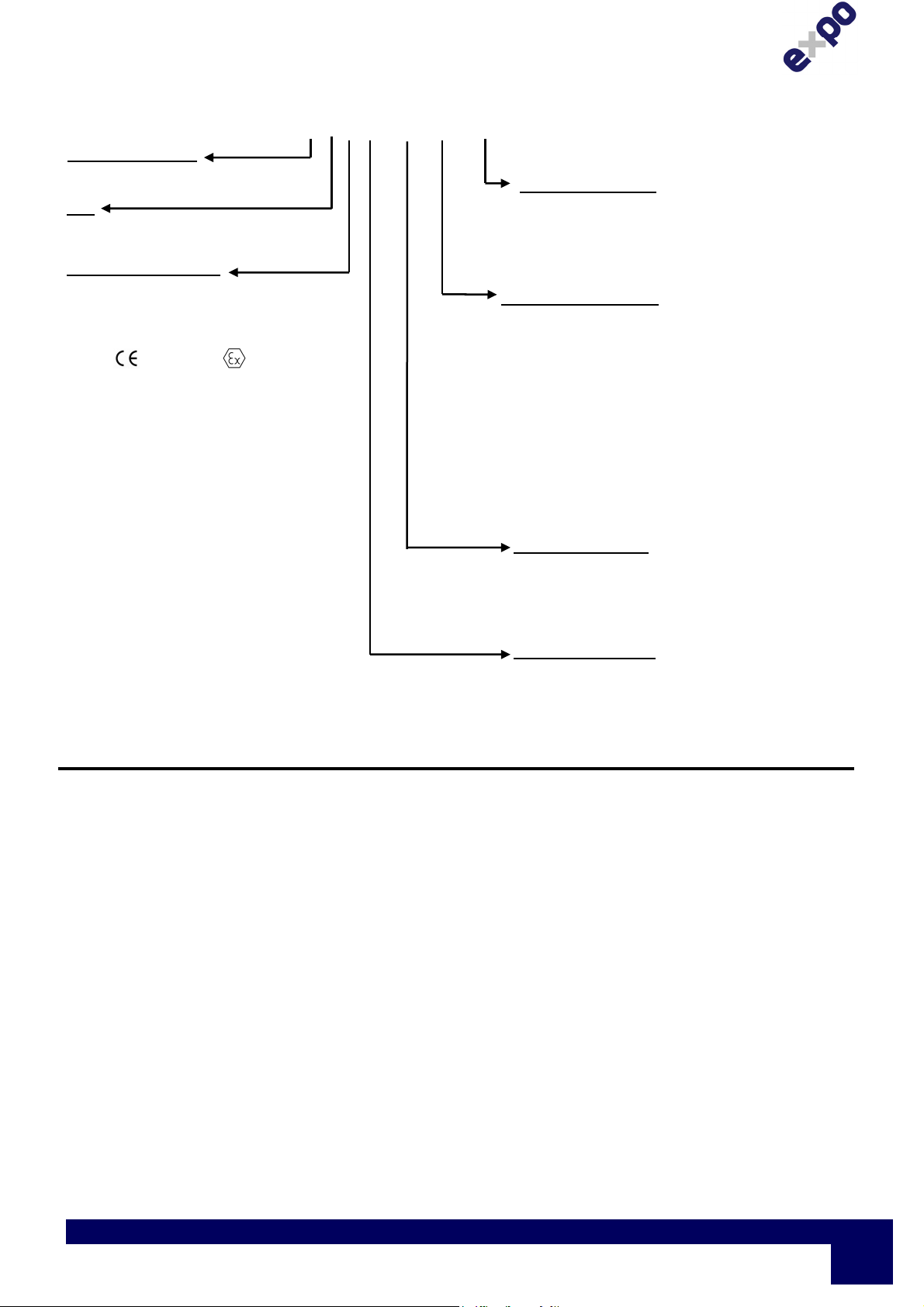
Model No. (Example): 07 1 XLC / ss / PO / WM (Note: Not all codes are applicable)
Purge System Type
07 = MiniPurge
Size
1 = Sub MiniPurge
Purge flow rate 225 Nl /min, 8 scfm
Approval / Certification
X =
Europe
EN60079-0, EN60079-2
Sira 01ATEX1295X
0518
Ex [pxb] IIC T6 Gb
Ex [pxb] IIIC T85ºC Db
Tamb -20ºC +55ºC
IEC
IEC60079-0, IEC60079-2
IECEx SIR 07.0027X
Ex [pxb] IIC T6 Gb
Ex [pxb] IIIC T85ºC Db
Tamb -20ºC +55ºC
BRAZIL
INMETRO- TÜV 12.1462X
Ex [pxb] IIC T6 Gb
Ex [pxb] IIIC T85ºC Db
Tamb -20ºC +55ºC
USA / Canada NFPA 496
FM 1X8A4AE
Class I Div 1 Groups A, B, C & D
UL E190061
Class I Div 1 Groups A, B, C & D
For limitations and conditions of use refer to the
applicable certificate at the back of this manual.
Supply Pressure: Must be regulated at inlet
Minimum 60 psi / 0.4 MPa / 4 bar
Maximum 115 psi / 0.8 MPa / 8 bar
Air Quality: Compressed air / Nitrogen to instrument quality
Ambient Temperature: -20ºC to + 55ºC
Leakage Compensation: Variable up to 2 scfm / 60 Nl/min to compensate for leakage of enclosure
Purge Timer: Stepped adjustable between 1 minute and 30 minutes
Flow & Pressure Sensors: CF: One sensor for both
“Low Pressure and Flow”: 1” WC / 250 Pa (2.5 mbar)
LC: “Low Pressure Sensor” 0.2” WC / 50 Pa (0.5 mbar)
“Flow Sensor” 1.13” WC/ 280 Pa / (2.8 mbar)
Relief Valve: System: CF LC
Model No: RLV25/ss RLV25/FS/ss
Opening Pressure: 4” WC / 1 kPa (10 mbar) 4” WC / 1 kPa (10 mbar)
Purge Flow Rate: N/A (see Spark Arrestor) 8 scfm / 225 Nl/min
Material: 316L Stainless Steel, Spark Arrestor: Stainless Steel mesh, Gasket: Neoprene
Spark Arrestor Unit Model No: SAU25
(CF systems only) Purge / Dilution Flow Rate: Between 0.4 & 8 scfm / 10 & 225 Nl/min (Default: 8 scfm)
7 user selectable orifice plates
Material: Stainless Steel
Bulkhead Pipe Fittings: Air Supply: 1/2” NPT
Output: 1/2” NPT
Signal: 1/8” NPT
II 2 (2) G D
Options as Required
AO = Alarm Only
MO = Manual Override
MK = MIU Mounting Kit (PO systems only)
WM = Wall Mounting Bars
Power & Alarm (Signals)
PO = Pneumatic Output
“Power” : On Purge Complete = 30 psi / 0.2 MPa / 2 bar Signal
“Alarm” : Loss of Pressure = No signal
”Pressurized” = 30 psi / 0.2 MPa / 2 bar Signal
PA = Power and Alarm Terminal Box Ex e IIC T5
Power and Alarm Terminal Box Ex e IIC T4
“Power” ; 250 Vac 4 Amp AC15 2PNO – Ex d IIC T6
“Alarm” : 250 Vac 4 Amp AC15 SPCO – Ex d IIC T6
(European and IEC Systems Only)
IS = Intrinsically Safe, Ex i & Ex i circuit
“Power” : used with others’ Ex i equipment
“Alarm” : Relay / Barrier
MiniPurge Housing
ss = 316L Stainless Steel
Neoprene “Top” Mount Gasket
pm = Panel Mount (Side/Front Mount) 316L
Stainless Steel
Presurization Method
CF = Continuous Flow
LC = Leakage Compensation
ML442 | v5k
Expo Technologies UK
T: +44 (0) 20 8398 8011
E: sales@expoworldwide.com
Expo Technologies US
T: +1 (440) 247 5314
E:sales.na@expoworldwide.com
Expo Technologies China
T: +86 532 8906 9858
E: qingdao@expoworldwide.com
Page
1

Visual Indicators: CF: Alarm / Pressurized (Red / Green)
Purge Complete (Red / Green)
LC: Alarm / Pressurized (Red / Green)
Purge Complete (Black / Amber)
Action on “Loss of Pressure”:
CF: Action on “Loss of Pressure” = “Alarm & Trip”. Option /AO specifies an “Alarm Only” kit.
LC: Action on “Loss of Pressure” = “Alarm & Trip” or “Alarm Only”. LC Model is user selectable.
Page
2
Expo Technologies UK
T: +44 (0) 20 8398 8011
E: sales@expoworldwide.com
Expo Technologies US
T: +1 (440) 247 5314
E:sales.na@expoworldwide.com
ML442 | v5k
Expo Technologies China
T: +86 532 8906 9858
E: qingdao@expoworldwide.com

2. Application Suitability
MiniPurge Systems are certified for use in Hazardous Areas, where the Hazardous Area is
non-mining (i.e. above ground) and the hazard is caused by flammable gasses, vapours or dust.
Depending on the model, the systems may be used in IECEx, ATEX Zone 1(21) - Category 2
and NEC 500 Class I, Div 1.
MiniPurge systems may be used for hazards of any gas group. However, apparatus
associated with the MiniPurge system, such as Intrinsically Safe signalling circuits and
flameproof enclosures containing switching devices may be limited in their gas group. The
certification documentation supplied with any such devices must be checked to ensure their
suitability.
This system is designed for use primarily with compressed air. Where other inert compressed
gasses are used (Nitrogen, for example) the user must take suitable precautions so that the
build-up of the inert gas does not present a hazard to health. Consult the Control of Substances
Hazardous to Health (COSHH) data sheet for the gas used. Where a risk of asphyxiation
exists, a warning label must be fitted to the Pressurized Enclosure.
The following materials are used in the construction of MiniPurge systems. If substances that
will adversely affect any of these materials are present in the surrounding environment, please
consult Expo for further guidance.
Materials of construction:
Stainless Steel Aluminium
Mild (carbon) Steel Nylon
Brass Polyurethane
Acrylic
Silicone Rubber
Neoprene
ML442 | v5k
Expo Technologies UK
T: +44 (0) 20 8398 8011
E: sales@expoworldwide.com
Expo Technologies US
T: +1 (440) 247 5314
E:sales.na@expoworldwide.com
Expo Technologies China
T: +86 532 8906 9858
E: qingdao@expoworldwide.com
Page
3
3. Description and Principle of Operation
All Expo Technologies MiniPurge pressurization systems provide:
a) a method of pressurizing a Pressurized Enclosure (PE) while at the same time compensating
for any leakage, together with
b) a method of purging the enclosure, before power is applied, to remove any flammable gas
that may have entered the enclosure while it was not pressurized,
c) visual indication of the MiniPurge system status, and
d) an output to provide remote indication or control.
The MiniPurge system comprises a number of component units. The units required depend on
the type of system selected. These are summarised in Table 1. The general description and
function of each is as follows:
3.1 Control Unit (CU)
The Control Unit (CU) is the heart of the system. It contains a pneumatic logic circuit specially
designed and built to control the functions required for purge and pressurization. For all systems
this includes air filtration, pressure and purge flow measurement, purge timing, and local visual
indication of Pressurized/Alarm and flow sensed. It also provides the outputs for power and
remote alarm control corresponding to the output type selected.
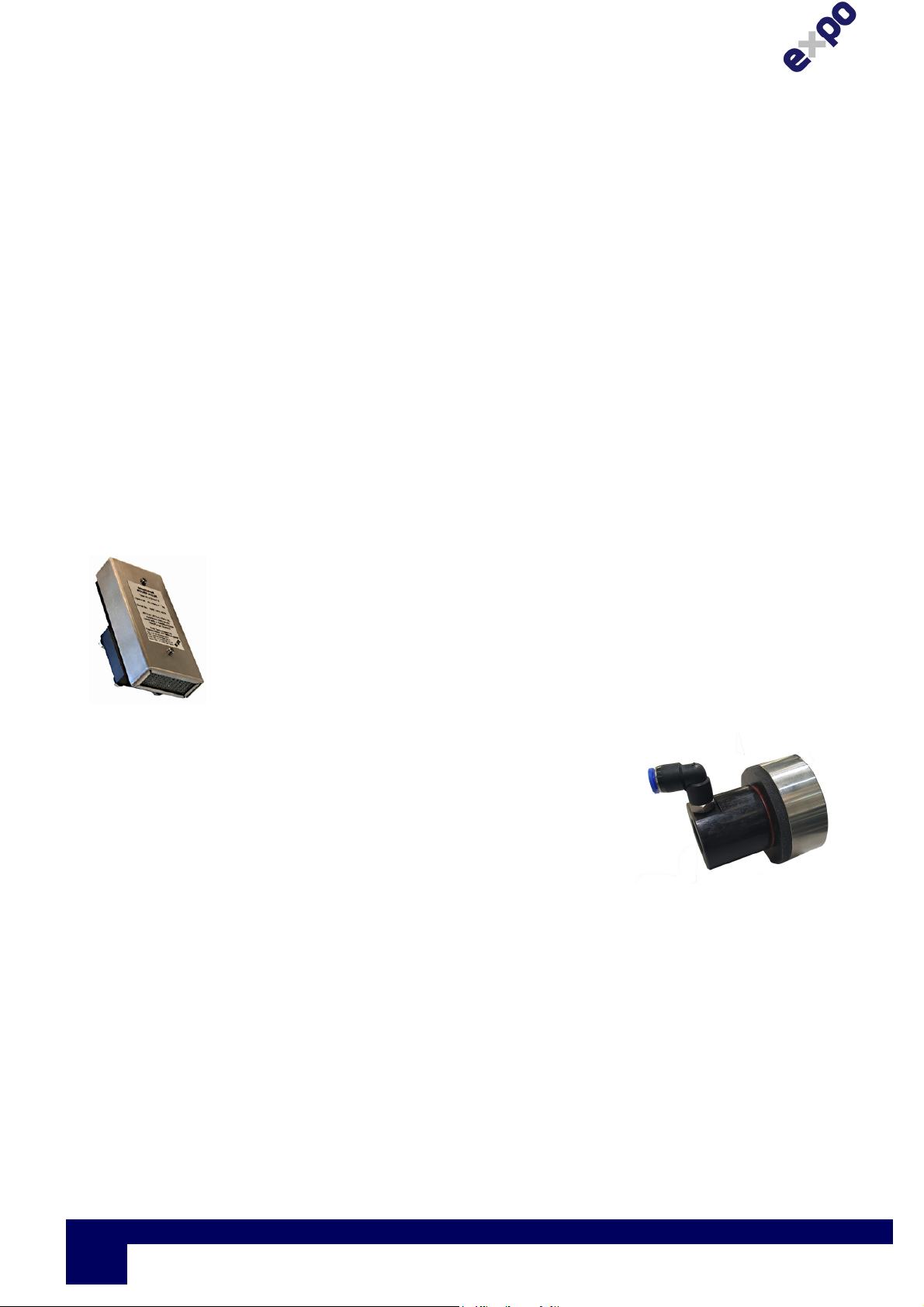
3.2 Relief Valve (RLV)
The Relief Valve unit is fitted to the PE to provide a means of limiting the
maximum pressure experienced by the PE during operation. The RLV
model number has a suffix giving the diameter of the valve aperture in
millimetres e.g. RLV25 (= 25mm bore). The RLV also incorporates a
Spark Arrestor to prevent sparks being ejected from the PE into the
classified area.
In Leakage Compensation systems, the RLV is combined with the flow
measurement mechanism.
Figure 1. LC Relief Valve
3.3 Calibrated Outlet Orifice/Spark Arrestor (SAU)
Continuous Flow systems incorporate the SAU25. This unit has a
range of interchangeable calibrated orifice plates, which are used
to measure the flow through the PE.
Figure 2 Spark Arrestor Type SAU25
3.4 The Methods of Pressurizing
a) CF - Continuous Flow
A Continuous Flow (CF) of protective gas is passed through the PE. Initially this flow is verified
and performs the purging phase of the operation. When the purging phase is completed – i.e.
the purge time has elapsed- the same flow of protective gas maintains the pressurization of the
enclosure. This flow may be required to dilute an internal source of hazardous gas release.
Page
4
Expo Technologies UK
T: +44 (0) 20 8398 8011
E: sales@expoworldwide.com
Expo Technologies US
T: +1 (440) 247 5314
E:sales.na@expoworldwide.com
ML442 | v5k
Expo Technologies China
T: +86 532 8906 9858
E: qingdao@expoworldwide.com
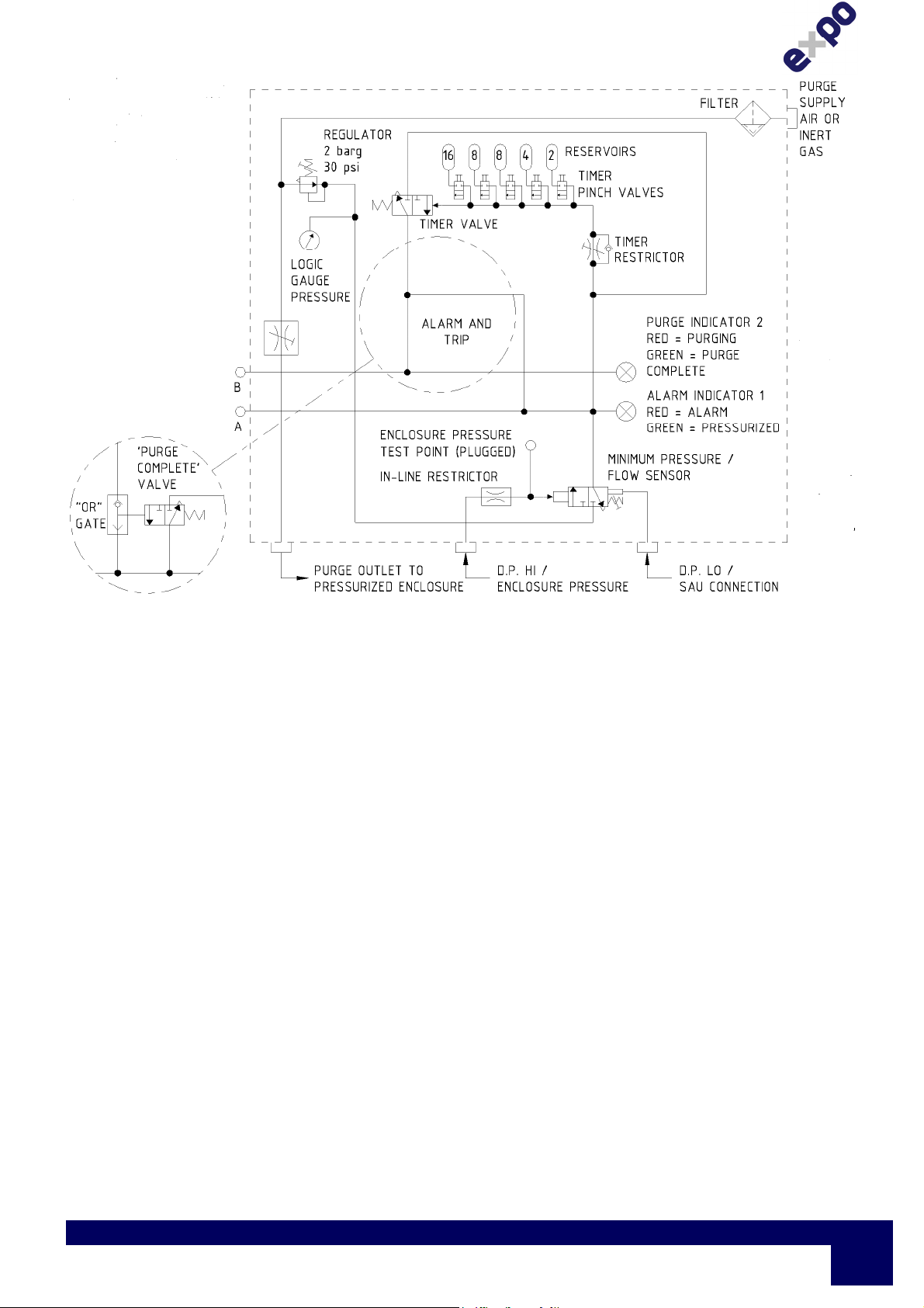
Figure 3 Continuous Flow Circuit Diagram
ML442 | v5k
Expo Technologies UK
T: +44 (0) 20 8398 8011
E: sales@expoworldwide.com
Expo Technologies US
T: +1 (440) 247 5314
E:sales.na@expoworldwide.com
Expo Technologies China
T: +86 532 8906 9858
E: qingdao@expoworldwide.com
Page
5
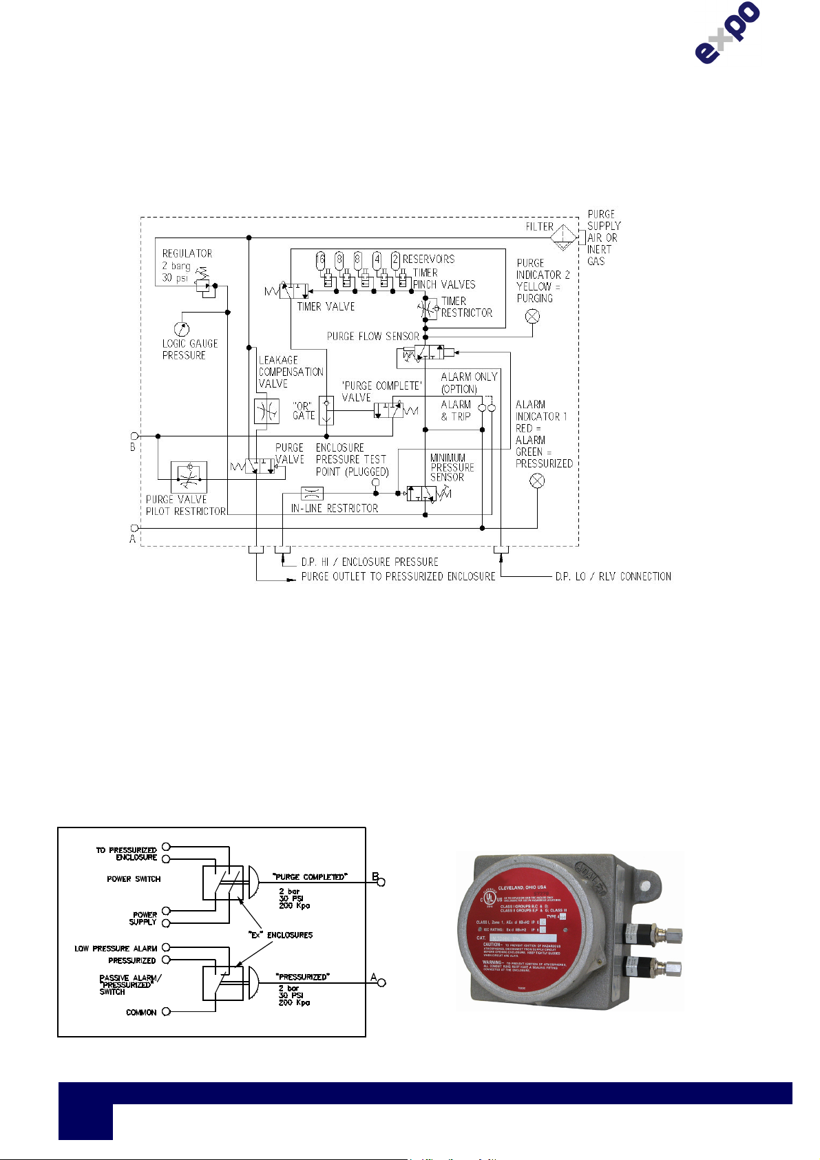
b) LC - Leakage Compensation
Initially a high flow of protective gas is passed through the enclosure. This flow is verified and
performs the purging phase of the operation. When the purging phase is completed – i.e. the
purge time has elapsed - the flow of protective gas is provided via an adjustable valve so that it
just compensates for any leakage from the PE in addition to maintaining its pressurization.
If leakage is less than 5 l/min then the LCV will be awkward to set. You will find that the RLV
spring will cycle open and closed. If this happens contact our service department for advice.
Figure 4 Leakage Compensation Circuit Diagram
3.5 Type of Output
The functions of the outputs are power control and alarm/pressurized indication. Power control
provides a signal to switch the power to the PE. Alarm output provides a passive signal to
indicate remotely when the enclosure is not pressurized and an active signal when pressurized.
a) PO- Pneumatic Output
The power control and pressurized outputs are pneumatic signals, which may be used to
operate other devices to provide power switching or alarm indication. The lack of any output
signal indicates incomplete purge and alarm. In many instances these outputs may be
connected to the Expo range of MiniPurge Interface Unit s (MIU).
Figure 5 Typical MiniPurge Interface Unit
type (MIU/dA)
Figure 6 Pneumatic Output Option
Page
6
Expo Technologies UK
T: +44 (0) 20 8398 8011
E: sales@expoworldwide.com
Expo Technologies US
T: +1 (440) 247 5314
E:sales.na@expoworldwide.com
ML442 | v5k
Expo Technologies China
T: +86 532 8906 9858
E: qingdao@expoworldwide.com
b) IS - Intrinsically Safe Output
The power control and alarm outputs are volt free contacts which form part of an Intrinsically
Safe (IS) circuit which then provides power control or alarm outputs in a safe (unclassified)
area. These contacts must only be connected to IS circuits as the switch contacts are in the
hazardous area. In many instances these outputs may be connected to the Expo range of
MiniPurge Interface Units (MIU).
Figure 7. Intrinsically Safe (IS) Option
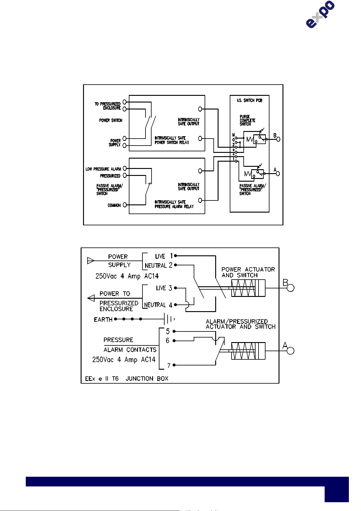
c) PA - Power and Alarm
Figure 8. Ex de Power and Alarm (PA) Option
The terminal box is Increased Safety (Ex e) certified and incorporates the terminal connection
points for the alarm and interlock circuits. All contacts provided are volt free (dry).
Cable entry methods (for example conduit or cable glands) must be certified to IECEx, ATEX or
INMETRO standards. The main requirement is that IP66 (or better) ingress protection must be
provided by use of seals or washers.
ML442 | v5k
Expo Technologies UK
T: +44 (0) 20 8398 8011
E: sales@expoworldwide.com
Expo Technologies US
T: +1 (440) 247 5314
E:sales.na@expoworldwide.com
Expo Technologies China
T: +86 532 8906 9858
E: qingdao@expoworldwide.com
Page
7

4. Installation of the System
This MiniPurge is designed for use under normal industrial conditions of ambient temperature,
humidity and vibration. Please consult Expo before installing this equipment in conditions that
may cause stresses beyond normal industrial conditions.
The MiniPurge system shall be installed in accordance with relevant standards, such as IEC /
EN 60079-14, NEC 500, NFPA 496 and any local codes of practice that are in force.
There are up to three components for the MiniPurge system, dependent upon the system type:
System type Control Unit (CU)
Relief Valve
(RLV)
Leakage Compensation YES YES Integral to RLV
Continuous Flow YES YES YES (SAU25)
Table 1 System Components
4.1 Control Unit (CU)
The MiniPurge system should be installed either directly on or close to the PE. See mounting
details. Generally the most convenient arrangement is to install the CU on the top of the PE.
Must be mounted vertically as shown in MiniPurge Configuration XBR-7TD0-003. The CU can
be mounted on the side of the PE using the rear mounting fixings. The piped connections to the
PE should be made using metallic tube through suitable bulkhead connections. The CU can be
remote mounted using the wall mounting bars (/WM option), and should be installed as close as
possible to the PE. It should be installed so that the system indicators and certification labels
may be readily observed.
4.2 Relief Valve (RLV) and Spark Arrestor Unit (SAU)
To achieve efficient purging the points where air enters and exits the PE should normally be at
opposite ends of the PE. These items must be mounted vertically. The RLV or SAU are
recommended to be situated at the bottom, or on the side of the enclosure at the bottom, when
the CU is top mounted on the enclosure, thus achieving top to bottom purging. The purge air
may be piped within the PE to ensure purging of potential dead air spots.
It is important that the interior and exterior of the Spark Arrestor is kept clean and debris is not
allowed to accumulate which might affect the calibration of the device. In particular the exterior
of the Spark Arrestor should not be painted or blocked off in any way.
4.3 Connections to Protective Gas Supply
The MiniPurge® system should be connected to a protective gas supply, which is suitable for
purging and pressurization.
The supply pipe connection to the MiniPurge® must be appropriate for the maximum input flow
rate for the application.
The air supply must be regulated at a pressure less than the maximum stated inlet pressure.
The air supply must be: clean, non-flammable and from a non-hazardous location. The air
should be of Instrument Air Quality. Although the purge control system will operate with lower
air quality, its operational life will be adversely affected. The equipment that is being protected
by the MiniPurge® may also suffer because of poor air quality.
With reference to BS ISO 8573-1: 2010, Instrument Air is typically specified as:
Spark Arrestor
Unit
Page
8
Expo Technologies UK
T: +44 (0) 20 8398 8011
E: sales@expoworldwide.com
Expo Technologies US
T: +1 (440) 247 5314
E:sales.na@expoworldwide.com
ML442 | v5k
Expo Technologies China
T: +86 532 8906 9858
E: qingdao@expoworldwide.com

Particle Class 1
In each cubic metre of compressed air, the particulate count should not exceed 20,000 particles
in the 0.1 to 0.5 micron size range, 400 particles in the 0.5 to 1 micron size range and 10
particles in the 1 to 5 micron size range.
Humidity or pressure dew point
The dew point, at line pressure, shall be at least 10 °C below the minimum local recorded
ambient temperature at the plant site. In no case, should the dew point at line pressure exceed
+3 °C.
Oil Class 2
In each cubic metre of compressed air, not more than 0.1mg of oil is allowed. This is a total
level for liquid oil, oil aerosol and oil vapour.
When an inert gas is being used to supply the purge system, risk of asphyxiation exists. Refer
to Application Suitability section.
Before connection of the air supply to the purge system, the supply pipe work should be flushed
through with instrument quality air to remove any debris that may remain in the pipes. This must
be carried out for at least 10 seconds for every meter of supply pipe.
Unless a supply shut-off valve has been fitted to the MiniPurge® system, an external shut-off
valve with the same, or larger, thread size as the Control Unit inlet fitting should be fitted by the
installer to prevent any restriction of purge flow.
The purge air from the MiniPurge® Control Unit should be piped within the pressurized
enclosure to ensure purging of potential dead air spots.
The purge system is fitted with an internal regulator factory set to 3 bar feeding the logic.
4.4 Purge Air from CU to PE
When the CU is directly top mounted onto the PE, no connection will normally be necessary, as
the purge air will discharge into the PE directly. When the CU is not top mounted, or where
internal air distribution is necessary a connection should be made from the purge air outlet on
the CU (normally ½” NPT Female), via pipe pressure rated at least to the supply pressure, to
the PE. This should be kept as short as possible and should be adequately sized to ensure that
the full purge flow can be delivered.
4.5 CU to Enclosure Pressure Monitor
When the CU is mounted directly on the top of the PE, no connection will normally be
necessary, as the enclosure pressure monitor point will sense directly inside the PE.
If the CU is not mounted directly on the top of the PE or if there are fans, which may create
localised low-pressure areas within the PE, it is necessary to pipe this connection. The
connection is made to the enclosure pressure sensor fitting (normally 1/8” NPT Female) on the
CU. There is virtually no flow in this circuit, so small bore tube may be used. Expo
recommends 6mm O/D metal tube. Make sure that all connections are free of leaks.
4.6 CU to Flow Sensor
In Continuous Flow (CF) systems, a Differential Pressure Sensor is combined with the Minimum
Pressure Sensor and measures the "DP HI (High) / Enclosure Pressure" within the PE and the
pressure in the monitoring device at the back of the SAU "DP LO (Low) SAU Connection". This
connection requires a pipe connection between the CU and the SAU25.
ML442 | v5k
Expo Technologies UK
T: +44 (0) 20 8398 8011
E: sales@expoworldwide.com
Expo Technologies US
T: +1 (440) 247 5314
E:sales.na@expoworldwide.com
Expo Technologies China
T: +86 532 8906 9858
E: qingdao@expoworldwide.com
Page
9
In Leakage Compensation (LC) systems a dedicated Purge Flow Sensor measures the
differential pressure between the "DP HI (High) / Enclosure Pressure" and the pressure in the
monitoring device at the back of the RLV "DP LO (Low) RLV Connection". This connection
requires a pipe to connect the CU to the RLV25.
4.7 Power Supplies and their Isolation
All power entering the PE shall be provided with a means of isolation. This requirement also
applies to any external power sources, which are connected to equipment such as "volt-free" or
"dry" contacts within the PE. Printer signal, network cards, etc need isolation.
Exception: Power to other apparatus that is already suitable for the hazardous area need not to
be isolated by the MiniPurge system.
In all cases the application and the isolation of the power must be controlled by the MiniPurge
system. Refer to Specification Sheet for output options available.
4.8 Adjustments and Settings
Purge Time
If no specific purge test has been performed on the PE, the volume of the PE must be
determined by the manufacturer or user and the necessary purging time calculated based on
the purge flow rate specified by the “standard” being used. It is the user's responsibility to verify
or enter this data on the PE and/or MiniPurge system nameplate. Ask Expo if in doubt. The
IEC / EN 60079-2 permits 5 free volume changes and an example of the calculations is as
follows:
If the PE external dimensions indicate an internal free volume of 500 Litres then,
500 litres enclosure volume x 5 volume changes = 12 minutes purge time
225 litres/minute purge flow rate
If the PE is a motor, experience of purge testing shows that it is prudent to multiply the
motor internal "free” volume by ten to get the purging volume.
500 litres enclosure volume x 10 volume changes = 23 minutes purge time
225 litres/minute purge flow rate
The following applies for NFPA 496 standards where 4 complete volume changes are permitted
for enclosures except when the PE contains a motor when 10 volume changes are required.
If the PE external dimensions indicate a total volume of 8 cubic foot, then,
8 cubic foot enclosure volume x 4 volume changes = 4 minutes purge time
8 cubic foot/minute purge flow rate, (see above)
If the same PE contains a motor, then,
8 cubic foot enclosure volume x 10 volume changes = 10 minutes purge time
8 cubic foot/minute purge flow rate, (see above)
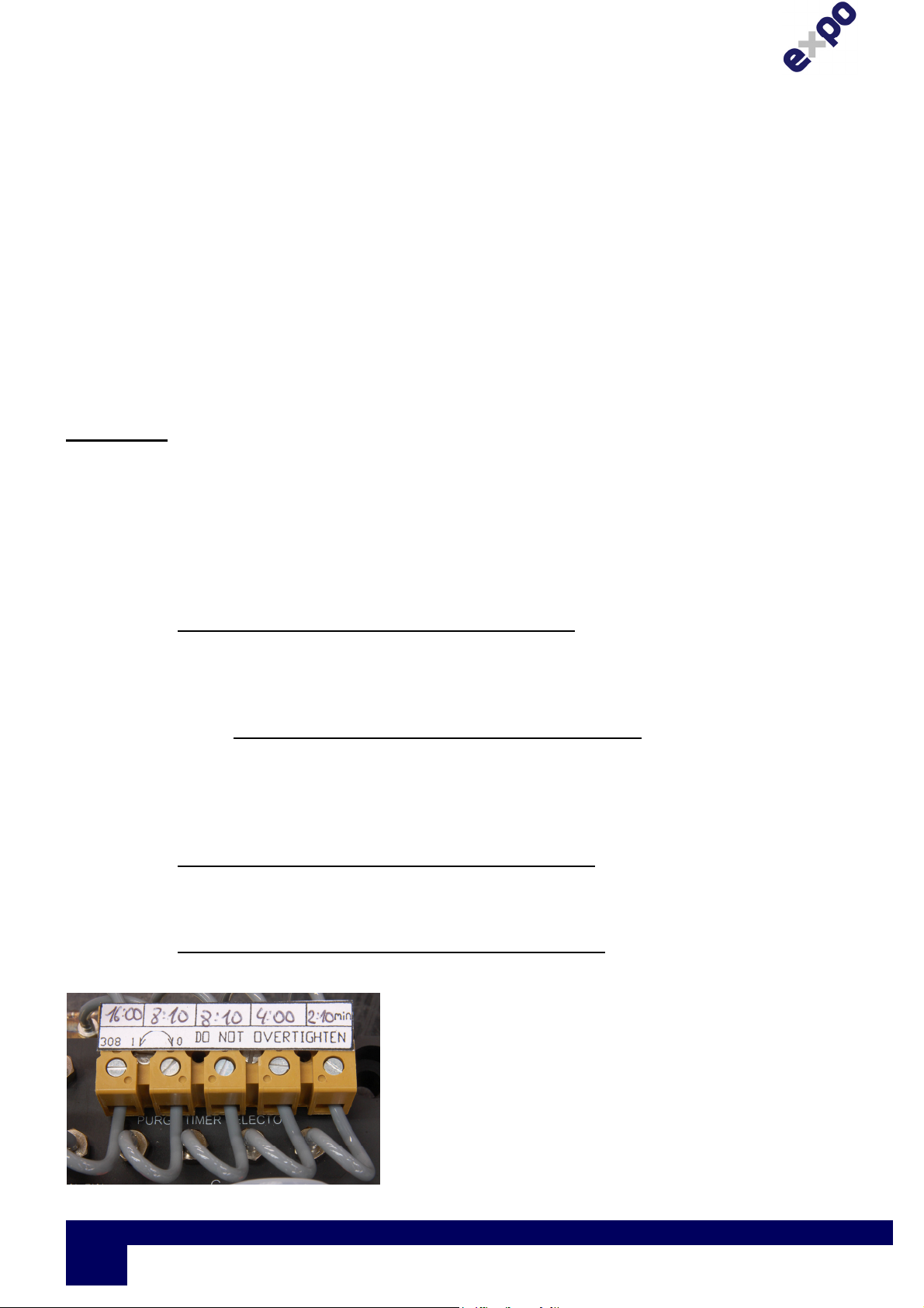
The standard MiniPurge units have the patented digital
pneumatic timer system as shown in Figure 9
MiniPurge timer block. The purge time is set by
opening / closing the pinch valve so that the sum of the
open valve times equals or exceeds the required purge
time. At least one valve must always be open, and
the screws must be at the appropriate limit of travel.
Do not over tighten.
Figure 9 MiniPurge timer block
Page
10
Expo Technologies UK
T: +44 (0) 20 8398 8011
E: sales@expoworldwide.com
Expo Technologies US
T: +1 (440) 247 5314
E:sales.na@expoworldwide.com
ML442 | v5k
Expo Technologies China
T: +86 532 8906 9858
E: qingdao@expoworldwide.com
 Loading...