

Page 1
PMC-Eight™
Programmer’s
Reference
DOC-ESPMC8-002 Release 2
2019_March 07
Page 2

Explore Scientific PMC-Eight™ Controller Programmer’s Reference
DOC-ESPMC8-002 Rev. 1.2 2019 March 07 (Firmware 09T10, 10A01 and above)
Copyright ©2016-2019 Explore Scientific, LLC. ExploreScientificUSA.com +1 (866) 252-3811, 1010 South 48th Street, Springdale, AR 72762
1
Revised by: Jerry Hubbell, Vice President Engineering, Explore Scientific, LLC.
Reviewed by: Alex Sanchez, Director Quality Explore Scientific, LLC.
Reviewed by: Dan Dickerson, APh Technological Consulting
Approved by: Scott Roberts, President Explore Scientific, LLC.
This document is copyright ©2016–2019 Explore Scientific, LLC. All Rights Reserved.
NOTE: This document is provided to our PMC-Eight™ customers for their personal use in developing
applications for the PMC-Eight™ Control System in accordance with the requirements of Explore Scientific
and the PMC-Eight™ OpenGOTO™ Community Steering Committee.
If you have any comments or questions about this document, please contact:
Attn: Vice President of Electrical Engineering
Explore Scientific, LLC
1010 South 48th Street
Springdale, AR 72762
(866) 252-3811
The PMC-Eight™ and OpenGOTO™ Name and Logo are registered trademarks of Explore Scientific, LLC,
All Rights Reserved. The JingHua Optical Corporation (JOC) located in Guangzhou, China is the parent
company of Explore Scientific.
Propeller™ copyright Parallax, Inc. SBIG ST-4 standard copyright Santa Barbara Instruments Group,
Cyanogen, LLC. RN-131 module copyright Microchip, Inc. ESP-WROOM-02 (ESP8266) module copyright
Espressif, LLC. G-11 mount copyright Losmandy Astronomical Products, Hollywood General Machining,
Inc. PHD2 copyright Open PHD Guiding Project.
This is the third in the following series of documents for the PMC-Eight™ System:
Document Number Title
DOC-ESPMC8-001A PMC-Eight™ Owner’s Reference Manual (Customer Use)
DOC-ESPMC8-001B iEXOS 100 PMC-Eight™ Owner’s Reference Manual (Customer Use)
DOC-ESPMC8-002 PMC-Eight™ Programmer’s Reference (Customer Use)
DOC-ESPMC8-003 PMC-Eight™ JOC Command Language Reference (Internal Use)
DOC-ESPMC8-004 PMC-Eight™ Datasheet and Design Basis Document (Internal Use)
DOC-ESPMC8-005 PMC-Eight™ Firmware and Software Design Reference (Internal Use)
DOC-ESPMC8-006 PMC-Eight™ Firmware and Software Flowcharts (Internal Use Only)
DOC-ESPMC8-007 PMC-Eight™ Hardware Reference Schematics and Datasheets (Internal Use)
Page 3

Explore Scientific PMC-Eight™ Controller Programmer’s Reference
DOC-ESPMC8-002 Rev. 1.2 2019 March 07 (Firmware 09T10, 10A01 and above)
Copyright ©2016-2019 Explore Scientific, LLC. ExploreScientificUSA.com +1 (866) 252-3811, 1010 South 48th Street, Springdale, AR 72762
2
Document Notes
Revision History
0.0 GRH DRAFT Initial Draft.
0.1 GRH DRAFT Added Sections VI and VII.
0.2 GRH DRAFT Revised Section V to add “ESR!” Communications Reset command.
0.3 GRH DRAFT Revised Section III to correct and expand on Meridian Flip discussion.
1.0 GRH RELEASE 0 Miscellaneous cleanup of text and sections for release.
1.1 GRH RELEASE 1 Revised Section II to add board layout information and LED and test point
information. Miscellaneous revisions and formatting changes.
1.2 GRH RELEASE 2 Revised Sections II–VIII to add information about the iEXOS 100 mount and
other updates. Added Appendix section for miscellaneous information, including
Application Notes. Miscellaneous cleanup of text.
This document uses the following convention for units of measure. Instead of stating: 30 counts/second
or 20 arc-sec/count, or 20 arc-sec per count, the units are stated as: 30 counts sec-1 or 20”arc count-1. The
superscript -1 indicates that the unit is in the denominator. You will see , ‘, and “ for degrees, minutes,
and seconds for angular values.
Motor count values are stated in decimal (115200) and hexadecimal (0x9C40) notation. The terms counts
and microsteps are synonymous depending on the usage. All the values returned by the controller are
hexadecimal strings such as “1F92CA”. Actual commands are shown in Courier New font with quotes
around the command string, i.e., “ESGp0!”. Do not include the quotes when typing the commands at a
terminal connected to the controller. Program names used to communicate with the PMC-Eight™ are
designated in Bold Italic, i.e., Parallax Serial Terminal.
The PMC-Eight™ Control System is warranted by Explore Scientific, LLC. If you have any questions or
issues when using this reference with your PMC-Eight™ system, you should contact Explore Scientific
Customer Support at +1 (866) 252-3811
CAUTION: BOARD FAILURE INDUCED THROUGH PROBING THE CIRCUITRY IS NOT COVERED UNDER THE
PMC-Eight™ LIMITED WARRANTY.
Page 4

Explore Scientific PMC-Eight™ Controller Programmer’s Reference
DOC-ESPMC8-002 Rev. 1.2 2019 March 07 (Firmware 09T10, 10A01 and above)
Copyright ©2016-2019 Explore Scientific, LLC. ExploreScientificUSA.com +1 (866) 252-3811, 1010 South 48th Street, Springdale, AR 72762
3
Table of Contents
Document Notes 2
Table of Contents 3
Glossary 3
Acronyms 4
I. Introduction 5
II. System Description 6
III. PMC-Eight™ Controller and Command Language
Theory of Operation 13
IV. PMC-Eight™ ASCII Command Language 20
V. PMC-Eight™ ASCII Command Language Syntax 22
VI. PMC-Eight™ Hardware Interface Specifications 32
VII. PMC-Eight™ System Software Development Kit Information 33
VIII. Miscellaneous System Information 34
IX. Appendices 35
Application Note AN001: Firmware Update Procedure 36
Application Note AN002: Model 2A Switching Communications 39
Application Note AN003: Model 1A Switching Communications 44
Model 2A Analog Autoguider (ST4) Port Calibration Procedure 50
ASCOM Platform Conformance Test – PMC-Eight™ ASCOM Driver 55
Glossary
Axis—The rotational axis that the motor is driving, either RA or DEC.
Right Ascension (RA)—The rotational axis that parallels the Earth’s rotational axis.
Declination (DEC)—The rotational axis that allows the scope to move north or south.
German Equatorial Mount (GEM)—A type of mount that positions the telescope to move on one axis to
counteract the rotation of the Earth.
Hexadecimal—The base 16 number system using characters “0” through “9” and “A” through “F”.
Decimal—The normal base 10 number system used in everyday life using characters “0” through “9”.
Rate—The rotational speed at which the motors are driving the mount.
Position—The number of microsteps the motor has moved since startup.
Direction—The direction of the motor rotation (clockwise, or counterclockwise) when looking at the
shaft end.
Tracking Rate—The precision rotational speed of the RA axis motor at a very slow rate. Used to
counteract the rotation of the Earth.
Tracking—The act of counteracting the rotation of the Earth to keep an object in the center of the
telescope field-of-view (FOV).
North Celestial Pole (NCP)—The point in the Celestial Sphere where the Earth’s rotational axis points in
the Northern Hemisphere. Likewise, with the South Celestial Pole (SCP) in the Southern Hemisphere.
Firmware—The computer instructions installed in the permanent memory of the processor that
communicate directly with the hardware I/O on the system. The firmware is compiled on an external
computer and uploaded via the serial RS232(DB9)/USB communications port.
RS232—A communications hardware standard for serial communications.
Page 5

Explore Scientific PMC-Eight™ Controller Programmer’s Reference
DOC-ESPMC8-002 Rev. 1.2 2019 March 07 (Firmware 09T10, 10A01 and above)
Copyright ©2016-2019 Explore Scientific, LLC. ExploreScientificUSA.com +1 (866) 252-3811, 1010 South 48th Street, Springdale, AR 72762
4
Acronyms
DEC Declination
EpW East Pointing West
FOV Field-of-View
GEM German Equatorial Mount
HA Hour Angle
HMI Human-Machine Interface
I/O Input/Output
JOC Jinghua Optical Corporation
LDO Low Drop Out
LMST Local Mean Sidereal Time
NCP/SCP North Celestial Pole/South Celestial Pole
OTA Optical Tube Assembly
PMC Precision Motion Controller
PMGR Programmer
RA Right Ascension
TCP Transmission Control Protocol
UDP User Datagram Protocol
WpE West Pointing East
Page 6

Explore Scientific PMC-Eight™ Controller Programmer’s Reference
DOC-ESPMC8-002 Rev. 1.2 2019 March 07 (Firmware 09T10, 10A01 and above)
Copyright ©2016-2019 Explore Scientific, LLC. ExploreScientificUSA.com +1 (866) 252-3811, 1010 South 48th Street, Springdale, AR 72762
5
I Introduction
The Explore Scientific PMC-Eight™ Controller Programmer’s Reference contains the information needed
to understand the controller operation and to communicate and use the base controller command
language. This document contains the system description and other data that can be used to create
programs to control the PMC-Eight™. More information about the PMC-Eight™ controller can be found
on the Explore Scientific website at ExploreScientificUSA.com. Additional information is included in the
Application Notes available on the PMC-Eight™ webpage and in Section VIII: Appendices of this document.
One of the key elements of the PMC-Eight™ System is the Explore Scientific PMC-Eight™ Command
Language. This language is designed to be both flexible and powerful enough to instruct the controller to
perform any task the controller can perform. This language is different from most mount controller
languages in that it does not contain astronomy or telescope mount specific commands. This language
contains more generic motion control commands that enable the user to quickly learn and use the system.
The PMC-Eight™ System also has a built-in JOC Command Interpreter used by the OpenGOTO™ Explore
Stars App available at the Microsoft App Store, Google Play Store, and Apple App Store.
The PMC-Eight™ architecture was driven by the design philosophy of abstracting the astronomical
functions from the hardware/firmware layer and encapsulating them within the software
driver/application layer. This provides several benefits to the overall performance, reliability, and
operation of the control system. The system architecture is very similar to other industrial motion control
systems that are used for single and multiple motor control functions used in robotics, power plants, and
manufacturing facilities.
The model 2A circuit board design includes several features that contribute to the reliability and thermal
performance of the control system, including:
• Simple three-layer circuit assembly design with an internal ground-plane used as the system
electrical common and as a thermal heat sync. This design helps evenly distribute the heat from
the components throughout the board and out through the DB9 connectors and the all-aluminum
enclosure. The on-board LDO voltage regulators also provide a source of heat when operating in
very cold temperatures < 5F (< -15C).
• Electronic components are widely distributed on a single side of the circuit assembly to minimize
the chance of defects arising during manufacturing that could occur when placing components on
both top and bottom layers of the circuit board. This also contributes to the even distribution of
heat throughout the circuit board assembly.
• Wide circuit traces are used to maximize the conductivity between component pins and minimize
the voltage drop between components. This considerably reduces the amount of heat generated
when power from the on-board voltage regulators is delivered to the high-current motor driver
and motors. This greatly contributes to the long expected lifetime of the Model 2A.
• A conformal coating is applied to both sides of the completed circuit board assembly to create a
moisture barrier that protects the components from degradation due to moisture when operating
in high-humidity environments coupled with large temperature changes.
Most of these features are not included in the PMC-Eight™ Model 1A used in the iEXOS 100 mount.
Page 7
Explore Scientific PMC-Eight™ Controller Programmer’s Reference
DOC-ESPMC8-002 Rev. 1.2 2019 March 07 (Firmware 09T10, 10A01 and above)
Copyright ©2016-2019 Explore Scientific, LLC. ExploreScientificUSA.com +1 (866) 252-3811, 1010 South 48th Street, Springdale, AR 72762
6
II System Description
The PMC-Eight™ is a high-precision stepper motor controller that very accurately controls the pointing
and tracking of a telescope mount. The design basis for this “industrial strength” Precision Motion
Controller (PMC) includes features to increase the reliability and flexibility of the system. The PMC-Eight™
model 2A includes several electrical and thermal design features and characteristics that provide plenty
of margin to ensure a long product lifetime in terms of individual assembly performance in the field, and
in the life-cycle of the design. The model 1A includes a basic level of thermal design features that help to
distribute and dissipate the heat generated in the system. Additional design elements incorporated in the
model 1A and 2A firmware take full advantage of the deterministic processing inherent in the processor
architecture to prevent complete system lockups. The system is designed to fail gracefully. While
individual functions of the system may fail due to external factors, the whole system should not
experience the lockups that other interrupt driven system may experience.
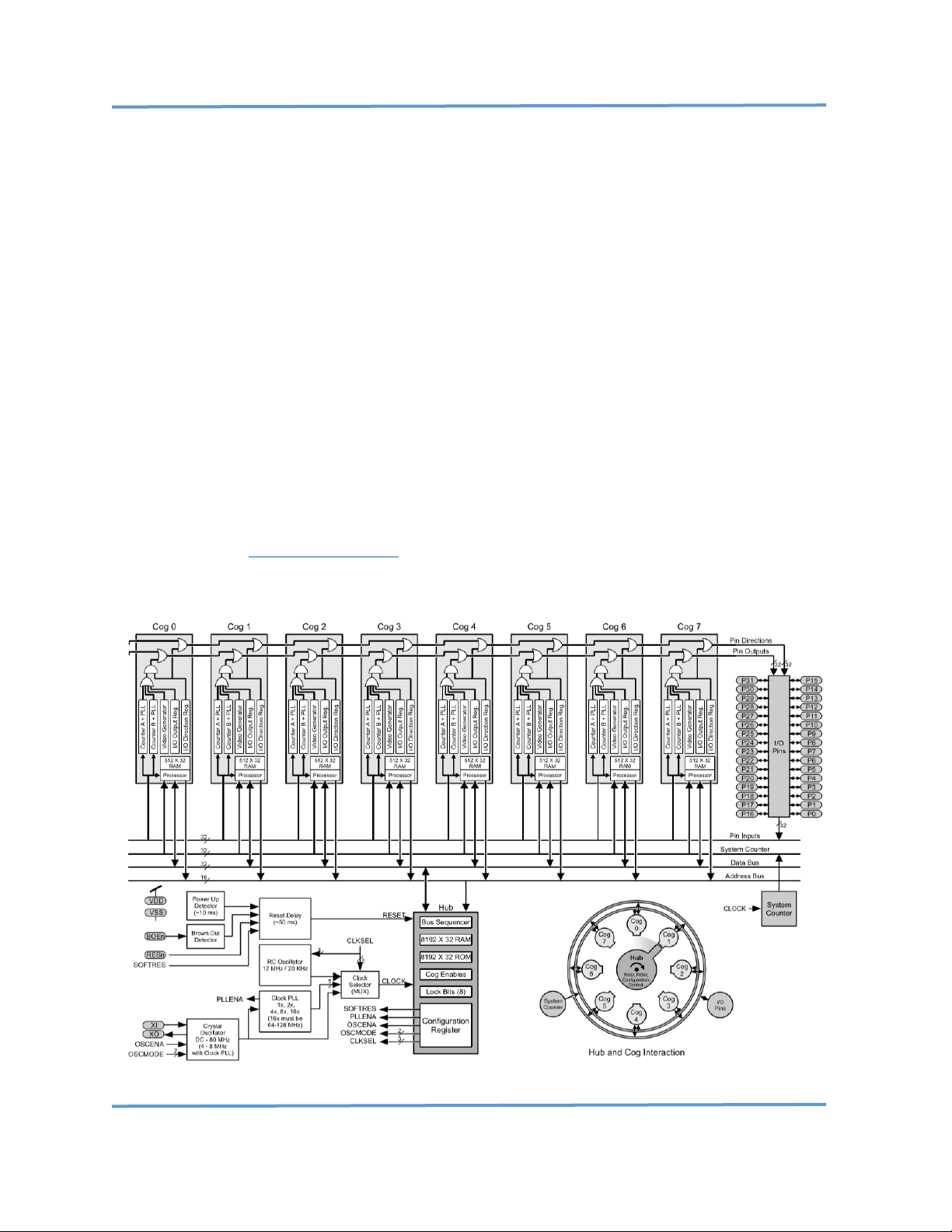
The microcontroller selected is a unique multi-processor design that uses eight processors, all working as
independent units and communicating through shared global memory. Each of these processors is
deterministic in its operation and DOES NOT use interrupts. This ensures that the task assigned to each
processor runs independently, and any failure of any one task does not cause a cascading failure in any of
the other processors; the result is a system that is designed to keep running even with a partial shutdown
of the processor. For more information about the operation of the Parallax Propeller™ Microprocessor
Chip, download the Propeller™ Datasheet . Note that both the model 2A and 1A use the same components
and have nearly identical schematics.
Parallax Propeller™ P8X32A 8-Processor Architecture/Block Diagram
Page 8
Explore Scientific PMC-Eight™ Controller Programmer’s Reference
DOC-ESPMC8-002 Rev. 1.2 2019 March 07 (Firmware 09T10, 10A01 and above)
Copyright ©2016-2019 Explore Scientific, LLC. ExploreScientificUSA.com +1 (866) 252-3811, 1010 South 48th Street, Springdale, AR 72762
7
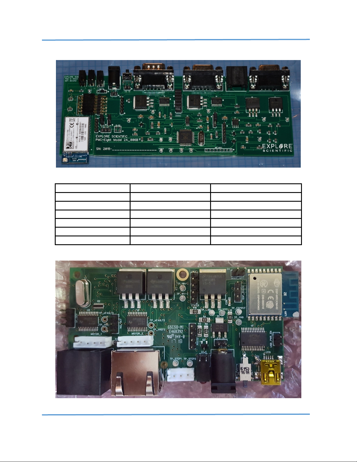
Both the PMC-Eight™ model 2A and 1A use the same components and have nearly identical schematics.
PMC-Eight™ Controller Model 2A-06B
Component
Part Number
Description
1(ea) Microcontroller
Parallax P8X32A-Q44
Propeller 8-CPU Microcontroller
1(ea) 8x64k Memory
Microchip AT24C512C
EEPROM Firmware & Storage
2(ea) Motor Driver
Texas Instruments DRV8835
Stepper Motor Driver Chip
1(ea) 2A-06B WiFi Module
Microchip RN-131G
WiFi Module
1(ea) 1A-01C WiFi Module
Espressif ESP8266
ESP-WROOM-02 WiFi Module
1(ea) 1A-01C USB
FTDI FT232RL
USB Serial Interface Chip
PMC-Eight™ Major Component List
PMC-Eight™ Controller Model 1A TOP
Page 9
Explore Scientific PMC-Eight™ Controller Programmer’s Reference
DOC-ESPMC8-002 Rev. 1.2 2019 March 07 (Firmware 09T10, 10A01 and above)
Copyright ©2016-2019 Explore Scientific, LLC. ExploreScientificUSA.com +1 (866) 252-3811, 1010 South 48th Street, Springdale, AR 72762
8
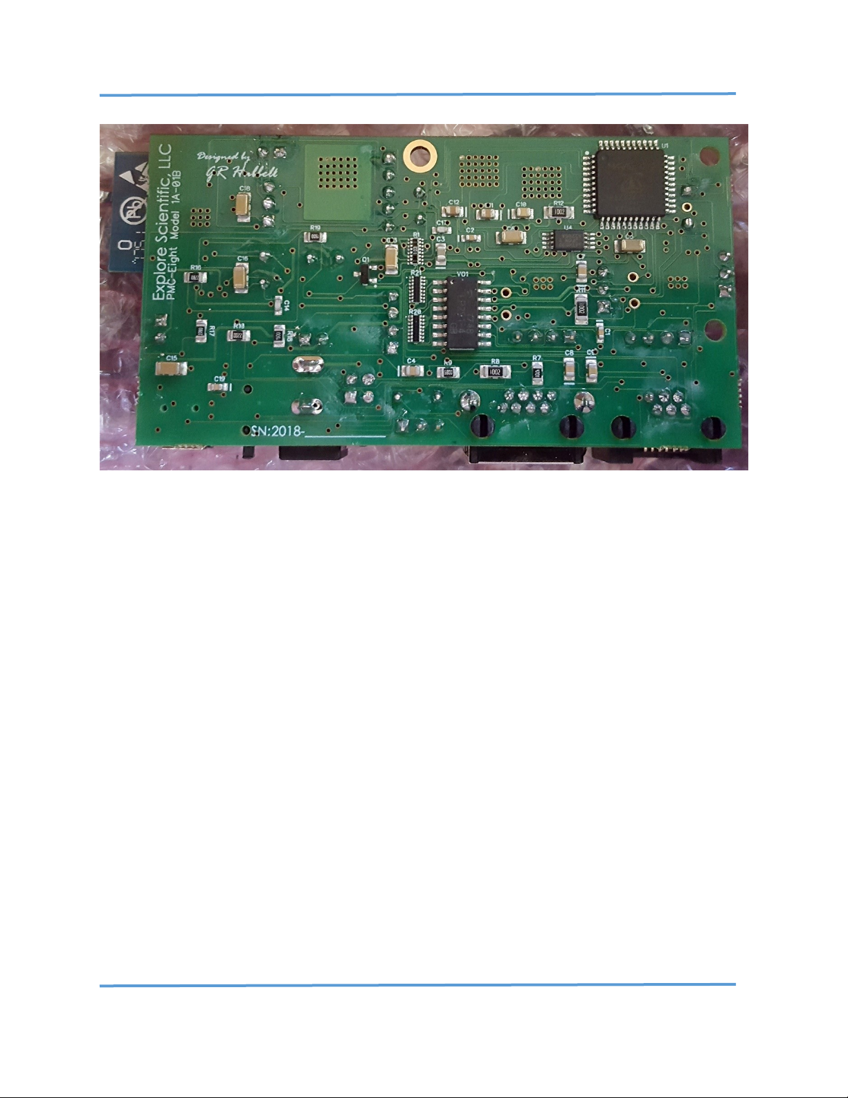
PMC-Eight™ Controller Model 1A BOTTOM
The PMC-Eight™ system consists of several components and is designed to interface with the Host
Computer in several different ways. The primary interface to the PMC-Eight™ Model 2A-06B is through a
dedicated RS-232 interface (DB-9 connector) that serves both as the programmer’s (PGMR) interface for
loading updated firmware into the system and as the interface for sending data request commands and
receiving data. The primary interface to the PMC-Eight™ Model 1A-01C is through a dedicated mini-USB
type B connector that serves both as the programmer’s (PGMR) interface for loading updated firmware
into the system and as the interface for sending data request commands and receiving data. A wireless
network interface (Wi-Fi) is available also for sending data request commands and receiving data. This
wireless interface is the primary HMI interface for the OpenGOTO™ Explore Stars application available for
the Microsoft Windows OS, Google Android OS, and Apple iOS. For details, see Section VII, Miscellaneous
Programming Application Notes. The controller communicates at 115,200 BAUD with No Parity, 8 Bits, 1
Stop Bit over the network, through the RS232 connection and the USB connection.
Page 10

Explore Scientific PMC-Eight™ Controller Programmer’s Reference
DOC-ESPMC8-002 Rev. 1.2 2019 March 07 (Firmware 09T10, 10A01 and above)
Copyright ©2016-2019 Explore Scientific, LLC. ExploreScientificUSA.com +1 (866) 252-3811, 1010 South 48th Street, Springdale, AR 72762
9
PMC-Eight™ System Boot Up
When the PMC-Eight™ system boots up, if you are connected to it via the wired PGMR/Serial port, you
will see the following displayed on the Parallax Serial Terminal:
-------------------------------------------------------------
------------------------------------------------------------ PPPPPPP MM MM CCCCCCCC 88888
PP PP MMM MMM CC 88 88
PPPPPPP MM M M MM CC XXXXX 888
PP MM M M MM CC 88 88
PP MM MM MM CCCCCCCC 88888
------------------------------------------------------------Copyright 2013-2018 Explore Scientific LLC., Gerald R Hubbell
1010 South 48th Street, Springdale, AR 72762
PMC-Eight Support 1-866-252-3811
http://www.explorescientificusa.com
------------------------------------------------------------Portions of FIRMWARE covered by MIT LICENSE terms
------------------------------------------------------------Explore Scientific PMC-Eight Controller - Startup
Initializing PMC-Eight Model 1A-01C-FW10B1a 10 AUGUST 2018...
CONFORM TEST VERSION - COMMUNICATIONS TIMEOUT DISABLED
------------------------------------------------------------EEPROM Memory Test - Basic
MEM_TEST1:F0F0F0F0
MEM_TEST2:0F0F0F0F
MEM_TEST3:F0F0F0F0
MEM_TEST4:0F0F0F0F
MEM_TEST5:F0F0F0F0
----------------------------------------------------------Command Processor Started
JOC Controller Command Set: Enabled
PMC-Eight Diagnostic Command Set: Enabled
PMC-Eight ES Command Set: Enabled
System Initialized!
------------------------------------------------------------BAUD Rate Value: P0 115200
Assigned SSID: PMC-Eight-280D
Communications Channel - Enabled: P1 Serial
WiFi Protocol - Disabled: P2 UDP/IP
Assigned WiFi Channel Number: 7
ST4 port Sidereal Rate Fraction: P3 40
Unused Value: P4 0
Unused Value: P5 0
Unused Value: P6 0
Unused Value: P7 0
Unused Value: P8 0
Unused Value: P9 0
-------------------------------------------------------------
PMC-Eight™ Boot-Up Splash Screen
After the copyright information is displayed on the PMC-Eight™ boot splash screen, the current firmware
version installed in the controller is displayed. You can also use the “ESGv!” command to obtain the
current firmware version. The bottom portion of the PMC-Eight™ boot splash screen shows you the
current configuration of parameters P0–P9. The ones to make note of include P1-Communications
Channel, P2-WiFi Protocol, and the value of the Assigned WiFi Channel Number.
Updating/Restoring/Loading Firmware
The firmware on the PMC-Eight™ model 1A and 2A can be updated via the PGMR/Serial port. The
document Explore Scientific PMC-Eight™ Application Note PMC8-AN001: How-To Update the PMC-
Eight™ Control System Firmware (located in the Appendices) explains this process. The firmware files are
in a Knowledge Base Article on the Explore Scientific USA website, just search for “firmware” in the
Knowledge Base search tool.
Page 11
Explore Scientific PMC-Eight™ Controller Programmer’s Reference
DOC-ESPMC8-002 Rev. 1.2 2019 March 07 (Firmware 09T10, 10A01 and above)
Copyright ©2016-2019 Explore Scientific, LLC. ExploreScientificUSA.com +1 (866) 252-3811, 1010 South 48th Street, Springdale, AR 72762
10
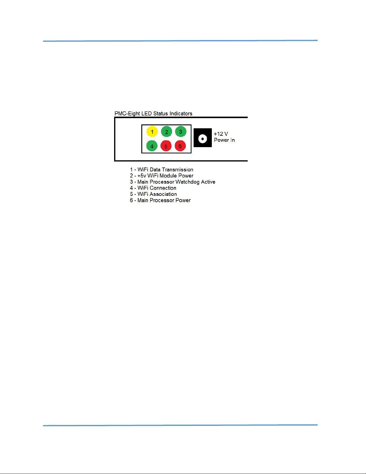
Board Status Indicator LEDs
The model 2A-06B and model 1A-01C PMC-Eight™ processor boards have two LEDs; the RED LED (6) is ON
when power is applied to the board. The GREEN LED (3) is ON indicating the processor status after the
processor firmware boots up and active communications are going on with the processor, and the
watchdog process is active monitoring the communications.
PMC-Eight™ Model 2A-06B Status LEDs
The model 2A-06B PMC-Eight™ RN-131 daughter board has four LEDs; The YELLOW LED (1) is FLASHING
when there is data transmission between the PMC-Eight™ and the host computer application—either the
ExploreStars application or the ASCOM Driver. The RED LED (5) is the WiFi association status and flashes
until a connection to the model 2A-06B SSID (PMC-Eight-xx) of the PMC-Eight™ is made by the host
computer. The GREEN LED (2) is ON when power is applied to the daughter board from the main board.
The GREEN LED (4) FLASHES FAST when a connection is ACTIVE. LED (4) FLASHES SLOW when the module
is waiting on a connection. The model 1A-01C PMC-Eight™ uses the Espressif ESP-WROOM-02 (ESP8266)
WiFi module for wireless communications. There are no communications status lights provided on that
version of the PMC-Eight™.
Switching PMC-Eight™ Communications Channels
You can use the document Explore Scientific PMC-Eight™ Application Note PMC8-AN002: Connecting to
the PMC-Eight™ with a Terminal Program to Configure the RN-131 WiFi Interface and Switching
Between the WiFi Interface and the Serial Interface, and the document Explore Scientific PMC-Eight™
Application Note PMC8-AN003: Switching Between the WiFi Interface and the Serial Interface on the
iEXOS 100™ Mount Controller (available in the Appendix at the end of this document) to switch the
communications channel from WiFi (UDP/TCP) to Serial and back again.
Page 12
Explore Scientific PMC-Eight™ Controller Programmer’s Reference
DOC-ESPMC8-002 Rev. 1.2 2019 March 07 (Firmware 09T10, 10A01 and above)
Copyright ©2016-2019 Explore Scientific, LLC. ExploreScientificUSA.com +1 (866) 252-3811, 1010 South 48th Street, Springdale, AR 72762
11
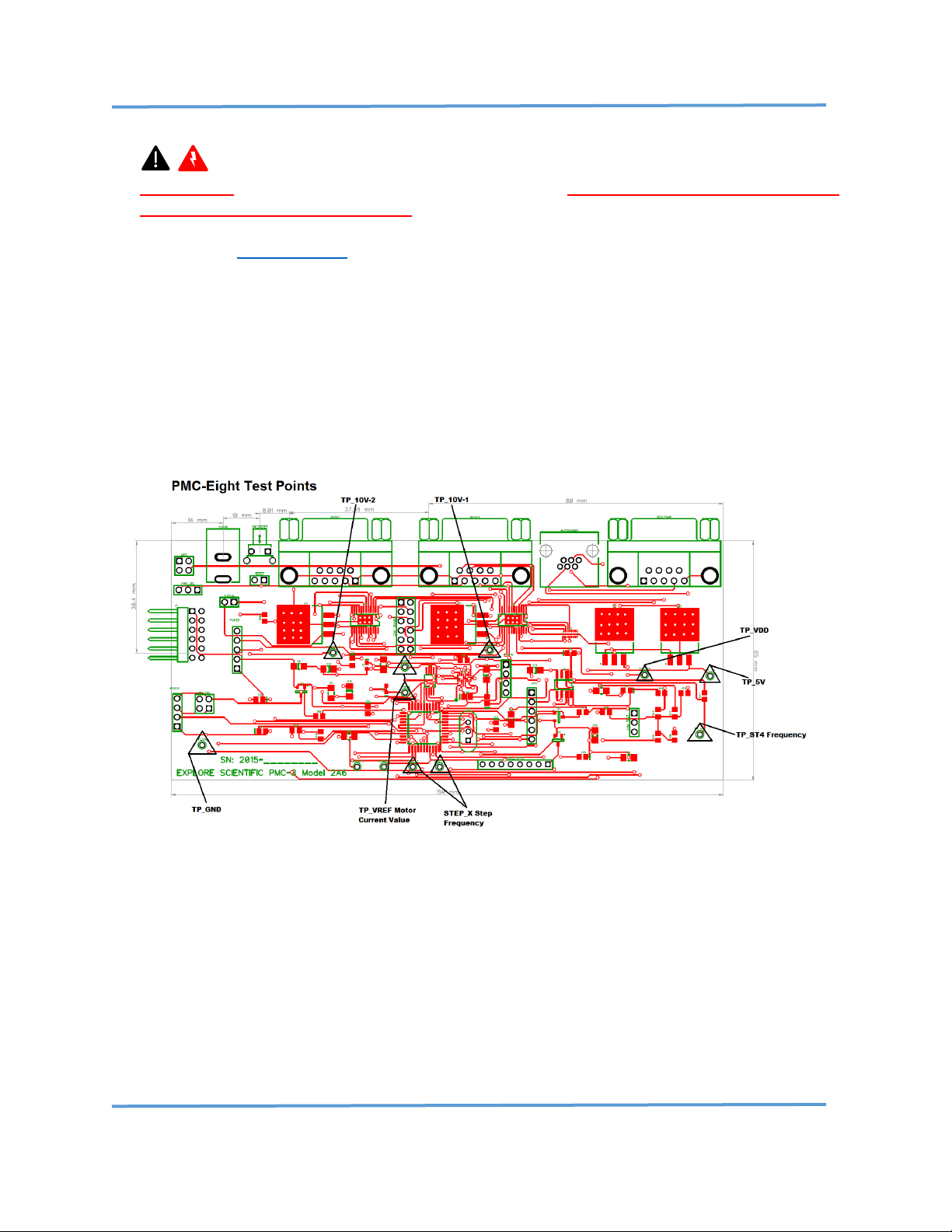
Model 2A Circuit Test Points
WARNING: Prior to opening the PMC-Eight™ enclosure, ensure that you are familiar with all
applicable electrical safety procedures as they apply to working on low-voltage DC circuits. Circuit
failure may occur if proper procedures are not followed when probing the circuitry. See this extensive
discussion on Electrical Safety.
CAUTION: BOARD FAILURE INDUCED THROUGH PROBING THE CIRCUITRY IS NOT COVERED UNDER
THE PMC-Eight™ LIMITED WARRANTY.
There are several test points on the model 2A-06B circuit board assembly (indicated below with a black
triangle) labeled TP_XXXX, such as: TP_GND, TP_VDD, TP_10V-1, TP_10V-2, and TP_5V. There are also test
points to measure the reference voltages for the current limits and the ST4 port frequency and stepper
motor pulses. Headers on the assembly provide access to the RS-232 signals, the power supply voltages
(3.3 Vdc, 5.0 Vdc, 10.0 Vdc, and GND), and the WiFi serial communications signals (COM_TEST header).
PMC-Eight™ Controller Version 2A-06B Test Points
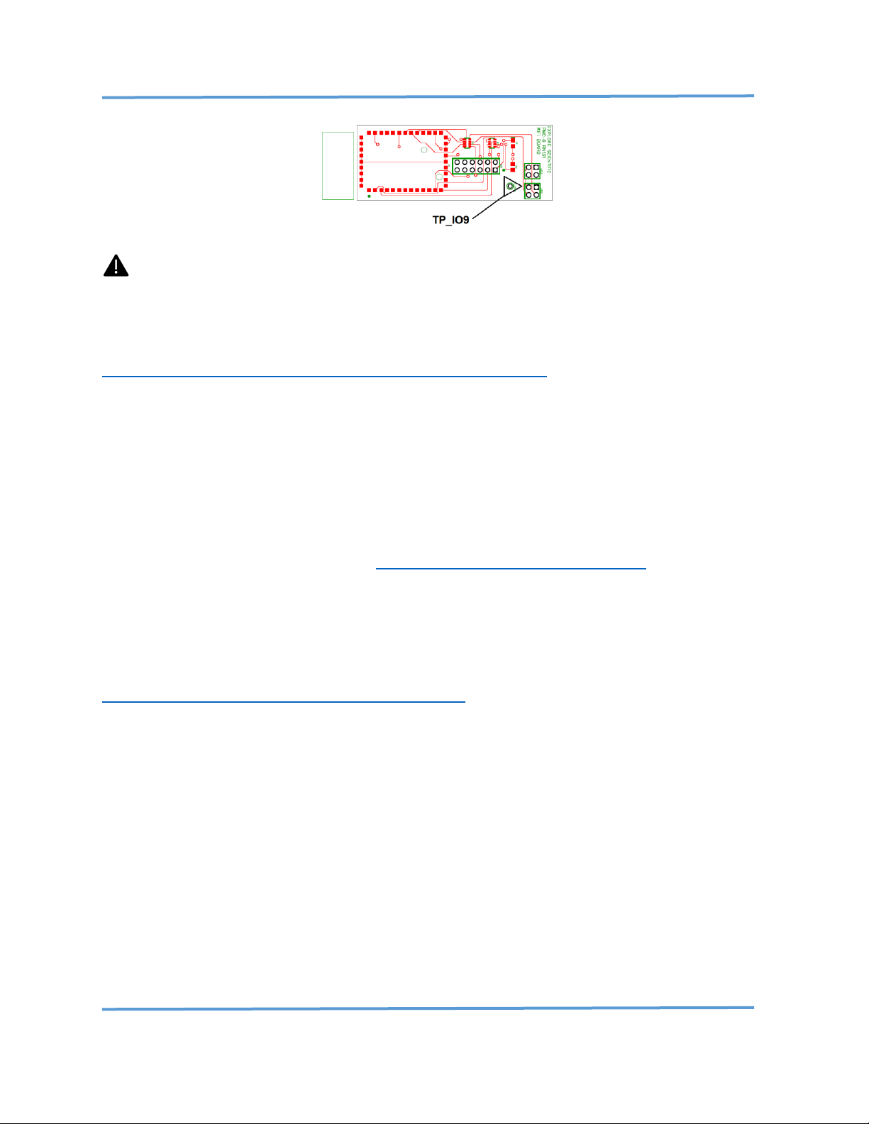
The PMC-Eight™ model 2A-06B WiFi module (Microchip RN-131G) daughter board has a test point
(TP_IO9) used in resetting the module to the Microchip factory defaults. Explore Scientific PMC-Eight™
Application Note PMC8-AN002: Connecting to the PMC-Eight™ with a Terminal Program to Configure
the RN-131 WiFi Interface and Switching Between the WiFi Interface and the Serial Interface (available
in the Appendix at the end of this document) describes in detail how to connect to the Microchip RN-131
Module and restore the PMC-Eight™ default configuration.
Page 13
Explore Scientific PMC-Eight™ Controller Programmer’s Reference
DOC-ESPMC8-002 Rev. 1.2 2019 March 07 (Firmware 09T10, 10A01 and above)
Copyright ©2016-2019 Explore Scientific, LLC. ExploreScientificUSA.com +1 (866) 252-3811, 1010 South 48th Street, Springdale, AR 72762
12
PMC-Eight™ Controller WiFi Daughter Board
CAUTION: Changing the WIFI module configuration from the default factory configuration is at
your own risk.
You can also use Application Note AN002 to configure the Microchip RN-131 Module to communicate on
your Local Area Network (LAN). The Microchip RN-131 WiFly Command Reference Manual is located at
http://ww1.microchip.com/downloads/en/DeviceDoc/50002230B.pdf.
WiFi Channel Selection
In some instances, the WiFi environment is very busy with several SSIDs, and if the PMC-Eight™ WiFi
module is configured to use the same channel as others, this can disrupt the communications, regardless
of the signal strength, and may make the PMC-Eight™ WiFi drop out. The default channel configured in
the RN-131 wireless module is channel 6, which is a popular channel for many WiFi devices. The solution
is to change the WiFi channel. You can do this with the ST4 port (RJ12) dongle included with your PMCEight™ system. You can learn more about how WiFi and channels work in the specification document for
IEEE 802.11. An overview is available here: https://en.wikipedia.org/wiki/IEEE_802.11
Here is the procedure to increment the channel number:
NOTE: You can monitor the channel number selected by the channel change procedure by downloading,
installing, and running the program WiFiInfoView available at:
http://www.nirsoft.net/utils/wifi_information_view.html
1. Power up the PMC-Eight™ and it will boot up (the lights will settle out).
2. Insert the dongle into the Autoguider port (ST4 RJ12).
3. Watch the LEDs cycle, as the system reboots.
4. Remove the dongle.
5. Wait until the LEDs settle down, then Reconnect your tablet to the mount’s SSID.
6. Try to connect the ExploreStars or ASCOM Client application to the PMC-Eight™
7. IF you still cannot connect and see the “Please Wait” message, THEN press the reset button.
8. Repeat steps 2 – 7 as needed.
It is recommended to power down the system and then power it back up between steps 3 and 4, but this
shouldn't be necessary. If the new channel still gives problems, the procedure can be repeated (step 8)
until successful. The number (channel) will increment by one each time the dongle is used to change the
channel and will recycle back to 1 after reaching channel 11. There are 11 channels available in total,
channels 1–11.
Page 14
Explore Scientific PMC-Eight™ Controller Programmer’s Reference
DOC-ESPMC8-002 Rev. 1.2 2019 March 07 (Firmware 09T10, 10A01 and above)
Copyright ©2016-2019 Explore Scientific, LLC. ExploreScientificUSA.com +1 (866) 252-3811, 1010 South 48th Street, Springdale, AR 72762
13
III PMC-Eight™ Controller and Command Language Theory of Operation
Controller Theory of Operation
The PMC-Eight™ Precision Motion Controller is designed to enable the quick and reliable movement of
the telescope OTA to point to any object of interest on the celestial sphere. The controller is made up of
three main electronic subsystems: a) Computer Processor and Memory System, b) Motor Driver System,
and c) Communications Interface.
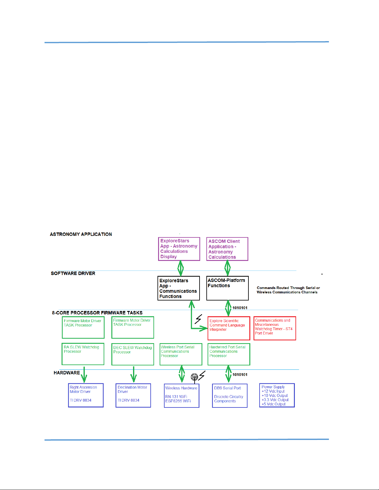
The Computer Processor and Memory System processes and interprets the incoming commands and
provides data output to the communications channels. Eight processors are integrated into the
microcontroller chip (Parallax Propeller Microprocessor P8X32A), each with its own dedicated memory
space and common memory space for sharing information between the processors. There is also a system
RESET/REBOOT momentary push-button switch next to the 12 Vdc Power input. Two processors are
dedicated to communicating with each motor, reading the real-time motor parameters, and generating
the required DIRECTION and RATE motion values real-time to command the motors . One processor is
dedicated to communicating via the RS232 Serial Port via the port driver. One processor is dedicated to
taking the commands and translating them into executable instructions. One processor is dedicated to
monitoring the motor status and reading the Autoguider port. Two processors for the motors are used
only when monitoring the status of the real-time SLEW process. The processors run independently so that
if any one processor fails, it will not affect the operation of the others.
PMC-Eight™ System Architecture
Page 15
Explore Scientific PMC-Eight™ Controller Programmer’s Reference
DOC-ESPMC8-002 Rev. 1.2 2019 March 07 (Firmware 09T10, 10A01 and above)
Copyright ©2016-2019 Explore Scientific, LLC. ExploreScientificUSA.com +1 (866) 252-3811, 1010 South 48th Street, Springdale, AR 72762
14
The Texas Instrument DRV8834 Motor Driver integrated circuit chip (one for each motor channel) is
designed to generate the required low-level stepper motor control/drive signals at the proper voltage and
current levels needed to drive the mount as required. A performance margin is built into the system to
enable the mount to operate over a wide temperature range. These motor driver chips are low power and
very efficient in delivering the power to the stepper motors reliably.
PMC-Eight™ Communications
There are three communication interfaces on the system. The first is the base serial interface using the
RS232 hardware specification and the Parallax recommended interface circuitry to provide basic
communications to transfer firmware and data to the permanent memory of the Computer Processor and
to configure the wireless network Wi-Fi processing module.
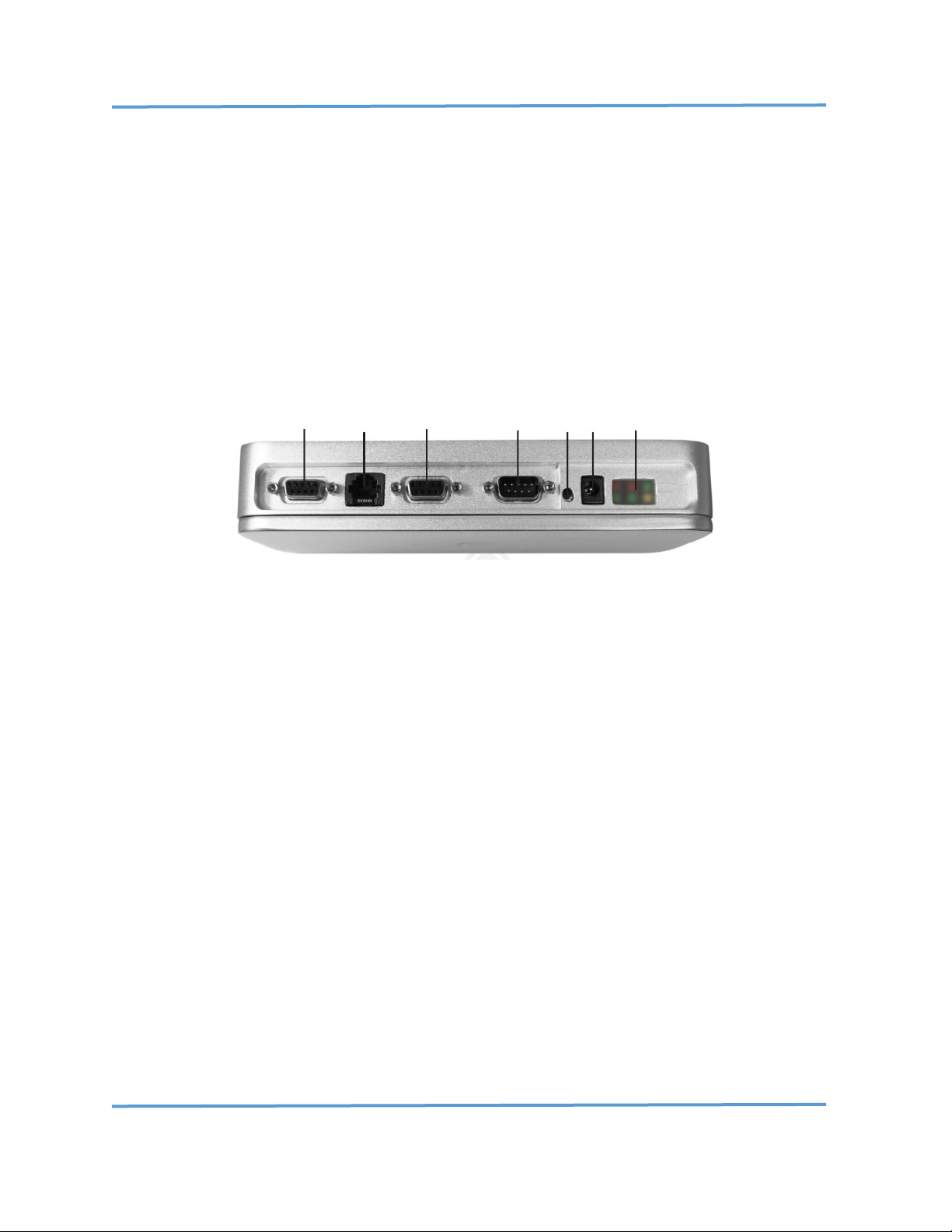
PGMR/ ST4
Serial Autoguider DEC RA RST PWR LEDS
Model 2A PMC-Eight™ connections.
The model 2A-06B serial command processor/interpreter can be accessed via the RS232 port and via the
second interface, the RN-131 wireless network interface. The model 1A-01C serial command
processor/interpreter can be accessed via the mini-USB Type B port and via the second interface, the ESPWROOM-02 (ESP8266) wireless network interface. The third communications channel is via the RJ 6P6C
connector configured as an SBIG ST4 Autoguider Port. This port is also used to change the WiFi Channel,
when needed, using the supplied ST4 port dongle.
PMC-Eight™ Fixed Tracking Rates
There are several fixed tracking rates available for the PMC-Eight™ ASCOM driver and one fixed rate is
available for selection in the ExploreStars™ application. The Sidereal, Solar, Lunar, and Average King rates
are available for selection. The following tables show the tracking rate values and their corresponding
settings in the customer rate section of the ExploreStars application. These rates are pre-defined in the
ASCOM driver.
NOTE: The different mount rates specified in microstep sec-1 are specified to the nearest 0.04 (± 0.02)”arc
sec-1. This value is based on the internal precision of the firmware integer calculation and setting of the
precision tracking rate value. (See
Page 16

Explore Scientific PMC-Eight™ Controller Programmer’s Reference
DOC-ESPMC8-002 Rev. 1.2 2019 March 07 (Firmware 09T10, 10A01 and above)
Copyright ©2016-2019 Explore Scientific, LLC. ExploreScientificUSA.com +1 (866) 252-3811, 1010 South 48th Street, Springdale, AR 72762
15
Application
Object Rate
Solar-Second Rate Value
“arc sec-1
Sidereal-Second Rate Value
“arc sec-1
ExploreStars
Sidereal
15.041
15.000
ASCOM Driver
Sidereal
15.041
15.000
ASCOM Driver
Solar
15.000
14.959
ASCOM Driver
Lunar
14.491
14.451
ASCOM Driver
Average King
15.037
14.996
Fixed Tracking Rate Values
Fixed Tracking Rate
G11 microstep sec-1
@0.28125 arc-sec microstep-1
EXOS 2 & iEXOS 100 microstep sec-1
@0.31250 arc-sec microstep-1
Sidereal
53.32
48.00
Solar
53.20
47.88
Lunar
51.40
46.24
Average King
53.32
48.00
Custom Rate
See Calculation
See calculation
Explore Stars Mount Rate Setting Values
The value of 53.32 microstep sec-1 in the table for the G11 is very close to the actual calculated Average
King rate of 53.3191 microstep sec-1.
The user can also set a custom rate value based on the following equation:
Microstep Rate Value (microstep sec-1) = Sidereal-Second Rate Value (“arc sec-1) / X (“arc microstep-1)
Where X = specific mount’s motor scaling value in “arc microstep-1
For example, if you want to visually observe a comet with the ExploreStars application that is moving
across the sky in RA a little faster than Sidereal, namely at 16.35 “arc sidereal-sec-1 with your G11 mount,
then the calculation would be:
Rate Value = (16.35 “arc sidereal-sec-1/ 0.28125 ”arc microstep-1)
= 58.133 microstep sec-1
= 58.12 microstep sec-1 (rounded to nearest ±0.02 microstep sec-1)
When this value is entered the ExploreStars application would immediately start tracking at that rate.
There would still be a need to move the mount in Declination due to the objects motion in the Declination
axis that is not corrected when in the “square-T” Tracking Mode.
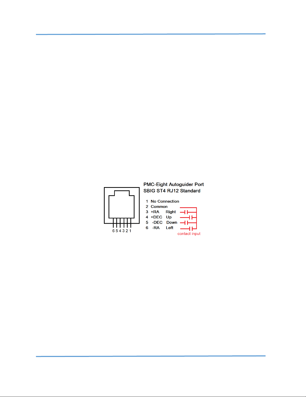
Autoguider (ST4) Port
Both the model 2A and model 1A ST4 port have dedicated interface circuitry to provide contact input
commands into the controller to slowly move the mount in the four cardinal directions to correct for any
tracking errors due to drift in Right Ascension (RA) or Declination (DEC) drift caused by less than perfect
polar alignment.
Page 17
Explore Scientific PMC-Eight™ Controller Programmer’s Reference
DOC-ESPMC8-002 Rev. 1.2 2019 March 07 (Firmware 09T10, 10A01 and above)
Copyright ©2016-2019 Explore Scientific, LLC. ExploreScientificUSA.com +1 (866) 252-3811, 1010 South 48th Street, Springdale, AR 72762
16
The ST4 port on the PMC-Eight™ model 2A-06B uses an analog multiplexer design (VCO) to convert the
four contact inputs sent from the Autoguider camera to the controller into numeric values that can be
processed by the firmware into direction values (N, S, E, W). The analog design requires a factory default
calibration that is included in the firmware. The port meets all the SBIG ST4 standard requirements for
processing a “contact closure” input. Contacts are between each direction pin (N, S, E, W) and the
common pin.
Most guide cameras provide an ST4 compliant “contact closure,” or equivalent, via a MOSFET transistor
circuit using a high-quality component. Some cameras, however, do not have a MOSFET transistor that
provides the correct “contact closure” input resistance (shorted input) but instead provides a higher
resistance input that does not work with the PMC-Eight™ ST4 factory default calibration. In this case,
customers must contact Explore Scientific to have their ST4 input calibrated to their specific camera. See
Appendix VIII.4 “Explore Scientific PMC-Eight™ version 2A-006A/B Autoguider (ST-4) Port Calibration
Procedure (Rev 1.3) Firmware Version 9r4 08162015 AND LATER (2015 August 22)” for details on this
procedure.
The ST4 port on the PMC-Eight™ model 1A-01C uses a digital transistor optocoupler circuit design that
provides a reliable and optically isolated input to the controller from the guide camera system. This
updated digital transistor optocoupler circuit design has also been incorporated into the latest Model 2A07A board design. The significance of this design is that it does not require calibration.
Autoguiding (ST4) Port Pinout
Inputs to the Autoguider port are interpreted by the firmware to adjust the rate according to the Sidereal
Rate Fraction, i.e., Percent Sidereal Rate, configured in the PMC-Eight™ ASCOM driver. The factory default
value is set to 40% or 0.4 x 15.00”arc sec-1, or 6.00”arc sec-1. This value is stored in the system EEPROM as
Parameter 3 (P3) so that when using the ST4 port and RJ12 (6P6C) cable to connect directly to an
Autoguider camera, that camera knows what value to use. The Autoguiding software, PHD2™ corrects any
tracking error by sending pulses to the mount that are different time intervals typically from 20 mS to
200+ mS in length, depending on the amount needed to move the mount back to the target star that
PHD2™ is locked onto.
The total movement needed to correct a position error is the product of correction rate and pulse time.
For example, with a measured position error of 1.07”arc and the Sidereal Rate Fraction set to 0.40 or
6.00”arc second-1, the pulse time would equal the position error 1.07”arc / 6.00”arc second-1, or 0.178
seconds (178 mS).
Page 18

Explore Scientific PMC-Eight™ Controller Programmer’s Reference
DOC-ESPMC8-002 Rev. 1.2 2019 March 07 (Firmware 09T10, 10A01 and above)
Copyright ©2016-2019 Explore Scientific, LLC. ExploreScientificUSA.com +1 (866) 252-3811, 1010 South 48th Street, Springdale, AR 72762
17
Command Language Theory of Operation
The Explore Scientific Command Language commands are used to send data requests and instructions to
control the motors and receive status data back from the hardware. Four basic types of commands are
used to interrogate the controller, two general purpose commands, and two special purpose commands.
The GET and SET commands are used to get and set real-time motor parameters. These are general
purpose commands to get and set a variety of parameters. The two special purpose commands are the
POINT and TRACK commands. Each of these commands are applied to a given motor axis defined by the
AXIS value. With a telescope mount there are 2 predefined axes: AXIS 0: RA/AZ, AXIS 1: DEC/ALT. This
command language can support multiple axis controllers with any number of axes.
The GET and SET commands have several primary parameters dealing with motor operation: DIRECTION,
POSITION, RATE, and TARGET. The three main parameters, DIRECTION, POSITION, and RATE are statically
set and are fixed until the next time they are changed with a SET command. The SET commands for
DIRECTION and RATE are immediate commands and update the values in real time. The SET POSITION
command is used to adjust the motor position coordinates when calibrating the position in reference to
the celestial coordinate system, or when SYNCING with the celestial coordinates of a given object.
The GET commands allow you to interrogate the controller for various real-time parameters, including:
DIRECTION, POSITION, RATE, and TARGET. Other parameters that are available are FIRMWARE VERSION,
SYSTEM INFORMATION via an Index value, and the current TRACKING RATE value.
NOTE: The SYSTEM INFORMATION command is not implemented in firmware versions 9T10, 11, and 12,
and 10A01.
The controller is designed to handle the requirement for fast slews and very slow, precise tracking rates
by implementing two rate types, like a HIGH and LOW in a four-wheel drive vehicle. Standard Rate (SLEW)
and Precision Track Rate (TRACK) commands are provided. The SLEW Rates are 25x faster than the TRACK
Rates. The rate values can be set to any value between 0 and 40000 (decimal), 0x9C40 (hexadecimal). For
the ES/Losmandy G-11, this equates to SLEW rates up to 3.125 sec-1 on each axis1. This allows the system
to SLEW the telescope 180 across the sky in 60 seconds. The TRACK rate allows for setting the RA motor
rate up to 450.00”arc sec-1 with an accuracy of ±0.006”arc sec-1. The standard GET/SET RATE command
sets the SLEW rates. The TRACK command and GET TRACKING RATE command are used to SET/GET a more
precise tracking rate value. This is an equivalent rate selection range of 1:1000000.
The POINT command is a higher-level FIRMWARE command that automatically calculates the necessary
rates to efficiently SLEW to a TARGET. The process algorithm handles the ramping up and down of the
motor rate to manage the inertial load placed on the stepper motors. In addition, the motor current is
carefully managed to provide enough torque while slewing to accurately position the telescope on the
object desired without exceeding the motor capability. The GET/SET commands for FIRMWARE VERSION
and SYSTEM INFORMATION are used to query and set various values such as communications BAUD rate,
Sync Offset Positions, and Axis Scale values.
1
This angular rate is for the ES/Losmandy G-11 mount. Other mounts will slew faster or slower, depending on the
total motor counts for the drive.
Page 19

Explore Scientific PMC-Eight™ Controller Programmer’s Reference
DOC-ESPMC8-002 Rev. 1.2 2019 March 07 (Firmware 09T10, 10A01 and above)
Copyright ©2016-2019 Explore Scientific, LLC. ExploreScientificUSA.com +1 (866) 252-3811, 1010 South 48th Street, Springdale, AR 72762
18
The PMC-Eight™ controller can be remotely rebooted using the BOOT SYSTEM command. This reinitializes
the controller but does not reboot the wireless communications system on the model 2A. You can also
use the BOOT COMMUNICATIONS command to remotely restart the wireless communication system. This
is also independent of the system controller and does not reset the motor drivers or the current motor
counts. To reboot the entire system, you must remove power and reapply power to the controller system.
The Get Motor Position Command returns the motor position string in Hex Value. The string is in the
format “FFFFFF”. The value returned is in the range 0x000000 to 0xFFFFFF, where positive values range
from 0x000000 to 0x7FFFFF and the negative values range from 0xFFFFFF to 0x800000. The scaling of the
motor gear position limits the actual values used to slew the motors. The two motors are on the RA and
the DEC axis of a German Equatorial Mount (GEM). The angular range for counts depends on the motor
count scaling value and is calculated as follows:
NOTE: This example uses the ES/Losmandy G-11 mount.
The ES/Losmandy G-11 uses direct coupled stepper motors whose motor scaling value uses only the wheel
tooth count, the stepper motor steps, and the driver microstep value. The ES/Losmandy G-11 uses a 360tooth wheel and 400-step motors. The driver uses 32 microsteps step-1. The total count for a 360-degree
rotation of both the RA and DEC axis is equal to 360 teeth * 400 steps * 32 microsteps, which is equal to
4,608,000 counts per 360-degree rotation. The angular motion per step in “arc is equal to the total number
of “arc/4,608,000 counts. 360 degrees is equal to 360 x 60 x 60”arc or 1,296,000”arc. The “arc count-1 is
equal to 1,296,000/4,608,000 or 0.28125”arc count-1.
So, in the case of the ES/Losmandy G-11, one rotation in RA, or 24 hours (sidereal time) is equal to
4,608,000 counts or in Hex, 0x465000. The RA value counts positive and negative from the Meridian+6
hours or Local Mean Sidereal Time (LMST)+6 hours. On a GEM mount, the way the telescope is pointing
is an important consideration when determining the motor counts. As the GEM is tracking, when the
telescope gets to the Meridian, a maneuver called a “Meridian Flip” is performed. To help explain, this
here is the sequence of events.
NOTE1: This description is only valid for mounts located in the Northern Hemisphere. The ASCOM driver
detects the hemisphere where the mount is located via the LATITUDE value set in the configuration dialog
box and adjusts the driven RA direction accordingly. The PARK reference position is either the NCP or SCP
(North/South Celestial Pole), with a corresponding motor count on RA and DEC of 0 (0x000000).
NOTE2: This description only applies to the ES/Losmandy G-11 because the description of the motor
counts increasing or decreasing depends on the gear direction for this mount.
1. The mount is pointing the telescope to an object in the EAST. The mount is tracking at
SIDEREAL rate toward the WEST, and the RA motor counts are POSITIVE and INCREASING. The
RA motor counts are in the range 0 (0x000000) moving toward 1152000 (0x119400). The
object the mount is pointing to is also NORTH of the ECLIPTIC or has a positive DEC value
between +0.000 and +90.000 degrees. This is a fixed DEC motor count value between 0
(0x000000) and 1152000 (0x119400) when WpE. The DEC axis counts INCREASE going SOUTH
from the NCP. Objects that are SOUTH of the ECLIPTIC have values between 1152000
(0x119400) and 2304000 (0x232800). These values are from -0.000 to -90.000 degrees. This
pointing position is called “West Pointing East” or WpE. This means that the telescope is WEST
Page 20

Explore Scientific PMC-Eight™ Controller Programmer’s Reference
DOC-ESPMC8-002 Rev. 1.2 2019 March 07 (Firmware 09T10, 10A01 and above)
Copyright ©2016-2019 Explore Scientific, LLC. ExploreScientificUSA.com +1 (866) 252-3811, 1010 South 48th Street, Springdale, AR 72762
19
of the PIER and pointing EAST of the MERIDIAN. In the ASCOM driver, this is referred to as
“PierWEST,” where the Hour Angle (HA) is less than zero (HA<0) and DECREASING in value.
2. When the mount RA axis finally arrives at the LMST value of 1152000 (0x119400), then the
mount should execute a Meridian Flip. The flip maneuver SLEWS the RA axis back to the EAST
equal to approximately 12 hours of RA or 180 degrees. This means that the RA motor counts
DECREASE from 1152000 (0x119400) moving toward 0 (0x000000) and then continue to 1152000 (0xEE6C00). At the same time, the DEC axis SLEWS to the NORTH, DECREASING the
motor counts, passing through the NCP while crossing 0 (0x000000) counts and continuing
down toward the object’s DEC motor count value between 0 (0x000000) and -2304000
(0xDCD800) counts.
3. At the completion of the flip maneuver, the RA tracking begins to drive at the SIDEREAL rate
toward the WEST again, with the RA axis counts again INCREASING in value. The RA axis counts
are in the range of -1152000 (0x119400) moving toward 0 (0x000000). In this mode, the DEC
axis counts INCREASE going NORTH from -90.000 to +90.000 degrees or from -2304000
(0xDCD800) to 0 (0x000000) counts when EpW. This position, post Meridian Flip, is called
“EAST Pointing WEST” or EpW. This means the telescope is EAST of the PIER and pointing
WEST of the MERIDIAN. In the ASCOM driver, this is referred to as “PierEAST” where the HA
is more than zero (HA>0) and INCREASING in value.
In summary, the motor count ranges for the different pointing quadrants are defined as specific values
for each quadrant pointed to. The Sidereal Past is defined as object RA values that are LESS than the LMST
value (RA<ST) and is WEST of the MERIDIAN. The Sidereal Future is defined as object RA values that are
GREATER than the LMST value (RA>ST) and is EAST of the MERIDIAN. For example, if the LMST is currently
14:32:26.0, then 14:35:00.0 would be in the Sidereal Future, and 14:30:00.0 would be in the Sidereal Past.
When the telescope is WpE (target object RA is in the Sidereal Future):
1. The counterweight is east of the pier.
2. The telescope is west of the pier.
3. RA motor counts increase, tracking West: 0 < RA < 1152000.
4. DEC motor counts increases from NCP: 0 < N < 1152000 < S < 2304000: SCP.
When WpE, LMST is at motor count value 1152000 and is the position where the counterweight bar is
horizontal to the horizon.
When telescope is EpW (target object RA is in the Sidereal Past):
1. The counterweight is west of the pier.
2. The telescope is east of the pier.
3. RA motor counts increase, tracking West: -1152000 < RA < 0.
4. DEC motor counts increase from SCP: -2304000 < S < -1152000 < N < 0: NCP.
When EpW, LMST is at motor count value -1152000 and is the position where the counterweight bar is
horizontal to the horizon.
Page 21

Explore Scientific PMC-Eight™ Controller Programmer’s Reference
DOC-ESPMC8-002 Rev. 1.2 2019 March 07 (Firmware 09T10, 10A01 and above)
Copyright ©2016-2019 Explore Scientific, LLC. ExploreScientificUSA.com +1 (866) 252-3811, 1010 South 48th Street, Springdale, AR 72762
20
IV PMC-Eight™ ASCII Command Language
The 16 base PMC-Eight™ ASCII Commands allow you to control the mount in various ways to set the
tracking rates, slew the mount to a position, and various other functions. Each of the command strings
ends with the “!” (bang/shriek/exclamation) symbol except when entering and exiting the Diagnostic
Mode. The Diagnostic Mode is used to enable the Simple Base ASCII Command Interpreter within the
firmware. These commands are used internally by Explore Scientific employees in troubleshooting lowlevel motor performance functions. The default Command mode enables both the JOC and ES Command
Interpreters when the PMC-Eight™ Controller boots. The Simple Base ASCII Commands are defined further
below.
The JOC Command Language is a BINARY based command system that uses a pre-defined header plus
command and argument values.
NOTE: The JOC command language is only used in the ExploreStars application internal communications
driver. The PMC-Eight™ ASCOM driver uses the Explore Scientific Command Language documented
here.
Enter ASCII Diagnostic Mode:
Command: "%%%"
Response: "Diagnostic Mode ENABLED%"
NOTE: In the current version of the firmware (09T10 or later), entering the ASCII Diagnostic Mode will
continuously display the analog value (Hex) for the ST4 Interface. This is used to acquire the data
for calibrating the ST4 interface with a user’s camera. The other low-level motor commands can
be entered while the display is continuously showing the ST4 values.
Exit ASCII Diagnostic Mode:
Command: "###"
Response: "Diagnostic Mode DISABLED#"
To manually issue commands to the PMC-Eight™ controller, you must follow the instruction in Appendix
VIII.2 (Model 2A-06B) and VIII.3 (Model 1A-01C) of this document. You will use the Parallax Serial
Terminal program to communicate with the controller.
Simple Base PMC-Eight™ Commands
The Simple Base PMC-Eight™ Commands (base commands) deal with the root motor control features and
allow you to start and stop each motor and set the speed, microstep, and direction values.
NOTE: You must enter Diagnostic Mode to enable the base commands. The firmware is set to continuously
display the Autoguider port values. The command interpreter will still process the base commands when
entered.
Page 22

Explore Scientific PMC-Eight™ Controller Programmer’s Reference
DOC-ESPMC8-002 Rev. 1.2 2019 March 07 (Firmware 09T10, 10A01 and above)
Copyright ©2016-2019 Explore Scientific, LLC. ExploreScientificUSA.com +1 (866) 252-3811, 1010 South 48th Street, Springdale, AR 72762
21
“B” Command: B <enter>
BOOT Command – Performs a reboot of the controller
“F” Command: FX <enter> where X is the motor channel number 0 (RA), 1 (DEC).
FAULT Command—GETS the status of the DRV8834 motor driver chip fault indicator. The chip
provides a fault indication for a detection of overcurrent, overtemperature, short circuit, and
undervoltage lockout conditions. See the Texas Instruments DRV8834 Datasheet for detailed
information.
“R” Command: RXYYYYY <enter> where X is the RA motor (channel 0) direction and YYYYY is the decimal
motor speed (microsteps/second) internally limited to 40000 microsteps/second.
RA MOTOR Command – SETS the RA motor precision tracking speed in (microsteps/second)/25.
To stop the motor, issue R00 <enter> command.
“D” Command: DYYYYY <enter> where Y is the DEC motor decimal motor speed (microsteps/second).
DEC MOTOR Command—SETS the DEC motor slew speed in (microsteps/second). To stop the
motor, issue D0 <enter> command.
“M” Command: MX <enter> where X is the microstep multiple index value.
MICROSTEP Command—SETS the micro-stepping multiplier value according to the equation:
Multiplier Value = 2X, i.e., for an X value of 3, 23 equals a scaling of 8 microsteps/step.
“X” Command: XX <enter> where X is the direction value for the RA axis.
RA DIR Command—SETS the RA axis direction value, 0 (clockwise), 1 (counterclockwise).
“Y” Command: YX <enter> where X is the direction value for the DEC axis.
DEC DIR Command—SETS the DEC axis direction value, 0 (clockwise), 1 (counterclockwise).
“P” Command: PX <enter>, PXYYYYYY <enter> where X is the parameter number and YYYYYY is the value
to set.
PARAMETER Command—GETS and SETS the stored parameter values where X is 0-9, and YYYYYY
is a decimal value. These parameters are pre-defined. The PX <enter> command GETS the current
value for parameter X, the PXYYYYYY <enter>
command SETS the current value for Parameter X with value YYYYYY.
The current predefined parameters (Firmware 9T10, 9T11, 9T12, 10A01, 10B01) are:
P0—BAUD Rate: 9600-115,200 DEFAULT = 115,200
P1—Communications Channel: 0 (Serial), 1 (Wireless) DEFAULT = 1
P2—Network Protocol: 0 (TCP/IP), 1 (UDP/IP) DEFAULT = 1
P3—Autoguider (ST4) port Sidereal Rate Fraction %: 0-100 DEFAULT = 40
This value should not be changed; values less than 115,200 affect the control response when
using the ExploreStars application and render the application inoperable without modification.
Page 23

Explore Scientific PMC-Eight™ Controller Programmer’s Reference
DOC-ESPMC8-002 Rev. 1.2 2019 March 07 (Firmware 09T10, 10A01 and above)
Copyright ©2016-2019 Explore Scientific, LLC. ExploreScientificUSA.com +1 (866) 252-3811, 1010 South 48th Street, Springdale, AR 72762
22
V PMC-Eight™ ASCII Command Language Syntax
The Explore Scientific Controller Command Language is an ASCII based command language system that
can be parsed by a computer program to determine the desired control action and is human readable,
making it easy to interpret and form messages when coding once the syntax is mastered. This language
specification is implemented in the controller FIRMWARE version ES06B9T2 and later.
NOTE1: ASCII Commands are CASE SENSITIVE. Data values are specified as Hex String Values, e.g.,
“FFD47A”. These values are converted to Long Integers (32-bit) within the FIRMWARE. Generally,
when a REQUEST command is sent, the RESPONSE includes the corresponding request syntax so
that future asynchronous capabilities can be accommodated in the FIRMWARE.
NOTE2: The header “ES” is required, items in brackets {} are required, items in parenthesis () are optional
depending on the command, and the “!” or shriek is required as an End-Of-Line (EOL) marker.
ONLY 1 (one) of each command identifier is to be specified in each {} grouping.
Request Syntax:“ES{GSTPBR}{prtdvix}(A)(D) (XXXX)(YYYYYY)(ZZZZZZ)!”
Response Syntax:“ES{GSTPBR}{prtdvix}(A)(D) (XXXX)(YYYYYY)(ZZZZZZ)!”
Header String: “ES” Explore Scientific Language Command
Base Commands: “G” Get command
“S” Set Command
“T” Track Command
“P” Point Command
“B” Boot Command
“R” Reset Communications Command
NOTE3: Command Parameter Codes only apply to the Get “G” and Set “S” Base Commands.
Command Parameter Code: “p” Position value
“r” Slew Rate value
“t” Target value
“d” Direction value
“v” Version value
“i” System Information value
Axis Values: “0” Right Ascension / Azimuth Axis
“1” Declination / Altitude Axis
Direction Values: “0” Clockwise
“1” Counter-Clockwise
NOTE4: Axis Direction value is determined by looking at the motor from the shaft end.
NOTE5: The following System Information Values are not fully implemented in firmware versions 09t10
and previous. Only values “0x00” and 0x01” are implemented but they are not queryable in these
firmware versions.
Page 24

Explore Scientific PMC-Eight™ Controller Programmer’s Reference
DOC-ESPMC8-002 Rev. 1.2 2019 March 07 (Firmware 09T10, 10A01 and above)
Copyright ©2016-2019 Explore Scientific, LLC. ExploreScientificUSA.com +1 (866) 252-3811, 1010 South 48th Street, Springdale, AR 72762
23
System Information Values: “0x00” WIRELESS Enabled {True=1, False=0)
“0x01” BAUD Rate {2400,9600…115200}
“0x02” AXIS 0 SCALE Counts (RA/AZ Axis) {0xFFFFFF}
“0x03” AXIS 1 SCALE Counts (DEC/ALT Axis) {0xFFFFFF}
“0x04” AXIS 0 OFFSET Counts (RA/AZ Axis) {0XFFFFFF}
“0x05” AXIS 0 OFFSET Counts (DEC/ALT Axis) {0XFFFFFF}
“06” TBD … “0F” TBD
Not implemented as of Firmware 09T10, 10A01
NOTE6: The AXIS SCALE Counts value is related to the physical configuration of the mount’s gear ratio,
stepper motor configuration, and controller motor driver configuration. The ES/Losmandy G-11
mount’s AXIS SCALE Count values are calculated using the following parameters: Worm/Wheel
Ratio 1:360, Stepper Motor Steps/Revolution 400, Motor Attachment Gear Ratio 1:1, and Motor
Driver Micro-stepping ratio: 1:32. These parameters apply to both the RA and DEC axes on the
ES/Losmandy G-11 mount. The calculation for the RA and DEC AXIS SCALE Counts is: 360 x 1 x 400
x 32 = 4,608,000 (0x465000)2. The mount’s movement in “arc/count can be calculated by dividing
1,296,000 by the AXIS SCALE Counts. In this case, the mount’s resolution is
(1,296,000/4,608,000)”arc count-1 or 0.28125”arc count-1. Because the PMC-Eight™ Controller
uses the Sidereal Second as the standard for internal hardware time-keeping, the Sidereal
Tracking Rate of 15.000”arc sec-1 would be equivalent to a COUNT RATE value of (15.000”arc sec
-
1
) / (0.28125”arc count-1) = 53.333 counts sec-1. The mean Lunar Tracking Rate of 14.451”arc sec
-
1
equates to a COUNT RATE of 51.40 counts sec-1. The mean Solar Tracking Rate of 15.041”arc
sec-1 equates to a COUNT RATE of 53.48 counts sec-1.
Mount
UNITS
ES/Losmandy G-11
EXOS 2 & iEXOS 100
Total Counts
microsteps
4608000
4147200
Motor Counts
steps/revolution
400
200
Motor Model
number
17HM19-1684S
11HS20-0674S
Motor Frame
type
NEMA 17
NEMA 11
Primary Gear Teeth
count
360
144
Secondary Gear Ratio
NA
1
4.5
Motor Current
mA
900
600
Sidereal Tracking Rate
microsteps/second
53.333
48.000
Motor Scale
”arc/micro-step
0.28125
0.31250
Maximum Step Frequency
Hz
40000
40000
Maximum Slew Rate
°/second
3.125
3.472
Mount Stepper Motor Drive Parameters
Firmware version 9T12 increases motor current to 1300 mA
2
See Table on page 16 for the fixed tracking rate count calculation and parameter values for each of the Explore
Scientific mounts.
Page 25

Explore Scientific PMC-Eight™ Controller Programmer’s Reference
DOC-ESPMC8-002 Rev. 1.2 2019 March 07 (Firmware 09T10, 10A01 and above)
Copyright ©2016-2019 Explore Scientific, LLC. ExploreScientificUSA.com +1 (866) 252-3811, 1010 South 48th Street, Springdale, AR 72762
24
The following table lists the command language and the command request/response syntax. A description
of all the commands is listed here for your reference and usage. Pay close attention to the command notes
for any special requirements or restrictions on the command’s usage.
GET Command
Name
Parameter
“ESGp!”
Get Axis Current Position
Axis
“ESGr!”
Get Axis Current Rate
Axis
“ESGt!”
Get Axis Current Target
Axis
“ESGd!”
Get Axis Current Direction
Axis
“ESGv!”
Get System Firmware Version
None
“ESGi!”
Get System Information
Value Index
SET Command
Name
Parameter
“ESSp!”
Set Axis Current Position
Axis, Position
“ESSr!”
Set Axis Current Rate
Axis, Rate
“ESSd!”
Set Axis Current Direction
Axis, Direction
“ESSi!”
Set System Information
Value Index
TRACK Command
Name
Parameter
“ESTr!”
Set Precision Tracking Rate
Axis, Rate
POINT Command
Name
Parameter
“ESPt!”
Point to Target Position
Axis, Position
SWAP Command
Name
Parameter
“ESX!”
Swap Primary Serial Interface
None
“ESY!”
Swap Network Protocol
None
RESET Command
Name
Parameter
“ESR!”
Reset WiFi Comm Controller
None
BOOT Command
Name
Parameter
“ESB!”
Reboot Motor Controller
None
List of PMC-Eight™ ASCII Commands
Page 26

Explore Scientific PMC-Eight™ Controller Programmer’s Reference
DOC-ESPMC8-002 Rev. 1.2 2019 March 07 (Firmware 09T10, 10A01 and above)
Copyright ©2016-2019 Explore Scientific, LLC. ExploreScientificUSA.com +1 (866) 252-3811, 1010 South 48th Street, Springdale, AR 72762
25
The firmware code modules have the following information as a ready reference to the command syntax.
NOTE: The firmware (version 09T10+, 10A01) source code is Explore Scientific, LLC proprietary and IS NOT
available for inspection.
' -----------------------------------------------------------------------------' Explore Scientific Command Language
' See programmers reference manual for details on command syntax
'
' ES Internal Command Return Strings
' -----------------------------------------------------------------------------' Internally, HEX Return Strings are used for the ES commands to separate out the
' different ones. HEX values from 0x00 to 0x3F are used for the Explore Scientific
' commands. Items in {} are required, items in () are optional depending on the
' command. A=axis, D=direction, XXXX=rate, YYYYYY=position, ZZZZZZZZ=parameter value
'
' ES{G,S,T,P,Y,X,R,B}{p,r,t,d,v,i,x}(A)(D)(XXXX)(YYYYYY)(ZZZZZZZZ)!
'
' G_! 0x00 FUTURE ESG_!
' Gp! 0x01 get current axis position value ESGpA!
' Gr! 0x02 get current axis rate value ESGrA!
' Gt! 0x03 get current axis target value ESGtA!
' Gd! 0x04 get current axis direction value ESGdA!
' Gv! 0x05 get current firmware version ESGv!
' Gi! 0x06 get current system information ESGiZ!
' Sp! 0x11 set axis position value ESSpAYYYYYY!
' Sr! 0x12 set axis slew rate value ESSrAXXXX! (Allows full range of rates)
' Sd! 0x14 set axis direction value ESSdAD!
' Si! 0x16 set system information ESSiAZZZZZZZZ! (A is the parameter index)
' Tr! 0x22 set tracking rate value ESTrXXXX!(Track rate only applies to RA)
' Pt! 0x31 point (slew) to target using ramps ESPtAYYYYYY!
' Y! 0xFC Switch IP Protocol (UDP/TCP) ESY!
' X! 0xFD Switch Communications Mode (WIFI/SER) ESX!
' R! 0xFE Reset Communications Controller ESR!
' B! 0xFF Boot PMC-Eight Controller ESB!
' ------------------------------------------------------------------------------
Page 27

Explore Scientific PMC-Eight™ Controller Programmer’s Reference
DOC-ESPMC8-002 Rev. 1.2 2019 March 07 (Firmware 09T10, 10A01 and above)
Copyright ©2016-2019 Explore Scientific, LLC. ExploreScientificUSA.com +1 (866) 252-3811, 1010 South 48th Street, Springdale, AR 72762
26
Command Language Syntax
“G” GET Commands:
“ESGp” GET AXIS CURRENT POSITION VALUE
REQUEST: “ESGpA!”
RESPONSE: “ESGpAYYYYYY!”
Example: Get Current RA Axis Position Value
REQUEST: “ESGp0!”
RESPONSE: “ESGp0FF37DA!”
NOTE: Data values are specified as Hex String Values.
“ESGr” GET AXIS CURRENT RATE VALUE
REQUEST: “ESGrA!”
RESPONSE: “ESGrAXXXX!”
Example: Get Current RA Axis Rate Value
REQUEST: “ESGr0!”
RESPONSE: “ESGr037DA!”
NOTE: Data values are specified as Hex String Values.
“ESGt” GET AXIS CURRENT TARGET VALUE
REQUEST: “ESGtA!”
RESPONSE: “ESGtAYYYYYY!”
Example: Get Current RA Axis Target Value
REQUEST: “ESGt0!”
RESPONSE: “ESGt062E4D7!”
NOTE: Data values are specified as Hex String Values.
“ESGd” GET AXIS CURRENT DIRECTION VALUE
REQUEST: “ESGdA!”
RESPONSE: “ESGdAD!”
Example: Get Current RA Axis Direction Value
REQUEST: “ESGd0!”
RESPONSE: “ESGd01!”
NOTE: Data values are specified as Hex String Values.
Page 28

Explore Scientific PMC-Eight™ Controller Programmer’s Reference
DOC-ESPMC8-002 Rev. 1.2 2019 March 07 (Firmware 09T10, 10A01 and above)
Copyright ©2016-2019 Explore Scientific, LLC. ExploreScientificUSA.com +1 (866) 252-3811, 1010 South 48th Street, Springdale, AR 72762
27
“ESGv” GET CURRENT FIRMWARE VERSION VALUE
REQUEST: “ESGv!”
RESPONSE: “ESGvZZZZZZZZ!”
Example: Get Current FIRMWARE Version Value
REQUEST: “ESGv!”
RESPONSE: “ESGvES6B09U0!” (version ES6B09U0)
NOTE1: Data values are specified as character string values.
NOTE2: The returned string is a combination of the hardware version “6B” and the firmware
version “09U0”. This is currently hard coded in the firmware for each firmware release.
“ESGi” GET CURRENT SYSTEM INFORMATION VALUE
NOTE: Not implemented in this version.
REQUEST: “ESGiX!”
RESPONSE: “ESGiXZZZZZZZZ!”
Example: Get Current System Information 1 (BAUD Rate) Value
REQUEST: “ESGi1!”
RESPONSE: “ESGi10001C200!” (decimal 115,200 BAUD)
Example: Get Current System Information 03 (DEC Maximum) Value
REQUEST: “ESGi3!”
RESPONSE: “ESGi300465000!” (decimal 4,608,000 DEC MAX)
NOTE: Data values are specified as Hex String Values.
“ESGx” GET CURRENT PRECISION TRACKING RATE VALUE
REQUEST: “ESGx!”
RESPONSE: “ESGxXXXX!”
Example: Get Current Precision Tracking Rate Value
REQUEST: “ESGx!”
RESPONSE: “ESGx0535!”
NOTE1: Data values are specified as Hex String Values.
NOTE2: The Get Tracking Rate value only applies to Axis 0, or the RA Axis.
The Precision Tracking value is calculated by multiplying the nominal calculated Rate
Counts (for ES/Losmandy G-11) by 25, i.e.,
Rate Counts = rate “arc sec-1/0.28125 count-1
The calculated precision tracking value for a sidereal rate of 15.000”arc sidereal-sec-1 is:
Precision Tracking value = (15.000 / 0.28125) * 25
= 53.333 * 25
= 1333 (decimal)
= 0x0535 (hexadecimal)
Page 29

Explore Scientific PMC-Eight™ Controller Programmer’s Reference
DOC-ESPMC8-002 Rev. 1.2 2019 March 07 (Firmware 09T10, 10A01 and above)
Copyright ©2016-2019 Explore Scientific, LLC. ExploreScientificUSA.com +1 (866) 252-3811, 1010 South 48th Street, Springdale, AR 72762
28
The Tracking Rate value is accurate to ±0.02 counts sec-1, so the resulting count rate is
equal to 53.32 counts sec-1. This command accommodates precision count rates from 0.00
to 2621.44 counts sec-1, which is equivalent to precision rate values of 0 to 7.5’ arc sec-1
or about 0.1 sec-1.
“S” SET Commands:
The RESPONSE to the SET Commands in general mimics the value returned when using the GET
Commands. The RESPONSE syntax will be identical to the corresponding GET Command. This is
implemented this way to simplify the coding of any function that is written to process the RESPONSE
string.
“ESSp” SET AXIS POSITION VALUE
REQUEST: “ESSpAYYYYYY!”
RESPONSE: “ESGpAYYYYYY!”
Example: Set RA Axis Position Value
REQUEST: “ESSp0FF37DA!”
RESPONSE: “ESGp0FF37DA!”
NOTE1: Data values are specified as Hex String Values.
NOTE2: Setting the Axis Position Value UPDATES it to a NEW value on the fly without slewing the
mount in any way. This can be used to recalibrate the axis pointing position when syncing the axis
to an external reference point provided by a reference source such as a star catalog or
planetarium program. The Axis Position Value is only set to 0 (zero) when the axis is in its PARK
position. When used in the ASCOM Telescope driver, the Position value is converted back and
forth between the Motor Count Hex Value and the Degrees/Minutes/Seconds System. The
defined PARK position for a GEM mount is the NCP/SCP. This NCP/SCP position has coordinates
RA LST (07:43:22.00) + 06:00:00.00, DEC +90 00m 00.0s (NCP), or DEC -90 00m 00.0s (SCP)
“ESSr” SET AXIS TRACKING RATE VALUE
REQUEST: “ESSrAXXXX!”
RESPONSE: “ESGrAXXXX!”
Example: Set Current RA Axis Rate Value
REQUEST: “ESSr037DA!”
RESPONSE: “ESGr037DA!”
NOTE1: Data values are specified as Hex String Values.
NOTE2: Setting the Axis Tracking Rate Value UPDATES it to a NEW value on the fly without
initiating a ramp to rate process. This can be used to adjust the Tracking Rate for
Sidereal, Lunar, Solar, and any other object that you may want to track (within reason).
The nominal Sidereal Rate for the RA axis is 53.333 counts sec-1 for the ES/Losmandy G-
11. The nominal Lunar Rate for the RA axis is 51.387 counts sec-1. To improve the
resolution for setting the Axis Rate, the floating-point value for counts sec-1 needs to be
multiplied by 25 and rounded to the nearest integer to develop the value used in sending
Page 30

Explore Scientific PMC-Eight™ Controller Programmer’s Reference
DOC-ESPMC8-002 Rev. 1.2 2019 March 07 (Firmware 09T10, 10A01 and above)
Copyright ©2016-2019 Explore Scientific, LLC. ExploreScientificUSA.com +1 (866) 252-3811, 1010 South 48th Street, Springdale, AR 72762
29
the REQUEST, e.g., Sidereal Rate = 53.333 Counts sec-1, 25 x 53.333 = 1333.325 or 1333
integer. Finally convert the value 1333 Rate to Hex: 0x0535.
“ESSt” SET AXIS TARGET VALUE
REQUEST: “ESStAYYYYYY!”
RESPONSE: “ESGtAYYYYYY!”
Example: Set Current RA Axis Target Value
REQUEST: “ESSt062E4D7!”
RESPONSE: “ESGt062E4D7!”
NOTE1: Data values are specified as Hex String Values.
NOTE2: Setting the Axis Target Value UPDATES it to a NEW value on the fly and initiates a ramping
rate process. This can be used to reposition the Target in the middle of a POINT command.
When used in the ASCOM Telescope driver, the Target value is converted back and forth
between the Motor Count Hex Value and the Degrees/Minutes/Seconds System. See the
Supplemental Command Discussion section for details.
“ESSd” SET AXIS DIRECTION VALUE
REQUEST: “ESSdAX!”
RESPONSE: “ESGdAX!”
Example: Set Current RA Axis Target Value
REQUEST: “ESSd01!”
RESPONSE: “ESGd01!”
NOTE1: Data values are specified as Hex String Values.
NOTE2: The direction values as looking at the shaft end of the motor are 0x0 for clockwise, 0x1
for counterclockwise.
NOTE3: Setting the Axis Direction Value UPDATES it to a NEW value on the fly. In general, this
should only be done when the motor RATE value is zero or close to zero because it puts
inertial stress on the motor and gear system of the mount and may result in lost motor
counts and slipping of the motor position.
“ESSi” SET CURRENT SYSTEM INFORMATION VALUE
NOTE: Not implemented in versions 09T12, and 10A01 and previous.
REQUEST: “ESSiXZZZZZZZZ!”
RESPONSE: “ESGiXZZZZZZZZ!”
Example: Set Current System Information #1 (BAUD Rate) Value
REQUEST: “ESSi10001C200!”
RESPONSE: “ESGi10001C200!” (decimal 115,200 BAUD)
Example: Set Current System Information #3 (DEC Maximum) Value
REQUEST: “ESGi300465000!”
RESPONSE: “ESGi300465000!” (decimal 4,608,000 DEC MAX)
Page 31

Explore Scientific PMC-Eight™ Controller Programmer’s Reference
DOC-ESPMC8-002 Rev. 1.2 2019 March 07 (Firmware 09T10, 10A01 and above)
Copyright ©2016-2019 Explore Scientific, LLC. ExploreScientificUSA.com +1 (866) 252-3811, 1010 South 48th Street, Springdale, AR 72762
30
NOTE: Data values are specified as Hex String Values.
“T” TRACK Command:
“ESTr” SET PRECISION TRACKING RATE VALUE
REQUEST: “ESTrXXXX!”
RESPONSE: “ESGxXXXX!”
Example: Set Precision Tracking Rate Value
REQUEST: “ESTr0535!”
RESPONSE: “ESGx0535!”
NOTE1: Data values are specified as Hex String Values.
NOTE2: The Set Tracking Rate value only applies to Axis 0, or the RA axis. The Precision Tracking
value is calculated by multiplying the nominal calculated Rate Counts (for ES/Losmandy
G-11) by 25, i.e.,
Rate Counts = rate “arc sec-1/0.28125”arc count-1
The calculated precision tracking value for a sidereal rate of 15.000” sec-1 sidereal is:
Precision Tracking value = (15.000 / 0.28125) * 25
= 53.333 * 25
= 1333 (decimal)
= 0x0535 (hexadecimal)
The Tracking Rate value is accurate to ±0.02 counts sec-1, so the resulting count rate is
equal to 53.32 counts sec-1. This command accommodates precision count rates from 0.00
to 2621.44 counts sec-1, which is equivalent to precision rate values of 0 to 7.5’ arc sec-1
or about 0.1 sec-1.
“P” POINT Command:
“ESPt” SET POINT TARGET VALUE
REQUEST: “ESPtAYYYYYY!”
RESPONSE: “ESGtAYYYYYY!”
Example: Set Current RA Axis Target Value
REQUEST: “ESPt006FAE4!”
RESPONSE: “ESGt006FAE4!”
NOTE1: Data values are specified as Hex String Values.
NOTE2: The Point Command is used to slew the mount from the current target to a new target
specified by the YYYYYY value. The command returns the target value immediately. You
must use the Get Motor Position Value command “ESGp0!”, “ESGp1!” while the mount is
slewing to get the current position of the mount. The controller automatically ramps the
slew rate up to the maximum rate commensurate with the distance between the current
position and the target position. The controller also calculates the start of the ramp-down
to stop the mount movement when it reaches the target value. Both axes may be slewed
concurrently as desired because these are independent processes.
Page 32

Explore Scientific PMC-Eight™ Controller Programmer’s Reference
DOC-ESPMC8-002 Rev. 1.2 2019 March 07 (Firmware 09T10, 10A01 and above)
Copyright ©2016-2019 Explore Scientific, LLC. ExploreScientificUSA.com +1 (866) 252-3811, 1010 South 48th Street, Springdale, AR 72762
31
“Y/X” Swap Command:
“ESY” Swap IP Protocol
REQUEST: “ESY!”
RESPONSE: “ESXA!”
NOTE1: Data values are specified as Hex String Values.
NOTE2: The swap IP Protocol command toggles the Protocol between the TCP/IP protocol and
the UDP/IP protocol. The response value “A” is either “0” or “1”, denoting the protocol.
Protocol “0” is the TCP/IP protocol, and Protocol “1” is the UDP/IP protocol.
NOTE3: This command is only applicable to the Espressif ESP-WROOM-02 (ESP8266) WiFi module.
“ESX” Swap Primary Interface
REQUEST: “ESX!”
RESPONSE: “ESXA!”
NOTE1: Data values are specified as Hex String Values.
NOTE2: The swap command toggles the primary interface between the programmer’s hard-wired
serial port and the WiFi network serial interface. The response value “A” is either “0” or
“1”, denoting the port. Port “0” is the programmer’s RS232 port, and Port “1” is the WiFi
wireless port.
“R” RESET Command:
“ESR” Reset Communications Controller
REQUEST: “ESR!”
RESPONSE: “ESR!”
NOTE1: The communications reset command restarts the wireless communications controller.
The system controller is maintained while the wireless communications controller
restarts.
“B” BOOT Command:
“ESB” Reboot System Controller
REQUEST: “ESB!”
RESPONSE: “ESB!”
NOTE1: The system reboot command restarts the controller independent of the wireless
communications controller. The wireless communications are maintained while the
motor controller restarts.
Page 33

Explore Scientific PMC-Eight™ Controller Programmer’s Reference
DOC-ESPMC8-002 Rev. 1.2 2019 March 07 (Firmware 09T10, 10A01 and above)
Copyright ©2016-2019 Explore Scientific, LLC. ExploreScientificUSA.com +1 (866) 252-3811, 1010 South 48th Street, Springdale, AR 72762
32
VI PMC-Eight™ Hardware Interface Specifications
The PMC-Eight™ controller has several interfaces for power, motors, and communications. The system
can communicate via the wireless Wi-Fi interface and through the RS232 DB-9 interface. The power
connection uses a standard 5.5 x 2.1mm barrel type connector. The RA and DEC motors connect via DB-9
connections that are gender specific for each motor so that they cannot be connected wrong. The
Autoguider Port uses a standard RJ12 connector of type 6P6C wired as per the SBIG ST-4 standard for
contact inputs for each cardinal direction, North, South, East, and West.
The PMC-Eight™ controller limits the motor current provided to each motor to maximize torque while
slewing and minimizes the current to extend the battery life. The controller requires a minimum of 12
VDC @ 2 ADC power supply for proper operation. The controller current draw is approximately 800 mA
while power up and tracking. The controller current draw is approximately 1000 mA while slewing both
axes.
The PMC-Eight™ controller communications BAUD rate default is 115,200 BAUD which provides near
instantaneous response to incoming commands. The WiFi module used is IEEE 802.11 compliant for use
in consumer equipment.
PGMR/ ST4
Serial Autoguider DEC RA RST PWR LEDS
PMC-Eight™ Model 2A Enclosure
Model 2A Interface
Type
Value
5.5 x 2.1 mm Barrel Connector
Power Input
12 Vdc Input @ 2A
DB9 Connector (F)
RS232 PGMR/Serial I/O
RS232 Signal Values
RJ12 Phone Jack Connector
ST4 Contact Port Input
Autoguider input from camera
DB9 Connector (F)
DEC Motor Output
Motor Step Signals
DB9 Connector (M)
RA Motor Output
Motor Step Signals
Model 1A Interface
Type
Value
5.5 x 2.1 mm Barrel Connector
Power Input
12 Vdc Input @ 2A
Mini-USB Type B
USB PGMR/Serial I/O
USB Signal Values
RJ12 Phone Jack Connector
ST4 Contact Port Input
Autoguider Input from camera
RJ45 8P8C Connector
DEC Motor Output
Motor Step Signals
4-pin Header (internal)
RA Motor Output
Motor Step Signals
PMC-Eight™ Hardware Interface Specifications
Page 34

Explore Scientific PMC-Eight™ Controller Programmer’s Reference
DOC-ESPMC8-002 Rev. 1.2 2019 March 07 (Firmware 09T10, 10A01 and above)
Copyright ©2016-2019 Explore Scientific, LLC. ExploreScientificUSA.com +1 (866) 252-3811, 1010 South 48th Street, Springdale, AR 72762
33
VII PMC-Eight™ System Software Development Kit Information
The PMC-Eight™ provides a very robust and flexible platform for building custom applications to control
and automate the operation of your telescope mount. Using open source OpenGOTO™ Community
applications, the performance and full range of operations can be realized. Remote operation of the
system is also possible by using the wireless Wi-Fi network interface.
The OpenGOTO™ ExploreStars™ application for Microsoft Windows™, Google Android™, and Apple iOS™
tablets, laptops, and PCs is the perfect “first app” for exploring the operation of the PMC-Eight™ System.
The ExploreStars™ App is available at the Microsoft Windows App Store, Android Play Store, and the Apple
App Store. Example source code is available written in Microsoft C# for use when developing your own
software for the PMC-Eight™ System. The example code can be compiled and installed on any Windowsbased system. The ExploreStars™ app internal driver uses the JOC command language in the JOC GOTO
controller.
The open-source OpenGOTO™ PMC-Eight™ ASCOM driver is built using the ASCOM-Standards Platform
6.2 templates for .NET programs, and all the source code is available along with the driver for those who
want to use it for their ASCOM client applications. The Explore Scientific PMC-Eight™ ASCOM driver has
been tested using the ASCOM Platform Conformance tool and passes 100% of the suite. The driver has
been tested successfully using the ASCOM Platform client applications MaximDL and Cartes du Ciel. The
driver is a work in progress and will continue to be updated and the performance upgraded periodically.
You can download the ASCOM platform and find the link to the Explore Scientific PMC-Eight™ ASCOM
driver at ASCOM-Standards.org.
The PMC-Eight™ System Software Development Kit (SDK) contains all the documents, source code,
instructions, procedures, and manuals you need to learn about the controller and fully understand the
PMC-Eight™ System. You can use the information provided in the SDK to build your own custom
application or to just better understand how the PMC-Eight works under the hood. The SDK is updated up
to twice a year to keep the information current. Other updates to the driver and other documents are
continuously released during the year so the SDK may not contain the most recent version of these
documents and ASCOM driver. Be sure and go to our software and downloads page to get the latest
version of our software.
The PMC-Eight™ System SDK is available for download at www.explorescientific.com/pmc-eight/
Page 35

Explore Scientific PMC-Eight™ Controller Programmer’s Reference
DOC-ESPMC8-002 Rev. 1.2 2019 March 07 (Firmware 09T10, 10A01 and above)
Copyright ©2016-2019 Explore Scientific, LLC. ExploreScientificUSA.com +1 (866) 252-3811, 1010 South 48th Street, Springdale, AR 72762
34
VIII Miscellaneous System Information
This page will be updated at various times in the future to provide miscellaneous information about the
PMC-Eight™ System including information about the availability of new documents or information
included in our Knowledge Base, User Manuals, and other documents since the last release of the SDK.
Page 36

Explore Scientific PMC-Eight™ Controller Programmer’s Reference
DOC-ESPMC8-002 Rev. 1.2 2019 March 07 (Firmware 09T10, 10A01 and above)
Copyright ©2016-2019 Explore Scientific, LLC. ExploreScientificUSA.com +1 (866) 252-3811, 1010 South 48th Street, Springdale, AR 72762
35
IX Appendices
1. Explore Scientific PMC-Eight™ Application Note PMC8-AN001: How-To Update the PMC-
Eight™ Control System Firmware
2. Explore Scientific PMC-Eight™ Application Note PMC8-AN002: Connecting to the PMC-
Eight™ with a Terminal Program to Configure the RN-131 WiFi Interface and Switching
Between the WiFi Interface and the Serial Interface
3. Explore Scientific PMC-Eight™ Application Note PMC8-AN003: Switching Between the
WiFi Interface and the Serial Interface on the iEXOS 100™ Mount Controller
4. Explore Scientific PMC-Eight™ version 2A-006A/B Autoguider (ST-4) Port Calibration
Procedure (Rev 1.3) Firmware Version 9r4 08162015 AND LATER (2015 August 22)
5. ASCOM Platform Conformance Test Report—Explore Scientific PMC-Eight™ ASCOM
Driver
Page 37

Explore Scientific PMC-Eight™ Controller Programmer’s Reference
DOC-ESPMC8-002 Rev. 1.2 2019 March 07 (Firmware 09T10, 10A01 and above)
Copyright ©2016-2019 Explore Scientific, LLC. ExploreScientificUSA.com +1 (866) 252-3811, 1010 South 48th Street, Springdale, AR 72762
36
Explore Scientific PMC-Eight™ Application Note PMC8-AN001:
How-To Update the PMC-Eight™ Control System Firmware
The Explore Scientific PMC-Eight™ Control System firmware can be updated
using the PGMR/SERIAL port. This port uses an industry standard nine-pin
female DB-sub style connector for Data Communications Equipment (DCE).
Because very few modern computer systems use the old-style DB9
connectors anymore, a USB-to-DB9 serial adapter is required to connect a PC
to the PMC-Eight™ controller. These adapters can be purchased online or at
your local computer electronics supply store. They can be found online by searching for “USB to
DB9 adapter”. It is recommended that you purchase an adapter that uses the popular FTDI
chipset.
If you do not want to purchase a USB-to DB9-adapter, you can send your PMC-Eight™ Control
System back to Explore Scientific for firmware updates. Please call Customer Service for a Return
Merchandise Authorization (RMA) number, and then ship your controller to:
Explore Scientific, LLC.
1010 S. 48th Street
Springdale, AR 72762
ATTN: Firmware Update Requested
The procedure to update the firmware on the PMC-Eight™ Control System is a fairly simple
process. Updating the firmware does not overwrite any internally stored firmware parameters
set in non-volatile memory. The procedure uses the open source Propellent.exe program
developed by Parallax, Inc. and copyrighted by Parallax Semiconductor 2013. It is available at
https://www.parallax.com/downloads/propellent-software . If you are interested, the source
code is also available on the Parallax website. We include the Propellent.exe program in our
download .zip package for your convenience.
REQUIRED ITEMS
NOTE: The software items listed below can be downloaded from the PMC-Eight™ webpage on
ExploreScientific.com.
1. PMC-Eight™ Control System Box and Power Supply.
2. PC System with Internet Access.
3. USB to DB9 Serial Adapter (as needed).
4. Firmware Loading Program.
Page 38

Explore Scientific PMC-Eight™ Controller Programmer’s Reference
DOC-ESPMC8-002 Rev. 1.2 2019 March 07 (Firmware 09T10, 10A01 and above)
Copyright ©2016-2019 Explore Scientific, LLC. ExploreScientificUSA.com +1 (866) 252-3811, 1010 South 48th Street, Springdale, AR 72762
37
5. Firmware Image File.
APPLICABLE PMC-Eight™ Hardware/Firmware Versions
1. PMC-Eight™ System Controller version 06B or later
2. PMC-Eight™ System Controller Firmware version 9T10 or later
PROCEDURE
1. Download and extract the required firmware update file, i.e.,
PMC8_FirmwareUpdate_9T10.zip, from the ExploreScientific.com website. Extract the
files to a known location. You will have the following files (the .eeprom filename will be
specific for each version):
ESAN001_rev0.pdf (This document)
Propellent.exe
ES_MotionController_9t_10.eeprom
2. Connect the PMC-Eight™ Control System PGMR/SERIAL port to the male DB9 connector
on the USB-to-DB9 adapter.
3. Connect the USB connector to your PC. Ensure that your PC recognizes the adapter and
prompts you to load the drivers. Your PC may already have the required drivers installed,
in that case, it will show that the USB adapter has been connected.
NOTE: In the next step, you do not need to connect the motor cables from your mount to the
PMC-Eight™ Control System to power up the controller for firmware updates. It can be near
your PC and away from your mount if necessary.
4. Power up the PMC-Eight™ Control System.
5. Start a Windows Command Prompt (cmd.exe) session. You will be greeted with a
command line prompt, i.e.,
“C:\Users\jerry>”
6. Set the directory using the CD command to the location that the firmware update file was
extracted to, i.e.,
“C:\Users\jerry> cd Documents\PMC8_firmware”.
Page 39

Explore Scientific PMC-Eight™ Controller Programmer’s Reference
DOC-ESPMC8-002 Rev. 1.2 2019 March 07 (Firmware 09T10, 10A01 and above)
Copyright ©2016-2019 Explore Scientific, LLC. ExploreScientificUSA.com +1 (866) 252-3811, 1010 South 48th Street, Springdale, AR 72762
38
7. Verify the program “Propellent.exe” is in that directory and issue the following command
at the DOS prompt for the version of the firmware you are installing. In this example, you
are installing firmware version 9T10. (Note that there is a space between “/eeprom” and
the filename).
“C:\Users\jerry\Documents\PMC8_firmware> propellent /eeprom
ES_MotionController_9t_10.eeprom” .
8. The program will connect to the PMC-Eight™ Control System and update the firmware.
9. Once the program has completed, power down the PMC-Eight™ Control System and
disconnect the USB-to-DB9 adapter cable.
10. Your PMC-Eight™ is ready to use on your mount.
If you have any issues performing this procedure, or if you have suggestions, comments, or
questions, please contact support@explorescientific.com or call our customer support number
(866) 252-3811.
Page 40

Explore Scientific PMC-Eight™ Controller Programmer’s Reference
DOC-ESPMC8-002 Rev. 1.2 2019 March 07 (Firmware 09T10, 10A01 and above)
Copyright ©2016-2019 Explore Scientific, LLC. ExploreScientificUSA.com +1 (866) 252-3811, 1010 South 48th Street, Springdale, AR 72762
39
Explore Scientific PMC-Eight™ Application Note PMC8-AN002:
Connecting to the PMC-Eight™ with a Terminal Program to Configure
the RN-131 WiFi Interface and Switching Between the WiFi Interface
and the Serial Interface
The Explore Scientific PMC-Eight™ Control System RN-131 WiFi module can
be configured over the air using the default WiFi Interface (interface 1). The
program Putty is used to configure the module once the connection to the
“PMC-Eight-XX” SSID is enabled.
In addition, the terminal program Putty can be used to switch the default
interface from the WiFi Interface (interface 1) to the PGMR/SERIAL port (interface 0). This port
uses an industry standard nine-pin female DB-sub style connector for Data Communications
Equipment (DCE). Once the “ESX!” command is sent to the controller to toggle from the WiFi
Interface (interface 1) to the PGMR/SERIAL port (interface 0), a USB-to-DB9 serial adapter is
required to communicate with the PMC-Eight™. These adapters can be purchased online or at
your local computer electronics supply store. They can be found online by searching for “USB to
DB9 adapter”. It is recommended that you purchase an adapter that uses the popular FTDI
chipset.
Once you are connected to the PMC-Eight™ via the PGMR/SERIAL port (interface 0), you can
enter diagnostic mode to perform other functions. This is the subject of “Explore Scientific PMC-
Eight™ Application Note PMC8-AN004: Entering and Using the PMC-Eight™ Diagnostic Mode.”
Once you have established communications with the PMC-Eight™ using the PGMR/SERIAL port,
you can again switch the default interface back to the WiFi Interface (interface 1) by issuing the
“ESX!” command over the PGMR/SERIAL port (interface 0). The Parallax Serial Terminal program
is used to perform this switch back to the WiFi Interface (interface 1).
If you have any concerns or issues with your PMC-Eight™ after reconfiguring your system, you
can send your PMC-Eight™ Control System back to Explore Scientific for resetting the RN-131
back to the factory default values. There may be a fee associated with this service. Please call
Customer Service for a Return Merchandise Authorization (RMA) number, and then ship your
controller to:
Page 41

Explore Scientific PMC-Eight™ Controller Programmer’s Reference
DOC-ESPMC8-002 Rev. 1.2 2019 March 07 (Firmware 09T10, 10A01 and above)
Copyright ©2016-2019 Explore Scientific, LLC. ExploreScientificUSA.com +1 (866) 252-3811, 1010 South 48th Street, Springdale, AR 72762
40
Explore Scientific, LLC.
1010 S. 48th Street
Springdale, AR 72762
ATTN: Reset WiFi Configuration to Factory Default
REQUIRED ITEMS
NOTE: The software items listed below can be downloaded from the links included.
1. PMC-Eight™ Control System Box and Power Supply.
2. PC System with Internet Access.
3. USB to DB9 Serial Adapter (as needed).
4. Putty https://www.chiark.greenend.org.uk/~sgtatham/putty/
5. Parallax Serial Terminal https://www.parallax.com/downloads/parallax-serial-terminal
APPLICABLE PMC-Eight™ Hardware/Firmware Versions
6. PMC-Eight™ System Controller version 06B or later
7. PMC-Eight™ System Controller Firmware version 9T10 or later
PROCEDURE
First, install both programs by following the installation instructions included in the installation.
The TELNET parameters to connect to the PMC-Eight™ for Putty are:
IP ADDRESS: 192.168.47.1
PORT: 54372
The serial port parameters to connect to the PMC-Eight™ for Putty and the Parallax Serial
Terminal are:
BAUD Rate: 115200
Data Bits: 8
Stop Bits: 1
Parity: NONE
Flow Control: NONE
If you want to change the PMC-Eight™ WiFi RN-131 configuration, then perform the following
procedure:
Page 42

Explore Scientific PMC-Eight™ Controller Programmer’s Reference
DOC-ESPMC8-002 Rev. 1.2 2019 March 07 (Firmware 09T10, 10A01 and above)
Copyright ©2016-2019 Explore Scientific, LLC. ExploreScientificUSA.com +1 (866) 252-3811, 1010 South 48th Street, Springdale, AR 72762
41
NOTE: Please refer to the Microchip WiFly Command Reference Manual located here:
http://ww1.microchip.com/downloads/en/DeviceDoc/50002230B.pdf
CAUTION: You change these parameters at your own risk, if you want to go back to the Explore
Scientific default settings, you will need to FIRST perform a Microchip RN-131 factory reset by
issuing the command "factory RESET" at the <4.xx> prompt. After a factory reset, you will need
to run the Explore Scientific configuration commands (see command list at the end of this
application note to return your PMC-Eight™ RN-131 configuration to factory default
values.). Step 6 below provides a list of the default parameters as set by Explore Scientific. Ensure
that logging is enabled on the Putty terminal program to record these default parameters so that
you have a record of these default factory values.
1. Set your SSID to the PMC-Eight-xx, whichever yours is.
2. Using Putty, TELNET into address 192.168.47.1 port 54372.
3. You should be greeted with the *HELLO* prompt of the RN-131 module.
4. Enter "$$$", and you should see "CMD".
5. Hit Enter again and the version number prompt, i.e., "<4.41>", is displayed.
6. Enter "get everything" to obtain a list of all the parameters and what they are set to.
You can now enter configuration commands for the RN-131 module.
NOTE: If you change the default IP Address and Port number, then you need to use the new IP
Address and Port number when connecting to the PMC-Eight™ with your terminal program.
If you want to change the interface from the default WiFi Port (interface 1) to the Serial Port
(interface 0), do the following:
NOTE: This assumes that you start with the delivered configuration of the PMC-Eight™ with the
WiFi interface enabled.
1. Set your SSID to the PMC-Eight-xx, whichever yours is.
2. Using Putty, TELNET into address 192.168.47.1 port 54372.
3. You should be greeted with the *HELLO* prompt of the RN-131 module.
4. Enter "###", and you should see "Diagnostic Mode Disabled#!”.
5. Enter "ESX!", and you should see "ESX0!", which indicates that the interface was switched
to the serial port (interface 0).
If you want to change the interface from the Serial Port (interface 0) to the WiFi Port (interface
1) then do the following:
1. Using the Parallax Serial Terminal, connect to the assigned serial port with connection
parameters: 115200, N, 8, 1.
2. Once connected, you should see the startup information scroll on the screen.
Page 43

Explore Scientific PMC-Eight™ Controller Programmer’s Reference
DOC-ESPMC8-002 Rev. 1.2 2019 March 07 (Firmware 09T10, 10A01 and above)
Copyright ©2016-2019 Explore Scientific, LLC. ExploreScientificUSA.com +1 (866) 252-3811, 1010 South 48th Street, Springdale, AR 72762
42
3. At the top line, enter "###" you should see "Diagnostic Mode Disabled#".
4. Enter "ESX!", and you should see "ESX1!", which indicates that the interface was switched
to the WiFi port (interface 1).
RN-131 WiFi Module Explore Scientific Default Configuration Setup Commands
NOTE: It is suggested that you cut and paste each block of commands into the terminal and then
manually type and enter the “save” command. Ensure you receive the “AOK” response after each
command is entered. Please refer to the Microchip WiFly Command Reference Manual located
here: http://ww1.microchip.com/downloads/en/DeviceDoc/50002230B.pdf
set uart b 115200
set comm size 64
set dns addr 0.0.0.0
set dns backup 0.0.0.0
save
set dns name dns1
set ftp addr 0.0.0.0
set ftp time 200
save
set ip dhcp 4
set ip flag 0x47
set ip gate 192.168.47.1
set ip addr 192.168.47.1
set ip net 255.255.0.0
save
set ip host 0.0.0.0
set ip protocol 0x03
set ip remote 54372
set ip local 54372
save
set sys autosleep 0
set sys sleep 0
set sys wake 5
set sys trigger 0x01
save
set wlan auth 4
set wlan hide 1
set wlan join 7
set wlan chan 8
save
Page 44

Explore Scientific PMC-Eight™ Controller Programmer’s Reference
DOC-ESPMC8-002 Rev. 1.2 2019 March 07 (Firmware 09T10, 10A01 and above)
Copyright ©2016-2019 Explore Scientific, LLC. ExploreScientificUSA.com +1 (866) 252-3811, 1010 South 48th Street, Springdale, AR 72762
43
NOTE: In the following, set the SSID to your specific module SSID, replacing the XX with your
number.
set wlan ssid PMC-Eight-XX
set apmode ssid PMC-Eight-XX
set opt deviceid PMC-Eight
save
set wlan passphrase PMC-Eight
set apmode passphrase PMC-Eight
save
set wlan ext_antenna 1
save
Reboot
If you have any issues performing this procedure, or if you have suggestions, comments or
questions, please contact support@explorescientific.com or call our customer support number
(866) 252-3811.
Page 45

Explore Scientific PMC-Eight™ Controller Programmer’s Reference
DOC-ESPMC8-002 Rev. 1.2 2019 March 07 (Firmware 09T10, 10A01 and above)
Copyright ©2016-2019 Explore Scientific, LLC. ExploreScientificUSA.com +1 (866) 252-3811, 1010 South 48th Street, Springdale, AR 72762
44
Explore Scientific PMC-Eight™ Application Note PMC8-AN003:
Switching Between the WiFi Interface and the Serial
Interface on the iEXOS 100™ Mount Controller
The Explore Scientific PMC-Eight™ iEXOS 100™ Mount Control System (Model
1A) uses the Espressif ESP-WROOM-02 WiFi module for wireless access. The
ESP-WROOM-02 module can be configured to connect to the ExploreStars™
application (Explore Scientific default) via the UDP/IP protocol OR to the
PMC-Eight™ ASCOM Driver via the TCP/IP protocol.
Unlike the WiFi module used in the PMC-Eight™ Model 2A (Microchip RN-131) the Espressif ESPWROOM-02 module cannot run both the UDP/IP and TCP/IP protocols at the same time. During
the boot process, the PMC-Eight™ firmware configures the WiFi module based on the selected,
stored protocol selection. The firmware command “ESY!” is used to toggle the protocol to either
UDP/IP or TCP/IP. The program Packet Sender can be used to send the “ESY!” command to
specifically switch the WiFi protocol from UDP/IP to TCP/IP. The terminal program Putty can then
be used to specifically switch the WiFi protocol back from TCP/IP to UDP/IP by sending the “ESY!”
command again.
Once you have issued the “ESY!” command and switched to the TCP/IP protocol from the UDP/IP
protocol, the terminal program Putty can be used to switch the default interface from the WiFi
Interface (interface 1) to the PGMR/SERIAL port (interface 0) by sending the “ESX!” command.
The PGMR/SERIAL port uses a mini-USB Type B (female) style connector for Data
Communications Equipment (DCE). A USB type A (male) to mini-USB Type B (male) cable is
required to communicate with the iEXOS 100™ PMC-Eight™ when selected to the SERIAL
interface (interface 0). These cables can be purchased online or at your local computer
electronics supply store.
Once you are connected to the PMC-Eight™ via the mini-USB Type B (female) PGMR/SERIAL port
(interface 0), you can use the program Parallax Serial Terminal to enter diagnostic mode to
perform other functions or connect the PMC-Eight™ ASCOM Driver using the serial port
connection. You can again switch the default interface back to the WiFi Interface (interface 1) by
issuing the “ESX!” command over the PGMR/SERIAL port (interface 0). The Parallax Serial
Terminal program is used to perform this switch back to the WiFi Interface (interface 1). The WiFi
protocol will be either TCP/IP or UDP/IP, depending on where you left it last when issuing the
“ESY!” command.
Page 46
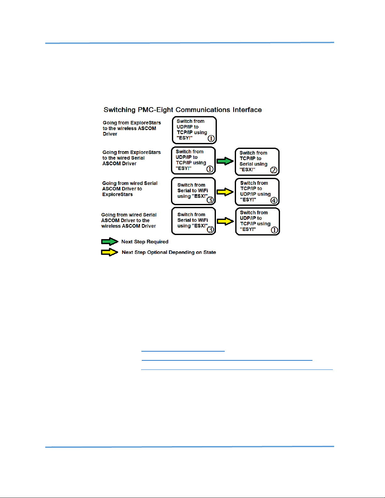
Explore Scientific PMC-Eight™ Controller Programmer’s Reference
DOC-ESPMC8-002 Rev. 1.2 2019 March 07 (Firmware 09T10, 10A01 and above)
Copyright ©2016-2019 Explore Scientific, LLC. ExploreScientificUSA.com +1 (866) 252-3811, 1010 South 48th Street, Springdale, AR 72762
45
WORKFLOW DIAGRAM
Use the Workflow Diagram to identify the procedures to perform for each specific switching
configuration you require. The procedure numbers (circle number) are indicated in each box
below.
REQUIRED ITEMS
NOTE: The software items listed below are FREE and can be downloaded from the links shown
below.
1. PMC-Eight™ Control System Box and Power Supply.
2. Microsoft Windows® PC System with Internet Access.
3. USB type A to mini-USB type B cable.
4. Packet Sender program https://packetsender.com/
5. Putty terminal program https://www.chiark.greenend.org.uk/~sgtatham/putty/
6. Parallax Serial Terminal https://www.parallax.com/downloads/parallax-serial-terminal
APPLICABLE PMC-Eight™ Hardware/Firmware Versions
1. PMC-Eight™ System Controller version 1A-01C or later. (Only used in the iEXOS 100.)
2. PMC-Eight™ System Controller Firmware version 10B01 or later.
Page 47
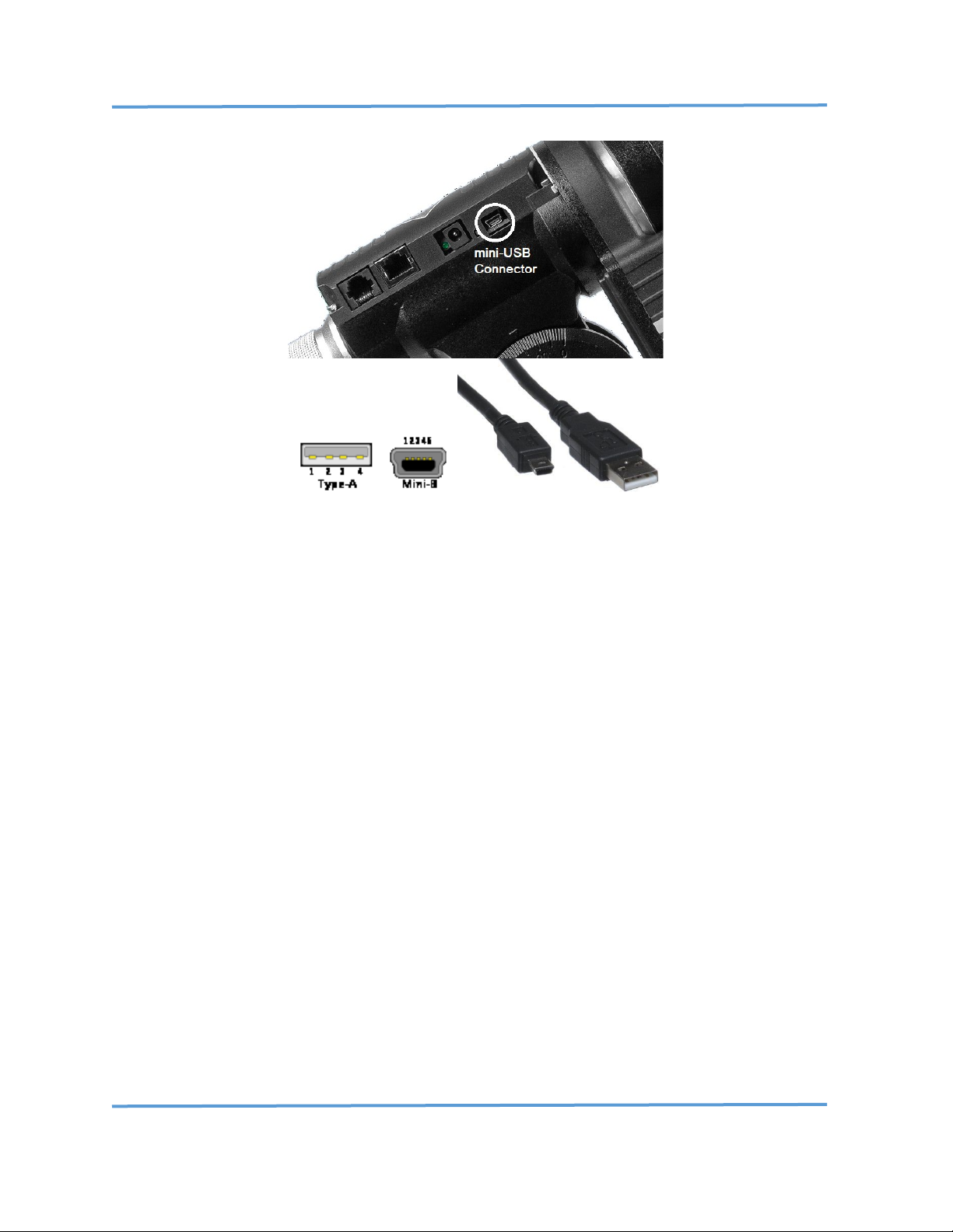
Explore Scientific PMC-Eight™ Controller Programmer’s Reference
DOC-ESPMC8-002 Rev. 1.2 2019 March 07 (Firmware 09T10, 10A01 and above)
Copyright ©2016-2019 Explore Scientific, LLC. ExploreScientificUSA.com +1 (866) 252-3811, 1010 South 48th Street, Springdale, AR 72762
46
SERIAL communications port mini-USB Type B and USB type A connectors and cable.
SETUP PROCEDURE
First, install both programs by following the installation instructions included in the installation.
The TELNET parameters to connect to the PMC-Eight™ for Putty are:
IP ADDRESS: 192.168.47.1
PORT: 54372
The serial port parameters to connect to the PMC-Eight™ for Putty and the Parallax Serial
Terminal are:
BAUD Rate: 115200
Data Bits: 8
Stop Bits: 1
Parity: NONE
Flow Control: NONE
Procedure
Switch from UDP/IP to TCP/IP using the “ESY!” command
NOTE: This procedure assumes that you start with the delivered configuration of the PMC-Eight™
with the WiFi interface enabled.
Page 48

Explore Scientific PMC-Eight™ Controller Programmer’s Reference
DOC-ESPMC8-002 Rev. 1.2 2019 March 07 (Firmware 09T10, 10A01 and above)
Copyright ©2016-2019 Explore Scientific, LLC. ExploreScientificUSA.com +1 (866) 252-3811, 1010 South 48th Street, Springdale, AR 72762
47
1. Launch the program Packet Sender.
2. Power up your iEXOS 100™ mount
3. Switch your computer over to the PMC-Eight-xxxx SSID specific to your controller.
4. Using Packet Sender, configure the following fields as shown in the figure below in the
RED box:
ASCII: ESY!
Address: 192.168.47.1
Port: 54372
Protocol: UDP (pull-down)
5. While watching the RED and GREEN LEDs on the iEXOS 100 mount, press the SEND button
to transmit the “ESY!” command. You should see the GREEN LED flash on.
6. Verify that the request and response are shown in Packet Sender as illustrated in the
figure below in the GREEN box. You should see an “ESY0!” response.
7. You should now be able to connect via TELNET using PUTTY.
Page 49

Explore Scientific PMC-Eight™ Controller Programmer’s Reference
DOC-ESPMC8-002 Rev. 1.2 2019 March 07 (Firmware 09T10, 10A01 and above)
Copyright ©2016-2019 Explore Scientific, LLC. ExploreScientificUSA.com +1 (866) 252-3811, 1010 South 48th Street, Springdale, AR 72762
48
Procedure
Switch from TCP/IP to SERIAL using the “ESX!” command
1. Switch your computer over to the PMC-Eight-xxxx SSID specific to your controller. Using
Putty, TELNET into address 192.168.47.1 port 54372.
NOTE: You will not see any prompt on the terminal screen.
2. Enter "ESX!" on the terminal window, and you should see an "ESX0!" response, which
indicates that the communications interface was switched to the serial port (interface 0).
3. You should now be able to use the SERIAL mini-USB Type B (female) connection with your
mini-USB Type B (male) to USB Type A (male) cable to communicate with the iEXOS 100.
Procedure
Switch from SERIAL to WiFi using the “ESX!” command
NOTE: You can determine the assigned com port number in the following step by using the
windows settings program Device Manager.
1. Using the Parallax Serial Terminal, connect to the assigned com port number with
connection parameters: 115200, N, 8, 1.
2. Once connected, you should see the firmware startup splash screen information scroll on
the screen. (See firmware startup splash screen example at the end of this document.)
3. At the top line, enter "###". You should see "Diagnostic Mode Disabled#".
4. Enter "ESX!", and you should see "ESX1!", which indicates that the interface was switched
to the WiFi port (interface 1).
Procedure
Switch from TCP/IP to UDP/IP using the “ESY!” command
1. Switch your computer over to the PMC-Eight-xxxx SSID specific to your controller.
2. Using Putty, TELNET into address 192.168.47.1 port 54372.
NOTE: You will not see any prompt on the terminal screen.
3. Enter "ESY!", and you should see "ESY1!", which indicates that the interface was switched
to UDP/IP from TCP/IP on WiFi (interface 1).
4. You should now be able to wirelessly use the ExploreStars™ application with the iEXOS
100™.
PMC-Eight™ Firmware Startup Splash Screen
Page 50

Explore Scientific PMC-Eight™ Controller Programmer’s Reference
DOC-ESPMC8-002 Rev. 1.2 2019 March 07 (Firmware 09T10, 10A01 and above)
Copyright ©2016-2019 Explore Scientific, LLC. ExploreScientificUSA.com +1 (866) 252-3811, 1010 South 48th Street, Springdale, AR 72762
49
This is the startup splash screen that you will see when booting up the system while connected
via the SERIAL port with the Parallax Serial Terminal.
-------------------------------------------------------------
------------------------------------------------------------ PPPPPPP MM MM CCCCCCCC 88888
PP PP MMM MMM CC 88 88
PPPPPPP MM M M MM CC XXXXX 888
PP MM M M MM CC 88 88
PP MM MM MM CCCCCCCC 88888
------------------------------------------------------------Copyright 2013-2018 Explore Scientific LLC., Gerald R Hubbell
1010 South 48th Street, Springdale, AR 72762
PMC-Eight Support 1-866-252-3811
http://www.explorescientificusa.com
------------------------------------------------------------Portions of FIRMWARE covered by MIT LICENSE terms
------------------------------------------------------------Explore Scientific PMC-Eight Controller - Startup
Initializing PMC-Eight Model 1A-01C-FW10B1a 10 AUGUST 2018...
CONFORM TEST VERSION - COMMUNICATIONS TIMEOUT DISABLED
------------------------------------------------------------EEPROM Memory Test - Basic
MEM_TEST1:F0F0F0F0
MEM_TEST2:0F0F0F0F
MEM_TEST3:F0F0F0F0
MEM_TEST4:0F0F0F0F
MEM_TEST5:F0F0F0F0
----------------------------------------------------------Command Processor Started
JOC Controller Command Set: Enabled
PMC-Eight Diagnostic Command Set: Enabled
PMC-Eight ES Command Set: Enabled
System Initialized!
------------------------------------------------------------BAUD Rate Value: P0 115200
Assigned SSID: PMC-Eight-280D
Communications Channel - Enabled: P1 Serial
WiFi Protocol - Disabled: P2 UDP/IP
Assigned WiFi Channel Number: 7
ST4 port Sidereal Rate Fraction: P3 40
Unused Value: P4 0
Unused Value: P5 0
Unused Value: P6 0
Unused Value: P7 0
Unused Value: P8 0
Unused Value: P9 0
-------------------------------------------------------------
If you have any issues performing these procedures, or if you have suggestions, comments, or
questions, please contact support@explorescientific.com or call our customer support number
(866)252-3811.
Page 51

Explore Scientific PMC-Eight™ Controller Programmer’s Reference
DOC-ESPMC8-002 Rev. 1.2 2019 March 07 (Firmware 09T10, 10A01 and above)
Copyright ©2016-2019 Explore Scientific, LLC. ExploreScientificUSA.com +1 (866) 252-3811, 1010 South 48th Street, Springdale, AR 72762
50
CUSTOMER NOTE: The procedure provided here is for reference only and is for internal
Explore Scientific Use Only.
CUSTOMERS SHALL NOT HAVE ACCESS TO, NOR POSSESS THE PMC-Eight™
SYSTEM FIRMWARE SOURCE CODE (.SPIN) FILES REFERRED TO IN THE FOLLOWING
PROCEDURE.
ALL PMC-Eight™ SYSTEM FIRMWARE IS EXPLORE SCIENTIFIC, LLC PROPRIETARY
INFORMATION AND CONFIDENTIAL.
Explore Scientific PMC-Eight™ version 2A-006A/B
Autoguider (ST-4) Port Calibration Procedure (Rev 1.3)
Firmware Version 9r4 08162015 AND LATER
2015 August 22
NOTE: This procedure is applicable to all firmware later than version 9r4 08162015. The steps that
refer to a specific version also apply to later versions of the firmware that include AUTOGUIDER
support (Hardware version 2A_006A and 2A_006B). In those steps, load, modify, and compile the
latest version of the firmware available. This procedure also works with OpenGOTO™ application
version 1.1.5.1 OR LATER.
1.0 Discussion
The Autoguider port on the Explore Scientific PMC-Eight™ controller uses a Voltage Controlled
Oscillator (VCO) circuit to convert ST-4 port contact inputs to a unique frequency for that contact
input combination. The circuit uses an SE555 timer chip to create the square wave output that is
measured by the processor firmware and processed into a frequency value. This design was used to
minimize the number of I/O pins used (only one is used, versus four that would be necessary) because
the number available on the propeller chip is very limited in this design.
There is a test point, TP_ST4, available on the PMC-Eight™ controller board to measure the frequency
using a digital multimeter with frequency measurement or an oscilloscope. IT IS IMPORTANT TO
NOTE: this measured value cannot be used for calibration; the following procedure shows how to use
the built in firmware test (command mode) to take the measurements and do the calibration.
The firmware constant AG_TOLERANCE is used to compensate for a small variation in the measured
frequencies over time and is used also as a discriminator, so the measured value is stable and does
not chatter. Normally this value will not change, but it may be necessary in certain cases. The
AG_TOLERANCE is set to +/- 40 Hz.
Page 52

Explore Scientific PMC-Eight™ Controller Programmer’s Reference
DOC-ESPMC8-002 Rev. 1.2 2019 March 07 (Firmware 09T10, 10A01 and above)
Copyright ©2016-2019 Explore Scientific, LLC. ExploreScientificUSA.com +1 (866) 252-3811, 1010 South 48th Street, Springdale, AR 72762
51
The range of frequencies is approximately 2500 Hz to 5600 Hz. This design will be modified in that
the circuit components will be changed to create frequencies from 2500 Hz to 8800 Hz to help
discriminate the contact input and increase the tolerance range so that a common set of frequency
values can be used on the system. This mitigates the need for the custom calibration of the controller
that this procedure is designed to perform. This procedure is also used to perform the initial
calibration of the production sample to apply to all the production level hardware.
2.0 Purpose
The purpose of this procedure is to measure the PMC-Eight™ Autoguider Port frequencies generated
for each contact input condition. These values are used in the firmware to calculate which of the four
contacts are closed and modify the RA and DEC position accordingly to maintain a lock on the desired
object. This procedure describes how to adjust and save the measured values in the firmware and
reprogram the system.
3.0 Equipment Used
3.1 PMC-Eight™ System version 2A-006A controller
3.2 Autoguider Switch Test Box and RJ cable
3.3 Firmware version 9r4 08162015 OR LATER
3.4 Parallax Propeller Editor/Development System (IDE) version 1.3.2
3.5 USB/Serial cable—Programmer Port Connection
3.6 Windows WinBook Tablet with the OpenGOTO™ Ver 1.1.5.1 OR LATER installed.
4.0 Procedure
4.1 VERIFY that all the equipment listed in section 3.0 is available and in working order.
4.2 START the Propeller IDE on the PC.
4.3 CONNECT the PC to the PMC-Eight™ controller Serial Port using the USB/Serial cable.
4.4 CONNECT the RJ cable to the PMC-Eight™ Autoguider Port and the Autoguider Switch Test
Box.
4.5 APPLY power to the PMC-Eight™ controller.
4.6 In the IDE, NAVIGATE to the directory that contains the FIRMWARE version 9r4 08162015.
4.7 ENSURE that the following files are in the directory:
4.7.1 ES_MotionController_9r_4.spin OR LATER
4.7.2 SerialMirror_3.spin
4.7.3 Basic_I2C_Driver.spin
4.7.4 settings.spin
4.8 RIGHT CLICK the file “ES_MotionController_9r_4.spin” OR LATER, and SELECT “Top Object
File”.
4.9 CLICK the file “ES_MotionController_9r_4.spin” OR LATER to load it into the IDE code window.
4.10 In the IDE, CLICK the Run, Identify Hardware… menu items and VERIFY that the following
message displays: Propeller chip version 1 found on COMx. RECORD the COM port identified.
Page 53

Explore Scientific PMC-Eight™ Controller Programmer’s Reference
DOC-ESPMC8-002 Rev. 1.2 2019 March 07 (Firmware 09T10, 10A01 and above)
Copyright ©2016-2019 Explore Scientific, LLC. ExploreScientificUSA.com +1 (866) 252-3811, 1010 South 48th Street, Springdale, AR 72762
52
4.11 In the IDE, SCROLL DOWN to code line number (line numbers are located at the lower left of
the IDE window) 142 to IDENTIFY the AUTOGUIDER constants section. Lines 143–153 list the
FREQUENCIES for each contact combination.
4.12 In the IDE, SCROLL DOWN to line number 308 and IDENTIFY the SP_SELECT value.
4.13 In the IDE, MODIFY the line to read: “SP_SELECT := 0”, this places the firmware in the Terminal
Interface mode.
4.14 In the IDE, CLICK Run, Compile Top, Load EEPROM menu items to compile the code and load
it onto the PMC-Eight™ system.
4.15 In the IDE, CLICK the Run, Parallax Serial Terminal… menu item to start the terminal program.
ENSURE that the baud rate is set to 115,200 and that the COM port is set to the value recorded
in step 4.8.
4.16 On the Terminal program, CLICK the ENABLE button on the lower right.
4.17 PUSH the RESET button on the PMC-Eight™ and VERIFY that the following messages appear
in the OUTPUT window:
Explore Scientific PMC-Eight Controller - Startup
Copyright 2013-2014 Explore Scientific, Gerald R Hubbell
Portions of FIRMWARE covered by MIT LICENSE terms
Initializing PMC-Eight Model 2A-06B-FW9R4 16 August 2015...
EEPROM Memory Test - Basic
MEM_TEST1:F0F0F0F0
MEM_TEST2:0F0F0F0F
MEM_TEST3:F0F0F0F0
MEM_TEST4:0F0F0F0F
MEM_TEST5:F0F0F0F0
JOC Controller Command Set: Enabled
PMC-Eight Simplified Command Set: Enabled
032032Command Processor Started
System Initialized!
4.18 In the Terminal program, ENTER “$$$” into the INPUT window at the top of the program.
CLICK the PAUSE button at the bottom of the Terminal program.
4.19 SCROLL up the OUTPUT window and VERIFY that the following messages appear in the
OUTPUT window:
ASCII Command Mode Started
Watch Dog Timer STOPPED
2618 1
2618 1
2618 1
2618 1
...
4.20 CLICK the RESUME button at the bottom of the Terminal Program to start the scrolling live
view of the Autoguider Frequencies. There are two values shown, the Frequency value and
the calculated, enumerated contact combination value. For each button push, the values will
change accordingly.
Page 54

Explore Scientific PMC-Eight™ Controller Programmer’s Reference
DOC-ESPMC8-002 Rev. 1.2 2019 March 07 (Firmware 09T10, 10A01 and above)
Copyright ©2016-2019 Explore Scientific, LLC. ExploreScientificUSA.com +1 (866) 252-3811, 1010 South 48th Street, Springdale, AR 72762
53
NOTE: The following step is only a quick functional test performed prior to performing the Frequency
measurements and calibration. It is important that this test is successful prior to measurement and
verifies that the hardware is operating correctly.
4.21 On the Autoguider Switch Test Box, PRESS each of the Test Box buttons and VERIFY that the
value changes accordingly.
Fig. 1 Autoguider Switch Test Box
NOTE: In the following step, the Autoguider Switch Test Box when handled will cause the frequencies
to vary. It is important to estimate and record a middle value in the range of values displayed. The
AG_TOLERANCE value is used to compensate for this variation in values and should not be an issue.
4.22 FOR EACH of the following buttons (refer to Fig. 1) RECORD a representative sample of the
displayed Frequencies. PRESS the PAUSE and RESUME button on the Terminal program AS
NECESSARY to view each value and record the value. NOTE that the OPEN position is NO BUTTONS
PUSHED.
4.22.1 OPEN ________________
4.22.2 NORTH ________________
4.22.3 EAST ________________
4.22.4 SOUTH ________________
4.22.5 WEST ________________
4.22.6 NORTH AND EAST ________________
4.22.7 NORTH AND WEST ________________
4.22.8 SOUTH AND EAST ________________
4.22.9 SOUTH AND WEST ________________
4.23 USING the values recorded in step 4.22, in the IDE, SCROLL to line number 142 and MODIFY
each of the lines for each button combinations.
Page 55

Explore Scientific PMC-Eight™ Controller Programmer’s Reference
DOC-ESPMC8-002 Rev. 1.2 2019 March 07 (Firmware 09T10, 10A01 and above)
Copyright ©2016-2019 Explore Scientific, LLC. ExploreScientificUSA.com +1 (866) 252-3811, 1010 South 48th Street, Springdale, AR 72762
54
4.24 REPEAT Step 4.22 only to VERIFY that the enumerated contact combination displays a value
other than 0 (zero). IF THIS IS NOT SUCCESSFUL, REPEAT steps 4.22–4.23 and RECORD new
values for those button combinations that display a 0 (zero) for the enumerated button
combination.
4.24 In the IDE, MODIFY the line identified in step 4.12 to: “SP_SELECT := 1”; this places the
firmware in the Wireless Interface mode.
4.25 In the IDE, CLICK Run, Compile Top, Load EEPROM menu items to compile the code and load
it onto the PMC-Eight™ system.
4.26 On the IDE, CLICK the File, Save, menu item to save the values in the Firmware file.
4.27 RESET the PMC-Eight™ by pressing the RESET button to restart the system.
4.28 USING the OpenGOTO™ application on the Windows tablet, CONNECT to the controller, and
with the program in TRACK MODE as indicated by the “Tr” icon, perform the following step.
4.29 PUSH each button combination on the Autoguider Switch Test Box and VERIFY that the RA
and DEC positions change as desired.
Page 56

Explore Scientific PMC-Eight™ Controller Programmer’s Reference
DOC-ESPMC8-002 Rev. 1.2 2019 March 07 (Firmware 09T10, 10A01 and above)
Copyright ©2016-2019 Explore Scientific, LLC. ExploreScientificUSA.com +1 (866) 252-3811, 1010 South 48th Street, Springdale, AR 72762
55
ASCOM Platform Conformance Test Report – Explore Scientific PMC-Eight™ ASCOM Driver
Conform Report Hash (V1): BAC544670181C9C373F29317D03DBEA7D6F48 D4A593FA875C8B97DF2C366C89905F266ED70A96ADD71E012F8E4730E 90A055AD3001489F6BF46D0842809FC410
ConformanceCheck ASCOM Device Conformance Checker Version 6.2.5 9.0, Build time: 1/9/2017 8:44:30 AM
ConformanceCheck Running on: ASCOM Platform 6.4 SP1 6.4.1.2695
ConformanceCheck Driver ProgID: ASCOM.ES_PMC8.Telescope
Error handling
Error number for "Not Implemented" is: 80040400
Error number for "Invalid Value 1" is: 80040401
Error number for "Invalid Value 2" is: 80040405
Error number for "Value Not Set 1" is: 80040402
Error number for "Value Not Set 2" is: 80040403
Error messages will be interpreted to infer state.
14:43:54.231 Driver Access Checks OK
14:43:54.942 AccessChecks OK Success fully created driver using late binding
14:43:55.145 AccessChecks OK Successfully connected using late binding
14:43:55.154 AccessChecks INFO The driver is a .NET object
14:43:55.163 AccessChecks INFO The Ass emblyQualifiedName is: ASCOM.ES_PMC8.Telescope, ASCOM.ES_PMC8.Telescope, Version=6.0.0.1,
Culture=n
14:43:55.174 AccessChecks INFO The dri ver implements interface: ASCOM.DeviceInterface.ITelescop eV3
14:43:56.069 AccessChecks INFO Device does not expose interface ITelescopeV2
14:43:56.836 AccessChecks INFO Device exposes interface ITelescopeV3
14:43:58.310 AccessChecks OK Success fully created driver using driver access toolkit
14:43:58.387 AccessChecks OK Successfully connected using driver access toolkit
Conform is using ASCOM.DriverAccess.Telescope to get a Telescope object
14:43:59.867 ConformanceCheck OK Driver instance created successfully
14:43:59.986 ConformanceCheck OK Connect ed OK
Common Driver Methods
14:44:00.049 InterfaceVersion OK 3
14:44:00.083 Connected OK True
14:44:00.116 Description OK ES_PMC8 Telescope
14:44:00.150 DriverInfo OK Explore Scientific PMC-Eight Mount Controller ASCOM Driver. Developed by GRHubbell. Contact Explore
Scientific at www.explorescientificusa.com . Version: 6.0
14:44:00.185 DriverVersion OK 6.0
14:44:00.227 Name OK Explore Scientific PMC-Eight ASCOM Driver
14:44:00.262 CommandString INFO Conform cannot test the CommandString method
14:44:00.271 CommandBlind INFO Conform cannot test the CommandBlind method
14:44:00.280 CommandBool INFO Conform cannot test the CommandBool method
14:44:00.289 Action INFO Conform cannot test the Action method
14:44:00.299 SupportedActions OK CanPark
14:44:00.311 SupportedActions OK CanSetTracking
14:44:00.328 SupportedActions OK CanSlew
14:44:00.337 SupportedActions OK CanSlewAltAz
14:44:00.348 SupportedActions OK CanSlew Async
14:44:00.360 SupportedActions OK CanSlewAltAzAsync
14:44:00.369 SupportedActions OK CanSync
14:44:00.381 SupportedActions OK CanSync AltAz
14:44:00.392 SupportedActions OK CanUnpa rk
14:44:00.404 SupportedActions OK CanMove Axis
14:44:00.414 SupportedActions OK DoesRefraction
14:44:00.424 SupportedActions OK Can...
Can Properties
14:44:00.503 CanFindHome OK True
14:44:00.514 CanPark OK True
14:44:00.525 CanPulseGuide OK True
14:44:00.536 CanSetDeclinationRate OK True
14:44:00.547 CanSetGuideRates OK True
14:44:00.559 CanSetPark OK True
14:44:00.571 CanSetPierSide OK True
14:44:00.582 CanSetRightAscensionRate OK True
14:44:00.595 CanSetTracking OK True
14:44:00.607 CanSlew OK True
14:44:00.618 CanSlewltAz OK True
14:44:00.631 CanSlewAltAzAsync OK True
14:44:00.651 CanSlewAsync OK True
14:44:00.665 CanSync OK True
14:44:00.678 CanSyncAltAz OK True
14:44:00.691 CanUnPark OK True
Pre-run Checks
14:44:00.750 Mount Safety INFO Scope i s parked, so it has been unparked for testing
14:44:00.817 Mount Safety INFO Scope tracking has been enabled
14:44:00.860 TimeCheck INFO PC Time Zone: Eastern Standard Time, offset 5 hours.
14:44:00.873 TimeCheck INFO PC UTCD ate: 07-Jan-2019 19:44:00.873
14:44:00.889 TimeCheck INFO Mount U TCDate: 07-Jan-2019 19:44:00.889
Properties
14:44:00.969 AlignmentMode OK algGerm anPolar
14:44:01.056 Altitude OK 38.33
14:44:01.095 ApertureArea OK 0.00817
14:44:01.131 ApertureDiameter OK 0.102
14:44:01.170 AtHome OK False
14:44:01.207 AtPark OK False
14:44:01.283 Azimuth OK 0.00
14:44:01.330 Declination OK 90:00: 00.00
14:44:01.371 DeclinationRate Read OK 0.00
14:44:01.425 DeclinationRate Write OK 0.00
14:44:01.462 DoesRefraction Read OK True
14:44:01.502 DoesRefraction Write OK Can set DoesRefraction to False
14:44:01.543 EquatorialSystem OK equLocalTopocentric
14:44:01.583 FocalLength OK 0.714
14:44:01.620 GuideRateDeclination Read OK 0.00
14:44:01.633 GuideRateDeclination Write OK Can wri te Declination Guide Rate OK
14:44:01.671 GuideRateRightAscension Read OK 0.00
14:44:01.690 GuideRateRightAscension Write OK Can set RightAscension Guide OK
14:44:01.728 IsPulseGuideing OK False
14:44:01.794 RightAscension OK 03:41:30.65
14:44:01.832 RightAscensionRate Read OK 15.00
14:44:01.873 RightAscensionRate Write OK 15.00
14:44:01.909 SiteElevation Read OK 100
14:44:01.966 SiteElevation Write OK Invalid Value exception generated as expected on set site elevation < -300m
14:44:01.984 SiteElevation Write OK Invalid Value exception generated as expected on set site elevat ion > 10,000m
14:44:02.019 SiteElevation Write OK Legal value 100m written successfully
14:44:02.055 SiteLatitude Read OK 38:19: 58.80
14:44:02.095 SiteLatitude Write OK Invalid Value exception generated as expected on set site latit ude < -90 degrees
14:44:02.126 SiteLatitude Write OK Invalid Value exception generated as expected on set site latitude > 90 degrees
14:44:02.158 SiteLatitude Write OK Legal v alue 38:19:58.80 degrees written successfully
14:44:02.200 SiteLongitude Read OK -77:42:38.16
14:44:02.237 SiteLongitude Write OK Invalid Value exception generated as expected on set site longit ude < -180 degrees
14:44:02.265 SiteLongitude Write OK Invalid Value exception generated as expected on set site longitude > 180 degrees
14:44:02.282 SiteLongitude Write OK Legal v alue -77:42:38.16 degrees written successfully
14:44:02.400 Slewing OK False
14:44:02.448 SlewSettleTime Read OK Optional member threw a PropertyNotImplementedException exception.
14:44:02.497 SlewSettleTime Write OK Optiona l member threw a PropertyNotImplementedException excepti on.
14:44:02.516 SlewSettleTime Write OK Optional member threw a PropertyNotImplementedException exception.
14:44:02.577 SideOfPier Read OK pierWes t
14:44:02.591 SiderealTime OK 21:41:3 2.41
Page 57

Explore Scientific PMC-Eight™ Controller Programmer’s Reference
DOC-ESPMC8-002 Rev. 1.2 2019 March 07 (Firmware 09T10, 10A01 and above)
Copyright ©2016-2019 Explore Scientific, LLC. ExploreScientificUSA.com +1 (866) 252-3811, 1010 South 48th Street, Springdale, AR 72762
56
14:44:02.604 SiderealTime OK Scope and ASCOM sidereal times agree to better than 1 second, Scope: 21:41:32.41, ASCOM:
21:41:32.41
14:44:02.643 TargetDeclination Read OK .NET No t Set exception generated on read before write
14:44:02.695 TargetDeclination Write OK Invalid Value exception generated as expected on set TargetDeclination < -90 degrees
14:44:02.718 TargetDeclination Write OK Invalid Value exception generated as expected on set TargetDeclination < -90 degrees
14:44:02.752 TargetDeclination Write OK Legal v alue 01:00:00.00 DD:MM:SS written successfully
14:44:02.791 TargetRightAscension Read OK .NET No t Set exception generated on read before write
14:44:02.832 TargetRightAscension Write OK Invalid Value exception generated as expected on set TargetRightAscension < 0 hours
14:44:02.860 TargetRightAscension Write OK Invalid Value exception generated as expected on set TargetRightAscension > 24 hours
14:44:02.890 TargetRightAscension Write OK Legal v alue 17:41:32.71 HH:MM:SS written successfully
14:44:02.928 Tracking Read OK True
14:44:04.022 Tracking Write OK False
14:44:05.135 TrackingRates Found drive rate: driveSidereal
14:44:05.148 TrackingRates Found d rive rate: driveLunar
14:44:05.162 TrackingRates Found drive rate: driveSolar
14:44:05.178 TrackingRates Found drive rate: driveKing
14:44:05.192 TrackingRates OK Drive r ates read OK
14:44:05.229 TrackingRate Read OK driveSidereal
14:44:05.279 TrackingRate Write OK Successfully set drive rate: driveSidereal
14:44:05.327 TrackingRate Write OK Success fully set drive rate: driveLunar
14:44:05.390 TrackingRate Write OK Successfully set drive rate: driveSolar
14:44:05.455 TrackingRate Write OK Successfully set drive rate: driveKing
14:44:05.510 UTCDate Read OK 07-Jan-2019 19:4 4:05.510
14:44:05.527 UTCDate Write OK Optional member threw a PropertyNotImplementedException exception.
Methods
14:44:05.639 CanMoveAxis:Primary OK CanMove Axis:Primary True
14:44:05.681 CanMoveAxis:Secondary OK CanMoveAxis:Secondary True
14:44:05.721 CanMoveAxis:Tertiary OK CanMoveAxis:Tertiary False
14:44:07.728 Park OK Success
14:44:07.741 Park OK Success if already parked
14:44:07.769 Park:AbortSlew OK AbortSl ew did raise an exception when Parked as required
14:44:07.839 Park:FindHome OK FindHom e did raise an exception when Parked as required
14:44:07.884 Park:MoveAxis Primary OK MoveAxis Primary did raise an exception when Parked as required
14:44:07.938 Park:MoveAxis Secondary OK MoveAxi s Secondary did raise an exception when Parked as require d
14:44:07.987 Park:PulseGuide OK PulseGuide did raise an exception when Parked as required
14:44:08.044 Park:SlewToCoordinates OK SlewToC oordinates did raise an exception when Parked as required
14:44:08.091 Park:SlewToCoordinatesAsync OK SlewToC oordinatesAsync did raise an exception when Parked as req uired
14:44:08.137 Park:SlewToTarget OK SlewToTarget did raise an exception when Parked as required
14:44:08.187 Park:SlewToTargetAsync OK SlewToT argetAsync did raise an exception when Parked as required
14:44:08.246 Park:SyncToCoordinates OK SyncToCoordinates did raise an exception when Parked as required
14:44:08.291 Park:SyncToTarget OK SyncToT arget did raise an exception when Parked as required
14:44:08.655 UnPark OK Success
14:44:08.690 UnPark OK Success if already unparked
14:44:08.796 AbortSlew OK AbortSlew Ok when not slewing
14:44:08.866 AxisRate:Primary OK Axis ra te minimum: 2.5 Axis rate maximum: 2.5
14:44:08.880 AxisRate:Primary OK Axis ra te minimum: 0.2083333 Axis rate maximum: 0.2083333
14:44:08.896 AxisRate:Primary OK Axis ra te minimum: 0.0208333 Axis rate maximum: 0.020833 3
14:44:08.911 AxisRate:Primary OK Axis ra te minimum: 0.0025 Axis rate maximum: 0.0025
14:44:08.929 AxisRate:Primary OK Axis rate minimum: 0 Axis rate maximum: 0
14:44:08.945 AxisRate:Primary OK No overlapping axis rates found
14:44:08.961 AxisRate:Primary OK No dupl cate axis rates found
14:44:08.981 AxisRate:Secondary OK Axis ra te minimum: 2.5 Axis rate maximum: 2.5
14:44:09.001 AxisRate:Secondary OK Axis rate minimum: 0.2083333 Axis rate maximum: 0.2083333
14:44:09.017 AxisRate:Secondary OK Axis rate minimum: 0.0208333 Axis rate maximum: 0.0208333
14:44:09.033 AxisRate:Secondary OK Axis rate minimum: 0.0025 Axis rate maximum: 0.0025
14:44:09.049 AxisRate:Secondary OK Axis ra te minimum: 0 Axis rate maximum: 0
14:44:09.064 AxisRate:Secondary OK No over lapping axis rates found
14:44:09.080 AxisRate:Secondary OK No duplcate axis rates found
14:44:09.097 AxisRate:Tertiary OK Empty axis rate returned
14:44:09.735 FindHome OK Found h ome OK.
14:44:09.820 MoveAxis Primary OK Can successfully set a movement rate of zero
14:44:09.874 MoveAxis Primary OK Exception correctly generated when moveaxis set below lowest rate (-3.5)
14:44:09.949 MoveAxis Primary OK Excepti on correctly generated when moveaxis set above highest ra te (3.5)
14:44:14.185 MoveAxis Primary OK Successfully moved axis at minimum rate: 0
14:44:18.664 MoveAxis Primary OK Success fully moved axis at maximum rate: 2.5
14:44:22.966 MoveAxis Primary OK Trackin g state correctly retained for both tracking states
14:44:23.045 MoveAxis Secondary OK Can suc cessfully set a movement rate of zero
14:44:23.078 MoveAxis Secondary OK Exception correctly generated when moveaxis set below lowest rate (-3.5)
14:44:23.157 MoveAxis Secondary OK Exception correctly generated when moveaxis set above highest rate (3.5)
14:44:27.394 MoveAxis Secondary OK Successfully moved axis at minimum rate: 0
14:44:31.982 MoveAxis Secondary OK Successfully moved axis at maximum rate: 2.5
14:44:36.285 MoveAxis Secondary OK Tracking state correctly retained for both tracking states
14:44:36.352 MoveAxis Tertiary OK Receive d an invalid value exception
14:44:38.474 PulseGuide OK Synchro nous pulseguide found OK
14:45:17.634 SlewToCoordinates INFO Slewed within 53.6 arc seconds of expected RA: 20:42:08.49, actual RA: 20:42:04.92
14:45:17.667 SlewToCoordinates OK Slewed OK. DEC: 01:00:00.00
14:45:17.723 SlewToCoordinates (Bad L) OK Correct ly rejected bad RA coordinate: -01:00:00.00
14:45:17.749 SlewToCoordinates (Bad L) OK Correct ly rejected bad Dec coordinate: -100:00:00.00
14:45:17.818 SlewToCoordinates (Bad H) OK Correctly rejected bad RA coordinate: 25:00:00.00
14:45:17.842 SlewToCoordinates (Bad H) OK Correctly reject ed bad Dec coordinate: 100:00:00.00
14:45:26.653 SlewToCoordinatesAsync INFO Slewed within 23.3 arc seconds of expected RA: 19:42:47.97, actual RA: 19:42:49.52
14:45:26.685 SlewToCoordinatesAsync OK Slewed OK. DEC: 02:00:00.00
14:45:26.728 SlewToCoordinatesAsync (Bad L) OK Correct ly rejected bad RA coordinate: -01:00:00.00
14:45:26.751 SlewToCoordinatesAsync (Bad L) OK Correctly rejected bad Dec coordinate: -100:00:00.00
14:45:26.815 SlewToCoordinatesAsync (Bad H) OK Correct ly rejected bad RA coordinate: 25:00:00.00
14:45:26.835 SlewToCoordinatesAsync (Bad H) OK Correct ly rejected bad Dec coordinate: 100:00:00.00
14:45:35.545 SlewToTarget INFO Slewed within 21.3 arc seconds of expected RA: 18:42:56.98, actual RA: 18:42:58.39
14:45:35.576 SlewToTarget OK Slewed OK. DEC: 03:00:00.00
14:45:35.619 SlewToTarget (Bad L) OK Telescope.TargetRA correctly rejected bad RA coordinate: -01:00:00.00
14:45:35.643 SlewToTarget (Bad L) OK Telesco pe.TargetDeclination correctly rejected bad Dec coord inate: -100:00:00.00
14:45:35.719 SlewToTarget (Bad H) OK Telescope.TargetRA correctly rejected bad RA coordinate: 25:00:00.00
14:45:35.752 SlewToTarget (Bad H) OK Telesco pe.TargetDeclination correctly rejected bad Dec coordinate: 100:00:00.00
14:45:44.547 SlewToTargetAsync INFO Slewed within 21.8 arc seconds of expected RA: 17:43:05.92, actual RA: 17:43:07.38
14:45:44.578 SlewToTargetAsync OK Slewed OK. DEC: 04:00:00.00
14:45:44.625 SlewToTargetAsync (Bad L) OK Telescope.TargetRA correctly rejected bad RA coordinate: -01:00:00.00
14:45:44.659 SlewToTargetAsync (Bad L) OK Telesco pe.TargetDeclination correctly rejected bad Dec coordinat e: -100:00:00.00
14:45:44.732 SlewToTargetAsync (Bad H) OK Telesco pe.TargetRA correctly rejected bad RA coordinate: 25:00:0 0.00
14:45:44.751 SlewToTargetAsync (Bad H) OK Telesco pe.TargetDeclination correctly rejected bad Dec coordinat e: 100:00:00.00
14:45:44.817 DestinationSideOfPier OK DestinationSideOfPier is different on either side of the meridian
14:46:57.016 SlewToAltAz OK Slewed to target Azimuth OK: 150:00:00.00
14:46:57.079 SlewToAltAz OK Slewed to target Altitude OK: 50:00:00.00
14:46:57.126 SlewToAltAz (Bad L) OK Correct ly rejected bad Altitude coordinate: -100:00:00.00
14:46:57.148 SlewToAltAz (Bad L) OK Correctly rejected bad Azimuth coordinate: -10:00:00.00
14:46:57.211 SlewToAltAz (Bad H) OK Correctly rejected bad Altitude coordinate: 100:00:00.00
14:46:57.234 SlewToAltAz (Bad H) OK Correct ly rejected bad Azimuth coordinate: 370:00:00.00
14:47:02.564 SlewToAltAzAsync OK Slewed to target Azimuth OK: 155:00:00.00
14:47:02.629 SlewToAltAzAsync OK Slewed to target Altitude OK: 55:00:00.00
14:47:02.688 SlewToAltAzAsync (Bad L) OK Correctly rejected bad Altitude coordinate: -100:00:00.00
14:47:02.715 SlewToAltAzAsync (Bad L) OK Correct ly rejected bad Azimuth coordinate: -10:00:00.00
14:47:02.785 SlewToAltAzAsync (Bad H) OK Correct ly rejected bad Altitude coordinate: 100:00:00.00
14:47:02.815 SlewToAltAzAsync (Bad H) OK Correctly rejected bad Azimuth coordinate: 370:00:00.00
14:48:07.372 SyncToCoordinates INFO Slewed to start position within 967.4 arc seconds of expected RA: 18:44:33.23, actual RA:
18:45:37.72
14:48:07.405 SyncToCoordinates OK Slewed to start position OK. DEC: 19:09:59.40
14:48:07.533 SyncToCoordinates OK Synced to sync position OK. RA: 18:40:33.23
14:48:07.565 SyncToCoordinates OK Synced to sync position OK. DEC: 18:09:59.40
14:48:13.049 SyncToCoordinates INFO Slewed back to start position within 57.5 arc seconds of expecte d RA: 18:44:33.23, actual RA:
18:44:37.06
14:48:13.082 SyncToCoordinates OK Slewed back to start position OK. DEC: 19:09:59.40
14:48:13.209 SyncToCoordinates OK Synced to reversed sync position OK. RA: 18:48:33.23
14:48:13.241 SyncToCoordinates OK Synced to reversed sync position OK. DEC: 20:09:59.40
14:48:18.678 SyncToCoordinates INFO Slewed back to start position within 56.8 arc seconds of expecte d RA: 18:44:33.23, actual RA:
18:44:37.02
14:48:18.710 SyncToCoordinates OK Slewed back to start position OK. DEC: 19:09:59.40
Page 58

Explore Scientific PMC-Eight™ Controller Programmer’s Reference
DOC-ESPMC8-002 Rev. 1.2 2019 March 07 (Firmware 09T10, 10A01 and above)
Copyright ©2016-2019 Explore Scientific, LLC. ExploreScientificUSA.com +1 (866) 252-3811, 1010 South 48th Street, Springdale, AR 72762
57
14:48:18.753 SyncToCoordinates (Bad L) OK Correct ly rejected bad RA coordinate: -01:00:00.00
14:48:18.775 SyncToCoordinates (Bad L) OK Correctly rejected bad Dec coordinate: -100:00:00.00
14:48:18.858 SyncToCoordinates (Bad H) OK Correct ly rejected bad RA coordinate: 25:00:00.00
14:48:18.881 SyncToCoordinates (Bad H) OK Correct ly rejected bad Dec coordinate: 100:00:00.00
14:48:24.547 SyncToTarget INFO Slewed to start position within 48.5 arc seconds of expected RA: 18:45:49.50, actual RA:
18:45:52.74
14:48:24.578 SyncToTarget OK Slewed to start position OK. DEC: 19:09:59.40
14:48:24.706 SyncToTarget OK Synced to sync position OK. RA: 18:41:49.50
14:48:24.739 SyncToTarget OK Synced to sync position OK. DEC: 18:09:59.40
14:48:30.206 SyncToTarget INFO Slewed back to start position within 56.7 arc seconds of expected RA: 18:45:49.50, actual RA:
18:45:53.29
14:48:30.239 SyncToTarget OK Slewed back to start position OK. DEC: 19:09:59.40
14:48:30.368 SyncToTarget OK Synced to reversed sync position OK. RA: 18:49:49.50
14:48:30.400 SyncToTarget OK Synced to reversed sync position OK. DEC: 20:09:59.40
14:48:35.853 SyncToTarget INFO Slewed back to start position within 56.6 arc seconds of expected RA: 18:45:49.50, actual RA:
18:45:53.28
14:48:35.885 SyncToTarget OK Slewed back to start position OK. DEC: 19:09:59.40
14:48:35.929 SyncToTarget (Bad L) OK Telescope.TargetRA correctly rejected bad RA coordinate: -01:00:00.00
14:48:35.956 SyncToTarget (Bad L) OK Telesco pe.TargetDeclination correctly rejected bad Dec coordinat e: -100:00:00.00
14:48:36.031 SyncToTarget (Bad H) OK Telesco pe.TargetRA correctly rejected bad RA coordinate: 25:00:0 0.00
14:48:36.062 SyncToTarget (Bad H) OK Telesco pe.TargetDeclination correctly rejected bad Dec coordinat e: 100:00:00.00
14:48:36.412 SyncToAltAz OK Synced Altitude OK
14:48:36.435 SyncToAltAz OK Synced Azimuth OK
14:48:36.478 SyncToAltAz (Bad L) OK Correct ly rejected bad Altitude coordinate: -100:00:00.00
14:48:36.501 SyncToAltAz (Bad L) OK Correct ly rejected bad Azimuth coordinate: -10:00:00.00
14:48:36.568 SyncToAltAz (Bad H) OK Correct ly rejected bad Altitude coordinate: 100:00:00.00
14:48:36.592 SyncToAltAz (Bad H) OK Correctly rejected bad Azimuth coordinate: 370:00:00.00
SideOfPier Model Tests
14:50:01.919 SideOfPier Write INFO This te st will now wait for 7 minutes while the mount tracks thr ough the Meridian
14:58:21.129 SideOfPier Write OK Success fully flipped pierWest to pierEast
15:04:55.028 SideofPier OK Reports the pointing state of the mount as expected
15:04:55.045 SideofPier INFO Reported SideofPier at HA -9, +9: WE
15:04:55.062 SideofPier INFO Reported SideofPier at HA -3, +3: WE
15:04:55.082 SideofPier OK pierWes t is returned when the mount is observing at an hour an gle between -6.0 and 0.0
15:04:55.107 SideofPier OK pierEas t is returned when the mount is observing at an hour angl e between 0.0 and +6.0
15:04:55.123 DestinationSideofPier OK Reports the pointing state of the mount as expected
15:04:55.141 DestinationSideofPier OK pierWes t is returned when the mount will observe at an hour angle between -6.0 and 0.0
15:04:55.157 DestinationSideofPier OK pierEas t is returned when the mount will observe at an hour angl e between 0.0 and +6.0
15:04:55.174 DestinationSideofPier INFO Reported DesintationSideofPier at HA -9, +9: WE
15:04:55.192 DestinationSideofPier INFO Reporte d DesintationSideofPier at HA -3, +3: WE
Performance
Transactions per second: <1=Rather low, 1-2=OK, 2-10=Good, >10=Rather high
15:05:00.313 Performance: Altitude INFO Transac tion rate: 20.6 per second
15:05:05.399 Performance: AtHome INFO Transaction rate: 20.6 per second
15:05:10.437 Performance: AtPark INFO Transac tion rate: 18160.8 per second
15:05:15.522 Performance: Azimuth INFO Transac tion rate: 20.6 per second
15:05:20.572 Performance: Declination INFO Transaction rate: 61.7 per second
15:05:25.614 Performance: IsPulseGuiding INFO Transac tion rate: 17398.0 per second
15:05:30.677 Performance: RightAscension INFO Transac tion rate: 30.9 per second
15:05:35.731 Performance: SideOfPier INFO Transac tion rate: 61.8 per second
15:05:40.773 Performance: SiderealTime INFO Transaction rate: 14775.1 per second
15:05:45.821 Performance: Slewing INFO Transac tion rate: 30.9 per second
15:05:50.862 Performance: UTCDate INFO Transac tion rate: 16735.3 per second
Post-run Checks
15:05:50.970 Mount Safety OK Tracking stopped to protect your mount.
Conformance test complete
No errors, warnings or issues found: your driver passes ASCOM v alidation!!
Driver Hash Value: 8A91BA639244CEF66FC46E4C203B24E77C9DB5519A66 C3F40AAF1CF9E62720F7BAA25BA03CB95B8B9AAF2E8F1D40359C507F2DB3FE1B6413D979BFD8868F3623
Page 59

Explore Scientific PMC-Eight™ Controller Programmer’s Reference
DOC-ESPMC8-002 Rev. 1.2 2019 March 07 (Firmware 09T10, 10A01 and above)
Copyright ©2016-2019 Explore Scientific, LLC. ExploreScientificUSA.com +1 (866) 252-3811, 1010 South 48th Street, Springdale, AR 72762
58
 Loading...