

Explore Scientific FirstLight series, Explore FirstLight 8"" f/6 Dobsonian, Explore FirstLight 10"" f/5 Dobsonian Instruction Manual
Page 1
Explore FirstLight 8" f/6 Dobsonian (FL-DOB0806-01)
Explore FirstLight 10" f/5 Dobsonian (FL-DOB1005-01)
A Dobsonian telescope is designed to capture copious amounts of lights, making it an ideal workhorse for deep-sky
enthusiasts and a great instrument for getting highly detailed views of our planetary neighbors. Although the size of
these telescope models can appear daunting, they can be broken down and transported easily even in small cars and
reassembled within minutes. The FirstLight series includes two Dobsonian models (8” and 10”). Each comes with a 2.5”
Hex focuser, a red dot viewfinder and a 25mm SuperPlossl eyepiece. As an added benefit, each package also includes
an adapter that allows you to use your own smart device to easily capture and share the beauty unfolding in your
eyepiece. With Firstlight, the only thing you need to provide is a desire to discover!
Instruction Manual
Page 2

- 2 -
SUN WARNING
DO NOT use this telescope or any accompanying
finder scope to look at or near the Sun! Even
momentary visual contact with the Sun’s light rays
can instantly cause irreversible damage to your
eye(s). Eye damage can be painless, so there is no
warning to the observer that damage has occurred
until it is too late.
Take extra care when using the telescope or a finder
scope during daylight hours, and do not point either
at or near the Sun. Do not look through either when
you are moving the instruments during the daytime.
Never allow anyone to use the telescope or a
finder scope during the daytime without warning
them of the hazards of aiming either at or near the
Sun. Make sure that they are adequately trained
on the use of these instruments before allowing
them to start observing. Children should always
have informed and trained adult supervision while
observing.
PROPER CARE WARNING
Your telescope is a precision optical device and
keeping the optics free of dust and dirt is crucial for
optimal performance. However, the use of improper
cleaning techniques, tools and/or solutions can
cause irreparable damage to your telescope.
In terms of solutions, use distilled water and/or
an optical glass cleaner that can be found at most
camera stores.
Only use pure cotton swabs/balls or white,
unscented, lotion-free tissues for wiping down
optics after you have removed as many particles as
possible with forced air or a photographic-grade
camel hair brush. DO NOT use optical lens cleaning
tissues as many contain fiberglass particles that can
be abrasive.
GENERAL WARNINGS:
• Children should only use this device under adult
supervision.
• Keep all packing materials (plastic bags, etc) out of
the reach of children. These materials present a risk
of SUFFOCATION or CHOKING!
• Do not allow direct sunlight to pass through the
lenses onto an object. The concentration of light
rays could cause burns or start a fire.
• Do not disassemble this device. In the event of
a defect, please contact the Customer Service
Department.
• Do not expose this device to temperatures
exceeding 60°C (140°F).
• Battery guidelines: The red dot viewfinder contains
electronic components that are powered by
batteries. Batteries should be kept out of children’s
reach. When inserting batteries, please ensure the
polarity is correct. Insert the batteries according to
the displayed +/- information. Never mix old and
new batteries. Replace all batteries at the same
time. Never mix alkaline, standard carbon-zinc and
rechargeable nickel-cadmium batteries. Never
short circuit the device or batteries or throw either
into a fire. Leaking or damaged batteries can cause
injury if they come into contact with the skin. If you
need to handle such batteries, please wear suitable
safety gloves. Remove batteries from the product
before extended storage to prevent leaking. Do not
immerse the battery compartment in water.
!
General Safety Information
Page 3
- 3 -
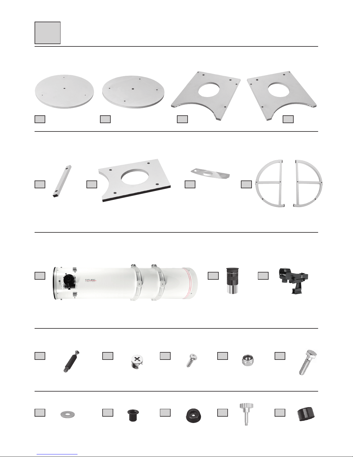
A DC
FE
B
G H
I J K
10x
L
10x
M
5x
N
1x
O
1x
P
2x
Q
2x
R
Fig. 1
3x
S
4x
T
U
Package Contents
I
Page 4
- 4 -
Parts Overview
II
Fig. 2 Inset A
Inset B
1
3
5
4
2
6
7
8
9
10 11
18
19
20
20
20
21
21
21
12
13
14
16
16
14 a
15
17
Page 5

- 5 -
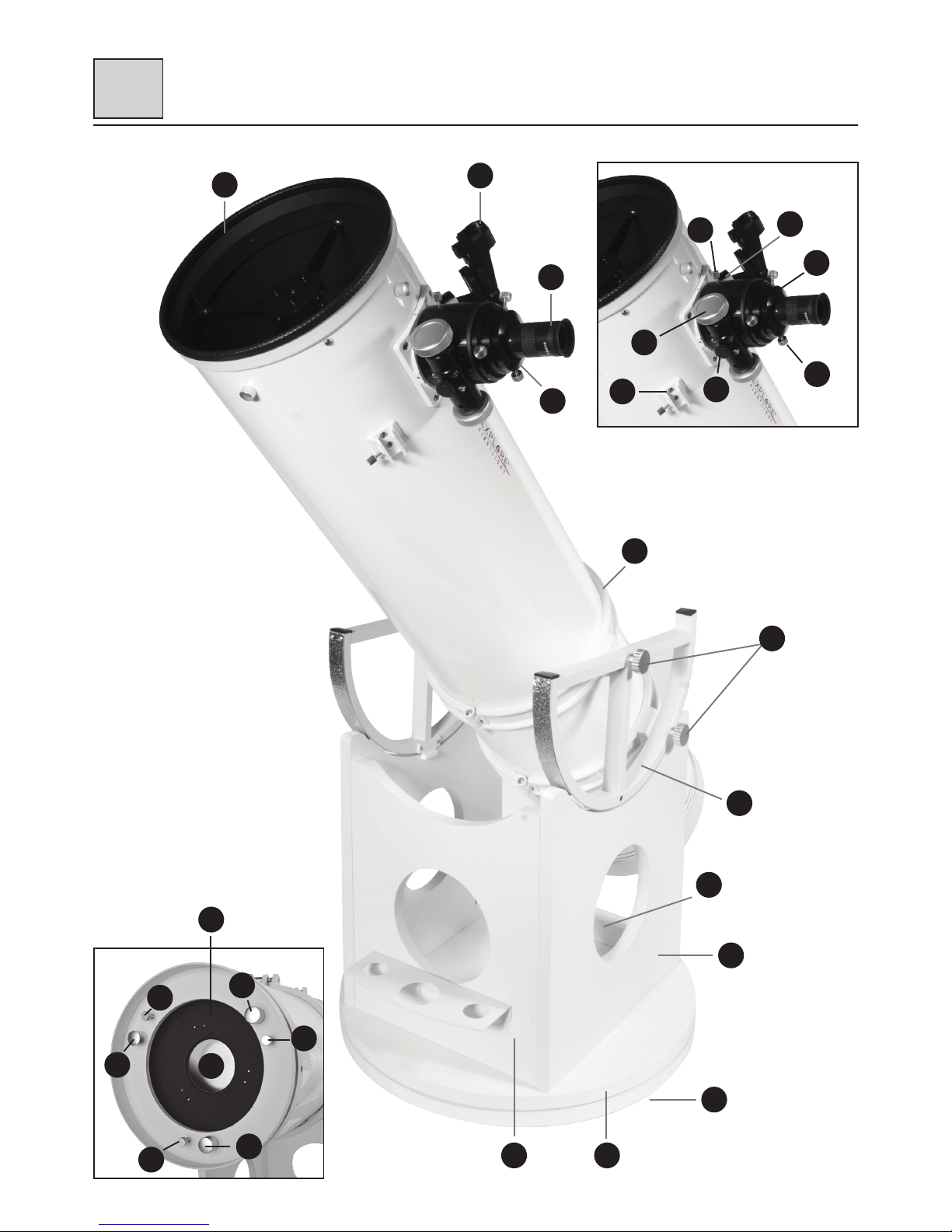
OTA (Optical Tube Assembly) (Fig. 2)
1. Eyepiece
2. Eyepiece holder
3. Aperture
4. Red dot viewfinder
5. OTA bracket (2x) with clamp screw
6. Fixing screws (4x)
7. Altitude wheels (2x) with lateral guids (7a)
Base (Fig. 2)
8. Base bridge
9. Base side parts (2x)
10. Base front part
11. Round base plate (2x)
12. Rubber feet (3x)
Eyepiece holder (Inset A)
13. Focusing drive
14. Friction screws (Focus lock and grinding pressure adjustment)
14a. Fixing screws
15. 1 ¼" and 2" eyepiece holder
16. Viewfinder mounting (2x)
17. Clamp screw
OTA's bottom side/mirror frame (Inset B)
18. Mirror backside
19. Mirror frame
20. Collimation screws (3x)
21. Counter screws (3x)
Parts Overview
II
Page 6
- 6 -
Setup
III
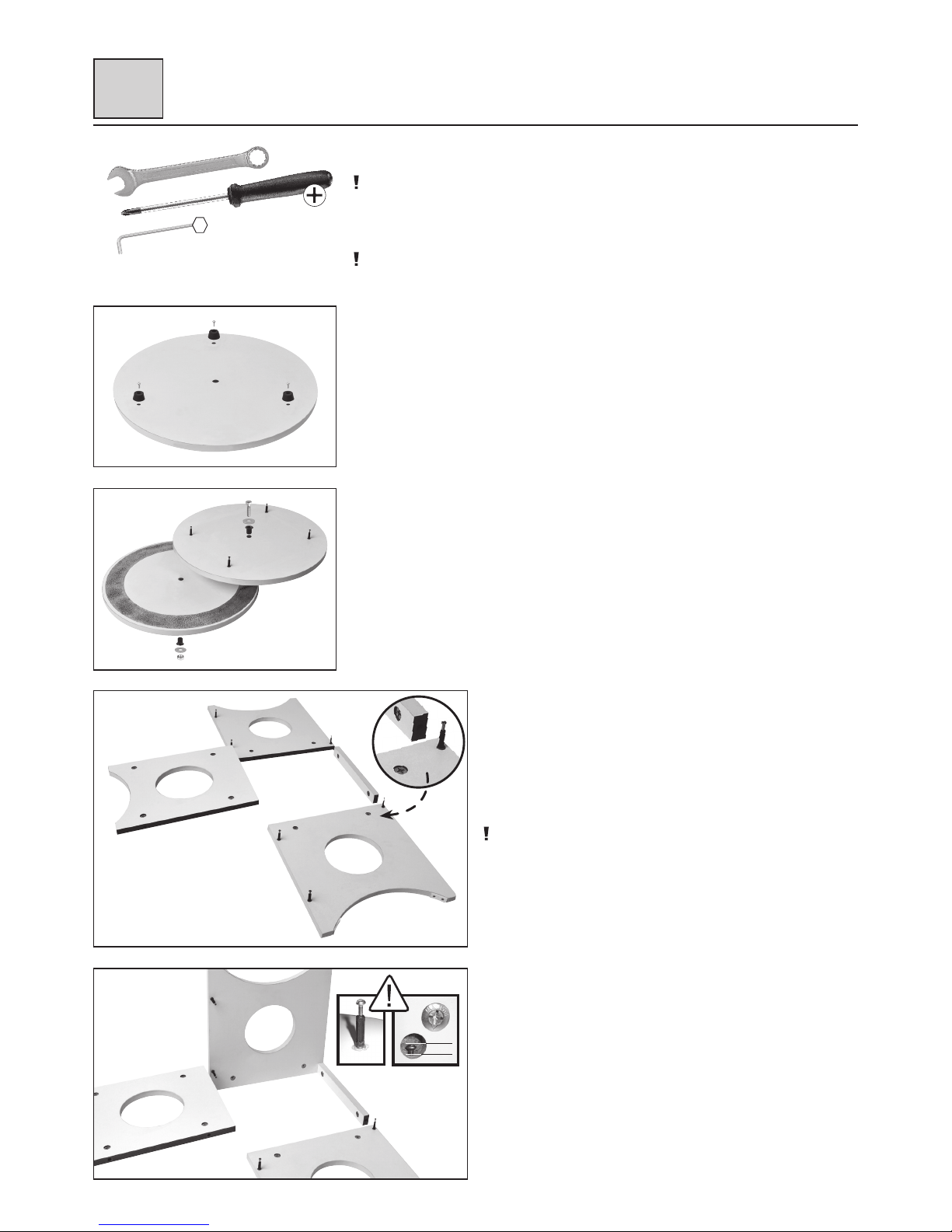
Assembling the Base
NOTE!
While assembling the base, you will need a Phillips screwdriver, a 2mm hex wrench and an
open-end wrench. We recommend assembling on a soft surface to avoid damaging the parts
of the base.
IMPORTANT!
Note that the studs are height-adjustable. It is therefore not necessary to screw in the studs
until they stop.
Important: Make sure that only approx. 4 mm of the stud heads are visible in the holes for the
quick fasteners. So the quick fastener and the stud head will interlock and all parts are firmly
connected. For that, install the studs accordingly in height (see Fig. A1).
STEP 1 (Fig. 3):
The base supports the optical tube assembly (OTA) and allows the OTA to be rotated 360°.
1. Put the first bottom plate (Fig. 1, A) on the floor and place the rubber feet (Fig. 1, S) over
the outer drill holes.
2. Screw each rubber foot down with a woodscrew (Fig. 1, N).
STEP 2 (Fig. 4):
1. Insert a plastic sleeve (Fig. 1, R) into the drill hole in the middle of both bottom plates
(Fig. 1, A + B).
2. Screw four threaded bolts (Fig. 1, L) into the outer drill holes of bottom plate on top.
3. Put both bottom plates on top of each other.
4. Bolt both bottom plates together with the fine-thread screw (Fig. 1, P) and the safety nut
(Fig. 1, O). Place one ring washer (Fig. 1, Q) on each side between the screw head or nut
and the plastic sleeve.
Fig. 3
Fig. 4
Tools Required
STEP 3 (Fig. 5):
1. Put all side parts (Fig. 1, C-F) on the floor.
2. Screw the threaded bolts (Fig. 1, L) into the small drill holes of both
side parts (Fig. 1, C + D).
3. Insert two quick fasteners (Fig. 1, M) into the large drill holes of
both side parts and the bridge (Fig. 1, E) and four quick fasteners
into the drill holes of the front part (Fig. 1, F).
NOTE!
Make sure that the opening at the bottom of the quick fasteners is
pointing to the drill hole on the edge. An arrow at the notch for the
Phillips head is showing the right direction.
STEP 4 (Fig. 6):
1. Set up the left side part (Fig. 1, C) and put the bridge (Fig. 1, E) with
its drill holes for the quick fasteners (Fig. 1, M) over the threaded
bolts (Fig. 1, L).
2. Tighten the quick fasteners with a Phillips screwdriver.
SW-17
PH-2 (6mm)
2 mm
Fig. 5
Fig. 6
max.
4 mm
Fig. A1
Page 7

- 7 -
STEP 5 (Fig. 7):
1. Set up the front part (Fig. 1, F) and put it with the drill holes of the
quick fasteners (Fig. 1, M) over the threaded bolts (Fig. 1, L) of the
left side part (Fig. 1, C).
2. Tighten the quick fasteners with a Phillips screwdriver.
STEP 6 (Fig. 8):
1. Set up the right side part (Fig. 1, D) and put it with the drill holes
of the qick fasteners (Fig. 1, M) over the remaining threaded bolts
(Fig. 1, L) of the bridge (Fig. 1, E) and the front part (Fig. 1, F).
2. Tighten the quick fasteners with a Phillips screwdriver.
3. Use two woodscrews (Fig. 1, N) to attach the accessory tray
(Fig. 1, G) to the front part.
STEP 7 (Fig. 9):
1. Put the complete base construction with the drill holes of the quick
fasteners at the bottom first (Fig. 1, M) over the threaded bolts
(Fig. 1, L) of the prepared bottom plate construction.
2. Tighten the quick fasteners (Fig. 1, M) with a Phillips screwdriver.
Setup
III
Fig. 7
Fig. 8
Fig. 9
max.
4 mm
Fig. A1
max.
4 mm
Fig. A1
Page 8
- 8 -
III
Attaching the OTA
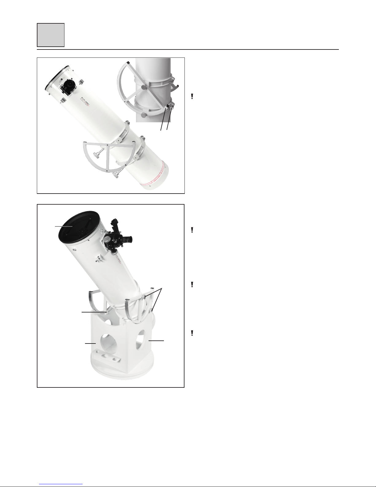
STEP 8 (Fig. 10):
1. Attach both altitude wheels (Fig. 1, H) with the fixing screws
(Fig. 1, T) to the right and left side of the OTA.
NOTE!
Make sure that the 'noses' on one side (Fig. 10, X) are pointing in
the direction of the clamp screws (Fig. 10, 5a) for the brackets and
that the lateral guides of the altitude wheels are pointing at one
another.
STEP 9 (Fig. 11):
1. Put the OTA with the attached altitude wheels into the half round
sections of the side parts (Fig. 11, 9).
NOTE!
Make sure that the aperture of the OTA (Fig. 11, 3) is pointing in the
direction of the front part (Fig. 11, 10) when attaching it.
2. Hold the OTA with one hand until it is balanced correctly. If
neccessary, move the OTA a little to another position within the
brackets (Fig. 11, 5) to establish a balance. Also when changing
the accessories a new balancing of the OTA is required.
NOTE!
Balancing is important because otherwise the tube could tip over at a
low imbalance and could be damaged.
3. Adjust the lateral guides (Fig. 11, 7a) of the altitude. Use a
suitable 2mm hex wrench. The side floating and the friction of the
altitude axis can be adjusted by evenly tigthening the four hex
screws (two per lateral guide).
NOTE!
Be careful not to over tighten the screws in order to avoid damage or
premature wear.
Fig. 10
X
5a
3
Fig. 11
Setup
5
9
10
7a
Page 9

- 9 -
Installing Accessories
IV
Inserting the Eyepiece (Fig. 12)
1. Insert the 1.25" eyepiece (Fig. 1, J) into the eyepiece holder (Fig. 12, 15).
2. Tighten the clamp screw (Fig. 12, 17) slightly.
3. Look through the eyepiece and turn the focusing wheel of the focusing drive (Fig. 12, 13)
right or left to focus the image.
4. When using a 2" eyepiece remove the 1.25" eyepiece adapter (Fig. 12, 15) from the holder
first.
5. Now insert the 2" eyepiece and fix it with the lock screw.
The eyepiece holder is equipped with a friction screw (Fig. 12, 14) on its bottom side and
with two fixing screws (Fig. 12, 14a) on its top side. Adjust the friction screw so that the
focusing drive can be moved sensitively. Additionally the focuser can be fixed with the fixing
screws to avoid unintentional adjustment.
NOTE!
Loosen the fixing screws on the focuser completely before you start focusing! Never tighten
the friction screw and fixing screws too firmly.
Attaching a Spacer Sleeve (Fig. 12a)
NOTE!
A spacer sleeve resolves focusing problems when the focusing point is not close to the
eyepiece extension. With a spacer sleeve it is, for example, possible to use the telescope for
photography or to use eyepieces with the telescope that offer an extreme focal position. It
is bridging the optical distance by its own length. When using a spacer sleeve, it is also no
longer necessary to turn out the eyepiece extension until it stops. It also increases mechanical
stability.
1. Unscrew the eyepiece holder (Fig. 12, 2a) and remove it from the eyepiece extension
(Fig. 12, 2).
2. Screw the spacer sleeve (Fig. 12, U) onto the eyepiece extension (Fig. 12, 2).
3. Screw the eyepiece holder (Fig. 12, 2a) onto the spacer sleeve (Fig. 12, U).
4. By screwing two or more optional spacer sleeves together, the optical distance can be
extended additionally.
Attaching the red dot viewfinder (Fig. 13)
Slide the red dot viewfinder holder into the track of the pre-installed holder base. Secure the
red dot viewfinder in place by tightening the screws on the side of the pre-installed bracket.
Attaching a 10:1 Micro Reduction Unit (optional) (Fig. 14)
A 10:1 micro reduction unit is available as an optional accessory and can be attached instead
of the normal reduction. It allows for normal focusing speed as well as for a focusing speed
that is reduced by ten times and therefore provides a very fine focusing. The optional 10:1
micro reduction unit is a special order from Germany, which means it can take several weeks
for delivery.
1. Loosen the hex screw at the bottom side of the right focusing wheel with a hex wrench.
2. Pull out the focusing wheel.
3. Insert the 10:1 micro reduction unit and tighten the hex screws of the drive shaft
(Fig. 14, X) and the hex screw of the housing (Fig. 14, Y) until sturdy.
Fig. 12
13
17
15
14a
14
Fig. 14
X
Y
Fig. 13
Fig. 12a
2a
2
U
Page 10

- 10 -
V
Using a Dobsonian Telescope
• Never lubricate the Teflon pads on the ground plate. Your Dobsonian has been designed
with some inherent friction. You want the telescope to move easily when you position it, but
you also want it to stay in the position you place it. Using any kind of oil, silicone spray, wax,
or grease will ruin the performance by causing the telescope to move too easily. Just keep
these bearing surfaces clean.
• The altitude bearing surfaces (Fig. 1, 7) of the telescope are lightly lubricated at the factory
for optimum performance. Over a period of time, these surfaces may become dry or dirty.
Simply clean off the bearing surfaces with a dry cloth or paper towel. Do not use solvents or
alcohol-based cleaning solutions as this may damage the bearings or the painted surfaces
of the telescope.
• You will notice that your telescope will move in altitude by raising and lowering the tube,
and in azimuth by rotating the base. As you observe objects in the night sky they will appear
to drift out of the field of view due to the Earth’s rotation. To keep an object centered in the
field of view, just lightly nudge the telescope in the proper direction. This may take a little
practice at first, but you’ll soon get the hang of it.
• Be sure the mount is placed on a relatively level surface to allow proper operation. Each of
the three feet should be in firm contact with the surface and not wobble. If you are in an
area with particularly rough or soft ground, it may be helpful to place the mount on a thick
piece of plywood.
• Part of the fun of using a Dobsonian type of telescope is the challenge of hunting for objects
in the night sky. Invest in some simple star charts and books that tell you how to locate
objects using a technique called “star hopping.” Once you begin learning the star patterns
and constellations, you’re well on your way to finding many amazing sights.
Calculating the Magnification
The magnification of a telescope is determined by two factors — the focal length of the
eyepiece and the focal length of the telescope.
To calculate the magnification of a given eyepiece use this formula:
Telescope focal length
Magnification = ----------------------------------
Eyepiece focal ength
For example, the included 25mm eyepiece will have a magnification of approximately 49x
when used with the 8” Dobsonian, which has a focal length of 1218mm.
1218 mm
Magnification = --------------- = 49x (approx. value)
25 mm
TIP: When beginning observations of an object, always start with your lowest power eyepiece.
Keep in mind that a bright, clearly resolved image will show far more detail than a poorly resolved
larger image.
Usage
Page 11

- 11 -
V
Align the Red Dot Viewfinder (Fig. 15)
Once the red dot viewfinder is mounted on the OTA, it is time to align it so that it and the
telescope will be centered on the same spot in the sky when it is time to use it.
Although the process can be tedious, it is important to follow through on all of the steps to
avoid later frustrations that can ruin an observing session.
We recommend doing that first alignment in the daytime using a land-based target.
Be careful to do this in an area where you will not accidentally point your telescope at or
near the Sun, (see Sun Warning in this Manual).
After you have set up your telescope and attached the red dot viewfinder, find an easy,
stationary target that is at least 200 meters away. We suggest using a streetlight or the top of
a telephone pole.
Insert the eyepiece into your telescope’s eyepiece holder and center the chosen target in the
telescope’s eyepiece. Look through the red dot viewfinder and loosen or tighten the adjusting
screws until the dot is precisely centered on the same target as the telescope.
Once night falls, center the Moon or a bright star in your finder scope then check the view in
your scope. Make small adjustments as needed.
Fig. 15
Usage
=
Page 12
- 12 -
V
Observation suggestions
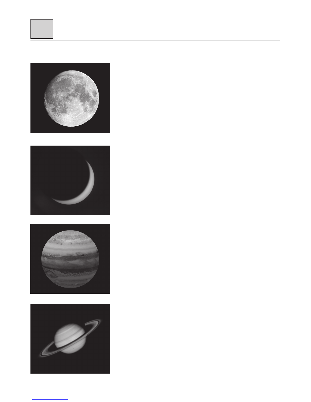
The Moon:
Diameter: 3,476 km
Distance: Approximately 384,401 km
The Moon is the Earth’s only natural satellite, and it is the second brightest object in
the sky (after the Sun). Although it is our closest neighbor, a lot of people have never
really taken a good long like at the Moon. With your telescope, you should be able
to see the intricacies of the lunar terrain — including lunar maria, which appear as
vast dark plains, craters and rilles. The best views will be found along the terminator,
which is the edge where the visible and cloaked portions of the Moon meet.
Planets
The planets are continuously changing their position in the sky, so it may help to
consult online resources to determine the correct place to look on any given night.
The following planets are especially suited for observations with a Dobsonian
telescope.
Venus
Venus is the third brightest object in the night sky, which makes it an ideal observing
target. The diameter of Venus is about 9/10th the diameter of the Earth. Viewing
Venus at different times in its orbit will reveal different phases (crescent, half and
full) much like the phases of our Moon. The planetary disc of Venus appears white
because the sunlight is reflected by a compact layer of clouds that covers all surface
details.
Mars
The diameter of Mars is about half that of the Earth's diameter. It will appear as a
red-orange disk, which may exhibit small white patches near the polar regions.
Observing Mars when it is closest to the Earth will show even more details, so it is a
good idea to consult online resources to determine when those dates might occur.
Jupiter
Jupiter is the biggest planet in our solar system and is the fourth brightest object in
the night sky. The equatorial diameter of this gas giant is 11 times bigger than that
of the Earth. Through the telescope, you should be able to see the cloud bands in
the atmosphere of Jupiter and the Great Red Spot. Even with low magnification, you
will be able to see the four Galilean moons — Io, Ganymede, Europa and Callisto —
as they march across the face of Jupiter. You might also be able to pick out some of
the many smaller moons of Jupiter.
Saturn
Saturn is a dynamic sight when viewed through a telescope. It will appear as a
round disc surround by its distinct ring structure. The rings of Saturn mainly consist
of billions of icy particles ranging from dust up to chunks that size of a house.
The Cassini division, which is a large gap in the rings, might be visible from your
telescope. You will also be able to see the largest of Saturn's moons — Titan — and
possibly others.
Deep sky objects
There are several types of deep sky objects that make excellent observing targets.
To locate specific targets it is important to have a star chart and be familiar with the
constellations. The following are types of deep sky objects that you can observe:
• Stars are giant objects that mainly consist of gas. They radiate energy and shine
because of nuclear fusion going on in their core. Due to the fact that star are
extremely far away, they appear as points of light both to the unaided eye and in
telescopes. However, with a telescope, you might be able to view separate members
of binary or multi-star systems.
Fig. 16: Craters of the moon are excellent targets to
observe even for beginners.
Fig. 17: Planet Venus in its thin crescent phase
Fig. 18: Jupiter's four largest moons can be observed in a
different position every night.
Fig. 19: Saturn is perhaps the most unforgettable sight to
see in a telescope.
Usage
Page 13

- 13 -
• Galaxies are gigantic accumulations of stars, nebulae and clusters that are held
together by gravity. Galaxies come in several shapes including spiral, elliptical,
barred and irregular. The closest spiral galaxy is the Andromeda Galaxy, and it is a
great observing target.
Andromeda Galaxy:
Right ascension: 00: 42.7 (hours: minutes)
Declination: +41: 16 (degrees: minutes)
Distance: Approximately 2.54 million light years
The Andromeda Galaxy is the closest major galaxy to our own Milky Way. Also
known as Messier 31, this famous spiral galaxy is part of the Local Group of galaxies.
Although it is technically bright enough to see with the unaided eye under a very
dark sky, your telescope may show its bright center, hints of its spiral structure and
its much smaller companion galaxies known as M32 and M110.
• An open cluster is a group of young stars that were born in a single diffuse nebula
not too long ago (on an astronomical time scale…). One of the most popular open
star clusters for observers is the Pleiades:
Pleiades Star Cluster:
Right ascension: 03: 47.0 (hours: minutes)
Declination: +24: 07 (degrees: minutes)
Distance: Approximately 444 light years
The Pleiades Star Cluster is a group of brilliant blue stars located in the Taurus
Constellation. Also known as Messier 45 or “Seven Sisters”, this open star cluster
consists of more than 1,000 confirmed stars, although an average of only six are
visible to the unaided eye. With your telescope, you can quickly reveal some of the
more elusive members of this legendary and beautiful cluster.
• Nebulae are giant interstellar clouds of gas and dust. Within those clouds new stars
are born. The premier nebula on the northern hemisphere is the Great Orion Nebula:
Orion Nebula:
Right ascension: 05: 35.4 (hours: minutes)
Declination: -05: 27 (degrees: minutes)
Distance: Approximately 1,344 light years
The Orion Nebula is a vast star-forming region located in the “sword” branching off
of the famous Orion’s Belt. Also known as Messier 42, this diffuse nebula is bright
enough to see with the unaided eye — although it will only appear as a slightly
foggy star. However, with your telescope, you can see many of the beautiful details,
such as the billowing clouds of gas and dust where new stars are being born.
When you become an advanced observer you can look for other types of objects
such as asteroids, planetary nebula and globular clusters. And if you’re lucky, every
so often a bright comet appears in the sky, presenting an unforgettable sight. The
more you learn about objects in the sky, the more you will learn to appreciate the
sights you see in your telescope. Start a notebook and write down the observations
you make each night. Note the time and the date. One of the best methods to record
your telescopic views is astronomical sketching. It improves your ability to see fine
detail and subtle variations in brightness.
Many astronomical magazines and online forms give the opportunity to get in
contact with other amateur astronomers. Online resources like www.cloudynights.
com or www.stargazerslounge.com help to build up knowledge and get to know
other aspects of the hobby. The more you know about it, the more fun this hobby
will be!
V
Fig. 20: M31, the Andromeda Galaxy, is one of the easiest
galaxies to locate and observe during the fall and winter
evenings.
Fig. 21: The Pleiades Star Cluster is probably the
most striking star cluster to observe in the Northern
Hemisphere.
Usage
Page 14

- 14 -
V
Useful Tips
Because of the Earth's rotation all objects in a telescope's eyepiece will seem to drift across the
field of view. To compensate for this movement you have to move the telescope smoothly
and slowly. The higher the magnification the more accurate this tracking movement has to
be. Another solution is to place the object on the eastern rim of the field of view and let it drift
across the field, then reposition it on the eastern rim again. NOTE: This method only works
with good eyepieces that are delivering a sharp image up to the edge of the field.
Vibrations: Avoid touching the eyepiece during observations because even the slightest
movement in your hand can cause unsteady views.
Dark adaption: Give your eyes some time to adapt to the darkness. This takes about 20-30
minutes after an exposure to a bright light – even if it is a short exposure. Use a dim light with
a red filter to read star charts or draw objects.
Planets and other objects that are close to the horizon are severely influenced by air turbulence
and absorbance. It is much better to time your observations in a way that those objects are
close to the meridian, so that they are at their highest position possible. If the image is dim
or moving fast, use a smaller magnification. Using too much magnification is a mistake that is
made very often by beginners.
Warm clothing: Even in the summer the nights may get very cold during clear nights,
especially on the mountains. Always remember to bring warm clothing like thick jackets,
beanies, gloves, winter shoes and thick socks – even if your were sweating during the day. It
is hard to enjoy even the best night when you are freezing!
Explore your observing site during the day: The ideal site should be far away from
frequently used streets and other light sources that would prevent your eyes to become dark
adapted. Keep in mind that it is likely to get foggy in the vicinity of open water, such as river
valleys or lakes. The ground should be solid and relatively flat. You can observe in the city, but
try to get to a place some distance away, where you can see the Milky Way if possible.
Usage
Page 15

- 15 -
Maintenance and Cleaning
VI
Proper Care
Your telescope is a precision optical device and keeping the optics free of dust and dirt is
crucial for optimal performance. However, the use of improper cleaning techniques, tools
and/or solutions can cause irreparable damage to your telescope.
In terms of solutions, use distilled water and/or an optical glass cleaner that can be found at
most camera stores.
Only use pure cotton swabs/balls or white, unscented, lotion-free tissues for wiping down
optics after you have removed as many particles as possible with forced air or a photographicgrade camel hair brush. DO NOT use optical lens cleaning tissues as many contain fiberglass
particles that can be abrasive.
Collimation
All telescopes are collimated precisely at the factory before shipment. However, a telescope
that was disassembled has to be freshly collimated after reassembly. Collimating a telescope
is a straightforward procedure that is not very difficult. The collimation procedure is slightly
different from that of other Newtonian reflecting telescopes, because of the "fast" f/5 to f/6
focal ratio of the primary mirror. In typical Newtonian reflectors with more conventional focal
ratios (i.e. longer focal ratios), when the observer looks down the focuser tube (without an
eyepiece in the focuser), the images of the diagonal mirror, primary mirror, focuser tube and
the observer's eye appear centered relative to each other.
However, with the short focal ratio primary mirror of this Dobsonian telescope, correct
collimation requires that the diagonal mirror be offset in 2 directions: (1) away from the
focuser and (2) towards the primary mirror, in equal amounts. This offset is approximately
1/8" in each direction. Note that these offsets have been performed at the factory prior to
shipment of your telescope. It is only necessary for you to confirm that the telescope has not
been badly jarred out of collimation, and to perform the final fine-tuning of Step 4, below. To
check and, if necessary, set the optical collimation, follow these steps:
1. Observe through the focuser and orient your body so that the telescope's primary mirror
is to your right, and the open end of the telescope tube is to your left. The diagonal mirror
will appear centered and round as shown (Fig. 24). If the diagonal appears off center, then
adjust the 3 collimation screws on the diagonal mirror housing.
2. If the reflection of the primary mirror (Fig. 24) is not centered on the surface of the diagonal
mirror, adjust the 3 collimation adjustment screws on the diagonal mirror housing to center
the reflection. As described above, the 3 collimation screws (Fig. 22, 2) on the diagonal
mirror housing are used for two different adjustments during the collimation procedure.
Fig. 21: Newtonian reflecting telescope. Spider vanes (1); secondary mirror (2); parabolic primary mirror (3); primary mirror adjustment screws (4); focuser drawtube (5); focused image (6).
Page 16

- 16 -
VI
NOTE!
Do not force the 3 screws (Fig. 22, 2) past their normal travel.
Do not rotate the collimation screws more than two full turns in a counterclockwise direction
(i.e. not more than two full turns in their "loosening" direction), or else the diagonal mirror
may become loosened from its support. NOTE: The diagonal mirror collimation adjustments
are very sensitive. In general, turning a collimation screw a half turn will have a dramatic effect
on collimation.
3. If the reflection of the diagonal mirror is not centered within the reflection of the primary
mirror, adjust the 3 collimation adjustment screws located on the rear of the primary mirror
cell.
NOTE!
The primary mirror housing (Fig. 23) is equipped with 6 screws. The 3 large knurled screws
are collimation screws (Fig. 23, 21) and the 3 smaller knurled screws are lock screws
(Fig. 23, 20). These lock screws must be loosened before the collimation screws can be
turned. Proceed by "trial and error" until you develop a feel for which collimation screw to
turn in order to change the image in any given way.
4. Perform an actual star test to confirm the accuracy of steps 1 through 3. Using the 25mm
eyepiece, point the telescope at a moderately bright (second or third magnitude) star, and
center the image in the main telescope's field of view.
5. Bring the star's image slowly in and out of focus until you see several disks surrounding
the star's center. If steps 1 through 3 were done correctly, you will see concentric (centered
with respect to each other) circles (Fig. 25, 1). An improperly collimated instrument will
reveal oblong or elongated circles (Fig. 25, 2). Adjust the 3 collimating screws on the
primary mirror housing until the circles are concentric on either side of the focus.
In summary, the adjustment screws on the diagonal mirror housing change the tilt of the
secondary mirror so that it is correctly centered in the focuser drawtube, and so that the
primary mirror appears centered when looking into the focuser. The 3 collimating knobs on
the primary mirror change the tilt of the primary mirror so that it reflects the light directly up
the center of the drawtube.
20
21
20
21
21
20
Fig. 23: Underside of rear mirror tube (primary mirror
housing). Collimation screws (20); Lock screws (21).
Fig. 22: Secondary Mirror Assembly (front and side view).
Spider vanes (1); tilt screws (2); secondary mirror holder (3).
Fig. 24: View you see while collimating the telescope
(without eyepiece inserted). Focuser drawtube (1);
diagonal mirror (2); reflection of primary mirror (3);
reflection of secondary mirror (darkened due to back
lighting) (4); primary mirror holder (5); reflection of
observer's eye (6)
Fig. 25: Correct (1) and incorrect (2) collimation as viewed
during a star test.
Maintenance and Cleaning
Page 17

- 17 -
Optional Accessories
VII
Technical Data
FirstLight 8” Dobsonian
Primary mirror diameter: 203mm (8”)
Secondary mirror obstruction: 24%
Focal length: 1218mm
Focal ratio: f/6
Theoretical resolving power: 0.74 arc seconds
Limiting magnitudes: 13.5 mag
Focuser: 2.5” Hex focuser with 2” and 1.25” adapter
Included eyepiece: SuperPlossl 25mm
Weight (OTA): 25lbs / 11kg
Weight (Base): 21lbs / 9.5kg
Total weight: 46lbs / 21kg
FirstLight 10”Dobsonian
Primary mirror diameter: 254mm (10”)
Secondary mirror obstruction: 24%
Focal length: 1270mm
Focal ratio: f/5
Theoretical resolving power: 0.59 arc seconds
Limiting magnitudes: 14 mag
Focuser: 2.5” Hex focuser with 2” and 1.25” adapter
Included eyepiece: SuperPlossl 25mm
Weight (OTA): 36lbs / 16.3kg
Weight (Base): 25lbs / 11.3kg
Total weight: 61 lbs/ 27.6kg
VI
BRESSER Messier
10:1 Micro reduction unit
with HEXAFOC focuser
Item No. 0625720
EXPLORE SCIENTIFIC
8x50 Illuminated Finder Scope
Item No. VFEI0850-01
EXPLORE SCIENTIFIC
8x50 non-illuminated finder scope
Item No. VFO8505
EXPLORE SCIENTIFIC
8x50 illuminated polar
right angle finder scope
Item No. VFEI0850-RA
Product Information
Page 18

- 18 -
Disposal Information
VIII
Dispose of the packaging materials properly, according to their type (paper, cardboard, etc.). Recycle when
possible. Contact your local waste disposal service or environmental authority for information on the proper
disposal.
Please take the current legal regulations into account when disposing of your device. You can get more information
on the proper disposal from your local waste disposal service or environmental authority.
Page 19

- 19 -
Page 20

© 2018 Explore Scientific, LLC.
1010 S.48th Street, Springdale, AR 72762
explorescientificusa.com | exploreone.com | 866.252.3811
All rights reserved. Made in China.
Rev. 02/19/2018
 Loading...