

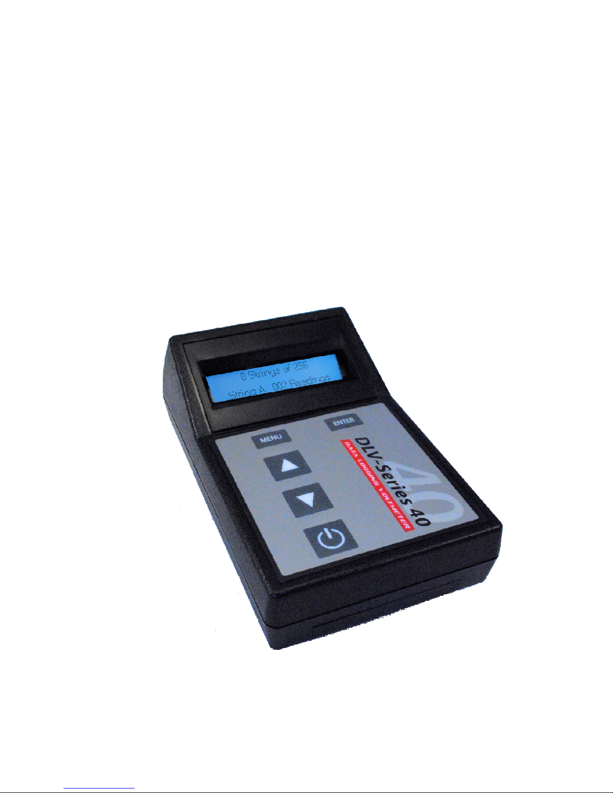
Operator’s Manual:
40 Data logging Voltmeter
DLV
Rev: 02
Date: 5/28/2012
DLV40 Firmware: Rev 000.008 and above
Winmeter 5.0 Software: Rev 1.0.0 and above

Table of Contents:
1.0
2.0
3.0
4.0
Overview
User Interface
1.1
1.1.1
1.1.2
Graphical Back lit LCD Display (128x32)
Membrane Keypad
Menu System
2.1
2.2
2.3
2.4
Main Menu
Discharge Sub-Menu
“20 x 48” Sub-Menu
“8 x 256” Sub-Menu
Power Saving Features
3.2
3.2
3.3 Checking battery Voltage
Taking a Measurement (ALL Modes)
Auto-Off
Low Battery Indication
5.0
4.1
4.2
4.3
Over Voltage Indication (ALL Modes)
Recording Over a Previous Measurement (ALL Modes)
Deleting a Previous Measurement (ALL Modes)
Discharge Test Procedure
5.1
5.2
5.3
5.4
5.5
5.6
Step1: Select DLV40 “Discharge Test” Mode & Clear Existing Test Data
5.1.1
5.1.2
Step 2: Measure String Float Cell Voltages
Step 3: Starting the Discharge Test Timer & Taking Discharge Readings
Step 4: Upload Discharge Test Data to Winmeter 5.0
Step 5: Generate Cell Discharge Report(s)
Step 6: Save Cell Discharge Report(s)
Option 1: Using Winmeter 5.0 Software
Option 2: Manually

6.0 Float Test Procedure (“8x256” and “20x48” Modes)
7.0
6.1
6.2
6.3
6.4
6.5
6.6
Step1: Select DLV40 “8x256” /“20x48” Mode & Clear Old String Data
6.1.1
6.1.1
Option 1: Using Winmeter 5.0 Software
Option 2: Manually
Step 2: Measure String Float Cell Voltages
Step 3: Upload “8x256/20x48” Test Data to Winmeter 5.0
Step 4: Select Float String to Save
Step 5: Generate Cell Float Report(s)
6.5.1
6.5.2
6.5.3
Add/Edit Report Information and Parameters
View/Print Report(s)
6.5.2.1
6.5.2.2
6.5.2.3
Graphs
Tabular Report
Saving Report to PDF or Excel Format
Export Data to Excel (Optional)
Step 6: Save Cell Test Report(s)
Connecting the DLV40 to PC/Winmeter 5.0
Upgrading DLV40 Firmware
8.0
For the most accurate results, please read and follow these instructions carefully.

1.0 Overview
All
DLV40 modes operate
independent
ly
. Erasing the memory in one mode does
NOT
affect readings in the remaining (2) modes
.
The DLV40 data logging voltmeters have been designed specifically for the battery test industry. The
DLV40 is designed to measure and automatically record DC cell voltages between 0.1 VDC and 19.999
VDC (inclusive). It has a built in real time clock and calendar which allows for date and time stamping of
readings. The stored readings can then be transferred to a PC via a standard USB connection and the
companion Winmeter 5.0 Battery Analysis Software.
The DLV40 is capable of operating in (3) distinct measuring modes:
(i) “8 by 256” Mode: The DLV40 can measure and store up to 2048 readings of cell voltage.
These readings are stored in 8 separate data strings of 256 readings, denoted A through H.
The date and time of the last reading in each string is also recorded.
(ii) “20 by 48” Mode: The DLV40 can measure and store up to 960 readings of cell voltage.
These readings are stored in 20 separate data strings of 48 readings, denoted A through T.
The date and time of the last reading in each string is also recorded.
(iii) “Discharge Test” Mode: The DLV40 can measure and store up to 2048 readings of cell
voltage. These readings are stored in 8 separate data strings of 256 readings, denoted A
through H.
Readings in String A are reserved for the initial (float) voltage of the cell and are NOT time
stamped.
Readings in Strings “B” through “H” are reserved for cell voltages during the discharge (or
charge) test with each reading being time stamped to the nearest second from the start of
the discharge test. The date and time of the last reading is also recorded.
All stored readings can be downloaded via Winmeter 5.0 software to generate detailed test reports
including statistical and graphical analysis and then stored into a custom database. This software
communicates with the DLV40 via USB and allows the User to set the time/date, change modes, delete
data string(s) and upgrade the DLV40 firmware via PC interface.

1.1 User Interface
selection.
B:001
000.0
into the test).
“Discharge Test”
Mode
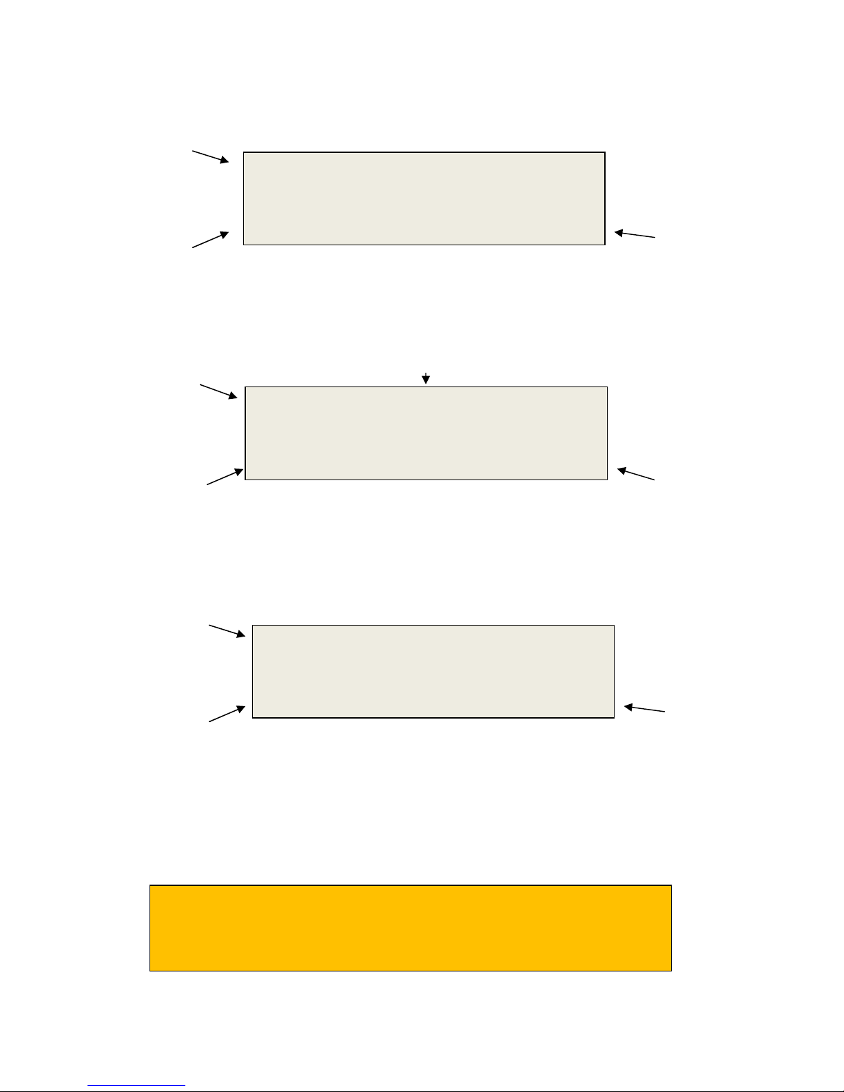
1.1.1 Graphical Back lit LCD Display (128x32)
Current measurement
mode.
Selected String (“B”) and
the next reading in the
selected string (“001”).
(Float readings have been
taken but no discharge
readings have been
taken).
1.1.2 Membrane Keypad
MENU
From measurement mode:
Push once to enter the
sub-menu.
Push twice to enter Main
menu.
Dischg
Discharge Time
(Currently 3 seconds
0:00:03
+0.000
Sum of cell voltages
for the selected
string.
Shows 000.0 as no
discharge readings
have been taken.
ENTER
Push to accept the current
UP & DOWN
Main or sub menu mode:
Push to change the current
selection.
Measurement mode: Push
to change selected
readings.
ON/OFF:
“Short” push to turn ON
“Long” push to turn OFF
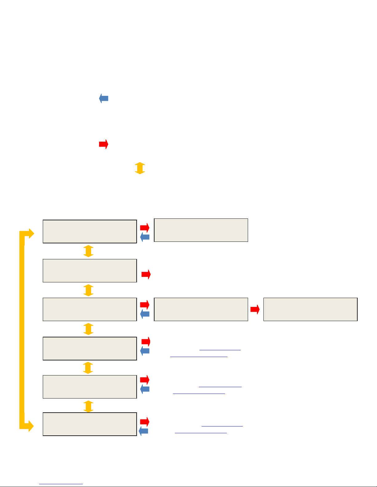
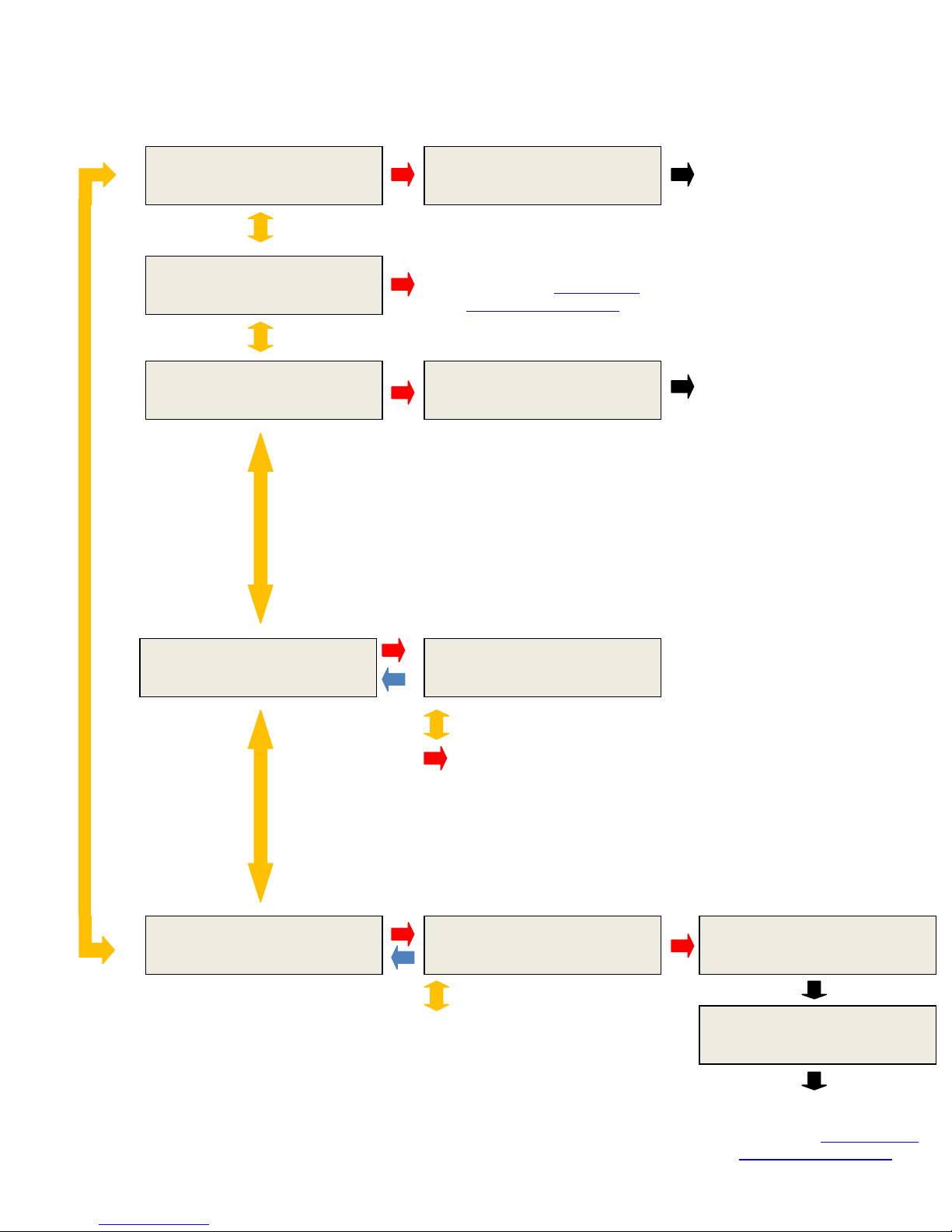
2.0 Menu System
DLV40 Rev: 000.005
The DLV40 uses a simple two tier menu system. The “Main Menu” and (3) sub-menus, one for each
measurement mode (“8 by 256”, “20 by 48” and “Discharge Test”).
2.1 Main Menu
“MENU” Button:
When the DLV40 is in one of the measurement modes, push the MENU button once to enter the
appropriate sub-menu, push the MENU button a second time to enter the Main Menu.
When the DLV40 is in the Main Menu, push once to cancel the current selection.
“ENTER” Button:
Push the ENTER button to accept the current selection.
“UP” and “DOWN” Buttons:
In Main or sub-menu modes push to change the current selection.
In any of the (3) measurement modes push once to increment/decrement the cell pointer, push and
hold to scroll through the readings.
*** Main Menu***
About DLV40
*** Main Menu***
Date & Time?
*** Main Menu***
Delete ALL Data
*** Main Menu***
MODE : DISCHARGE
*** Main Menu***
MODE : 20 by 48
*** Main Menu***
MODE : 8 by 256
09-15-11 14:30:21
Battery 95% Cal: 06-15-11
Displays Date & Time
(Date/Time is set via USB
connection
with Winmeter 5.0)
*** Main Menu***
Delete ALL Data?
Discharge Test Mode
(Please refer to Section 5.0 for the
Discharge Test Procedure )
20 by 48 Mode
(Please refer to Section 6.0 for the
Float Test Procedure(s) )
8 by 256 Mode
(Please refer to Section 6.0 for the
Float Test Procedure(s) )
*** Main Menu***
Delete Data 05%
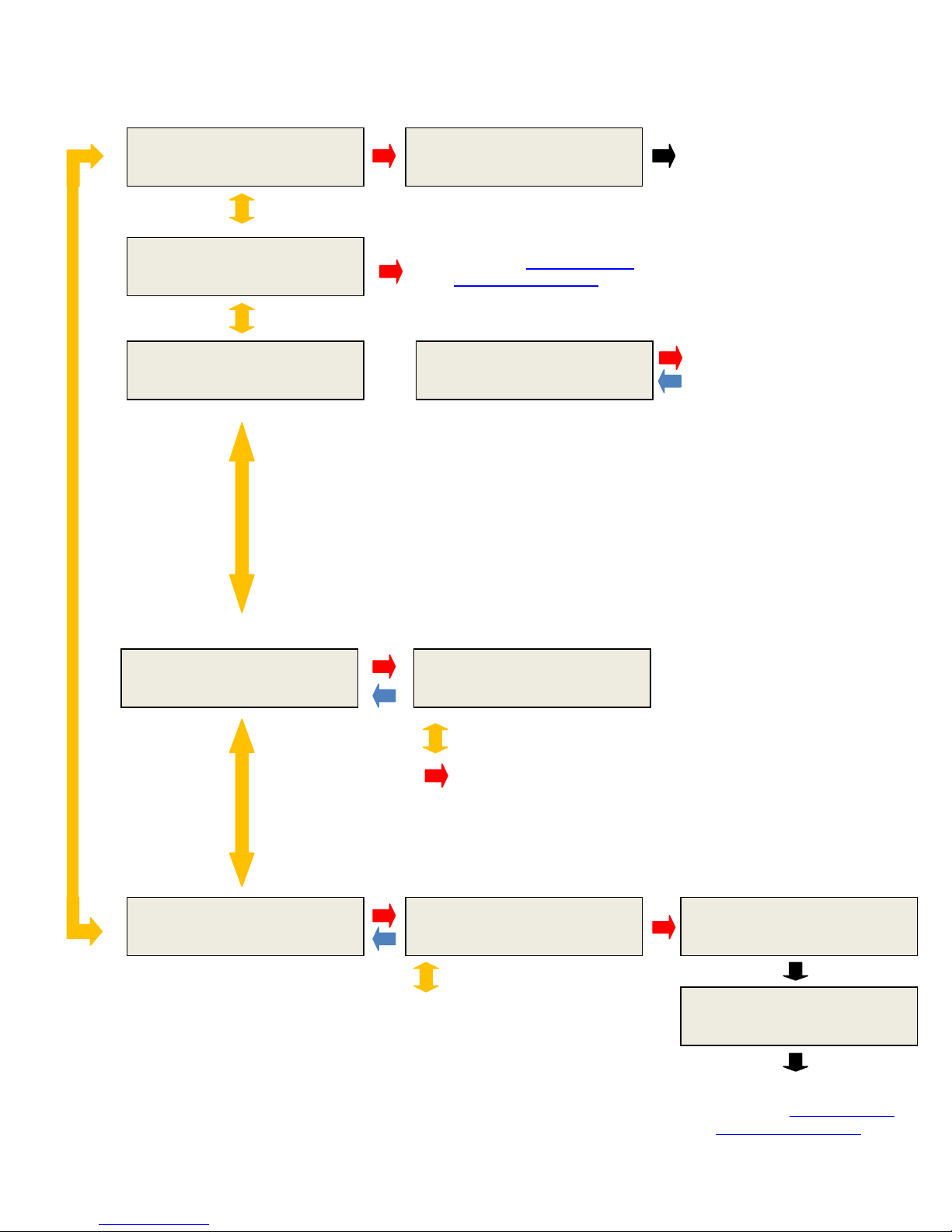
2.2 “Discharge” Sub-Menu
Discharge Test Procedure
)
OR
UP/DOWN
Discharge Test Mode
UP/DOWN
*** Discharge Menu***
Delete B:003?
*** Discharge Menu***
Exit?
*** Discharge Menu***
Start DC Test?
*** Discharge Menu***
Change String?
*** Discharge Menu***
Print String?
*** Discharge Menu***
Reading Deleted
Discharge Test Mode
(Please refer to Section 5.0 for the
Discharge Test Procedure )
*** Discharge Menu***
Delete DC Test?
Discharge Test
String A 024 Readings
to change strings
ENTER to select and return to
*** Discharge Menu***
Print VDC String B?
to change strings
Discharge Test Mode
(Please refer to section X.X for
more information)
Start/Delete Discharge Test
lease refer to section X.X (Start)
P
and section X.X (Delete) more
information.
*** Discharge Menu***
Printing Data…
*** Discharge Menu***
Printing Complete
Discharge Test Mode
(Please refer to Section 5.0 for the
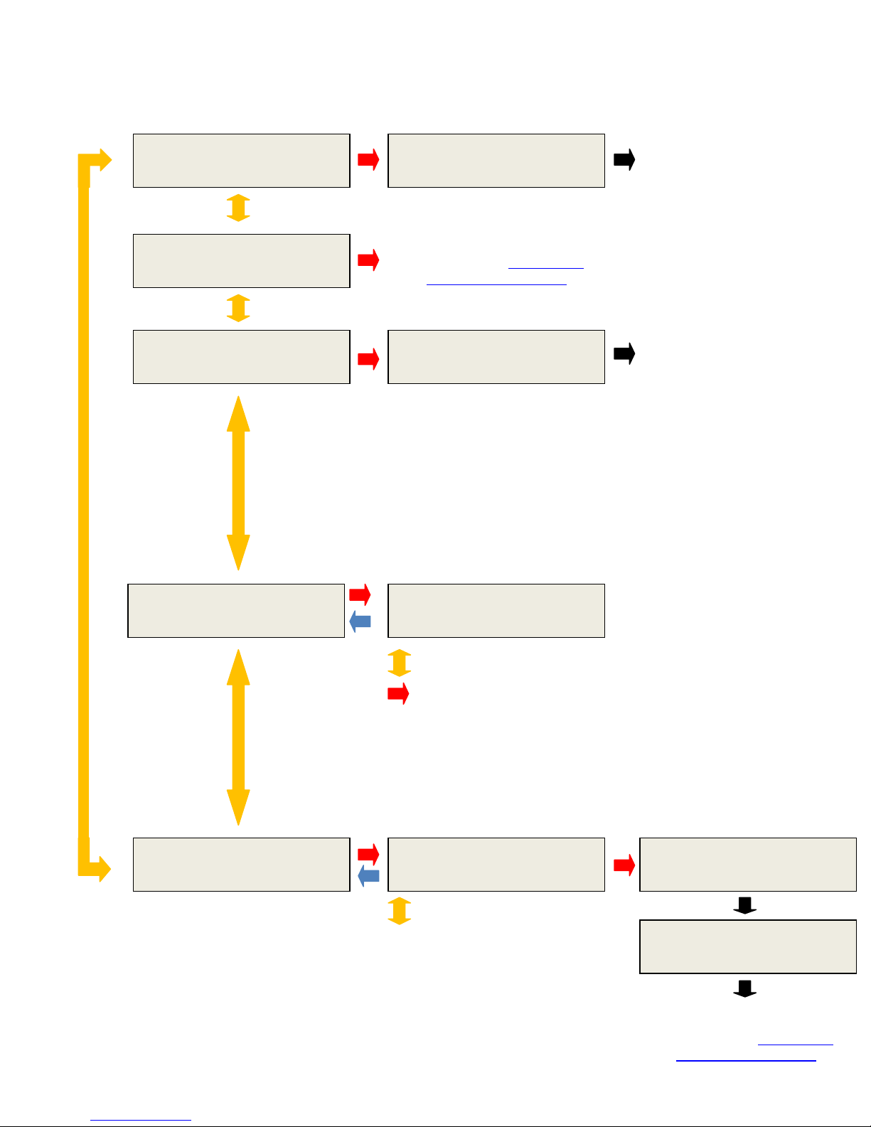
2.3 “20 by 48” Sub Menu
UP/DOWN
Discharge Test Mode
UP/DOWN
*** 20 x 48 Menu ***
Delete J:025?
*** 20 x 48 Menu***
Exit?
*** 20 x 48 Menu***
Delete String J?
*** 20 x 48 Menu***
Change String?
*** 20 x 48 Menu***
Print String?
*** 20 x 48 Menu***
Reading Deleted
20 x 48 Test Mode
(Please refer to Section 6.0 for
the Float Test Procedure(s) )
*** 20 x 48 Menu***
Deleting String J…
*** 20 x 48 Menu***
String J 024 Readings
to change strings
ENTER to select and return to
*** 20 x 48 Menu***
Print VDC String J?
to change strings
20 x 48 Test Mode
(Please refer to section X.X for
more information)
20 x 48 Test Mode
(Please refer to section X.X for
more information)
*** 20 x 48 Menu***
Printing Data…
*** 20 x 48 Menu***
Printing Complete
20 x 48 Test Mode
(Please refer to Section 6.0 for
the Float Test Procedure(s) )
2.4 “8 by 256” Sub Menu
UP/DOWN
Discharge Test Mode
UP/DOWN
*** 8 x 256 Menu ***
Delete A:025?
*** 8 x 256 Menu***
Exit?
*** 8 x 256 Menu***
Delete String A?
*** 8 x 256 Menu***
Change String?
*** 8 x 256 Menu***
Print String?
*** 8 x 256 Menu***
Reading Deleted
8 x 256 Test Mode
(Please refer to Section 6.0 for
the Float Test Procedure(s) )
*** 8 x 256 Menu***
Deleting String A…
*** 8 x 256 Menu***
String B 024 Readings
to change strings
ENTER to select and return to
*** 8 x 256 Menu***
Print VDC String B?
to change strings
8 x 256 Test Mode
(Please refer to section X.X for
more information)
8 x 256 Test Mode
(Please refer to section X.X for
more information)
*** 8 x 256 Menu***
Printing Data…
*** 8 x 256 Menu***
Printing Complete
8 x 256 Test Mode
(Please refer to Section 6.0 to for
the Float Test Procedure(s) )
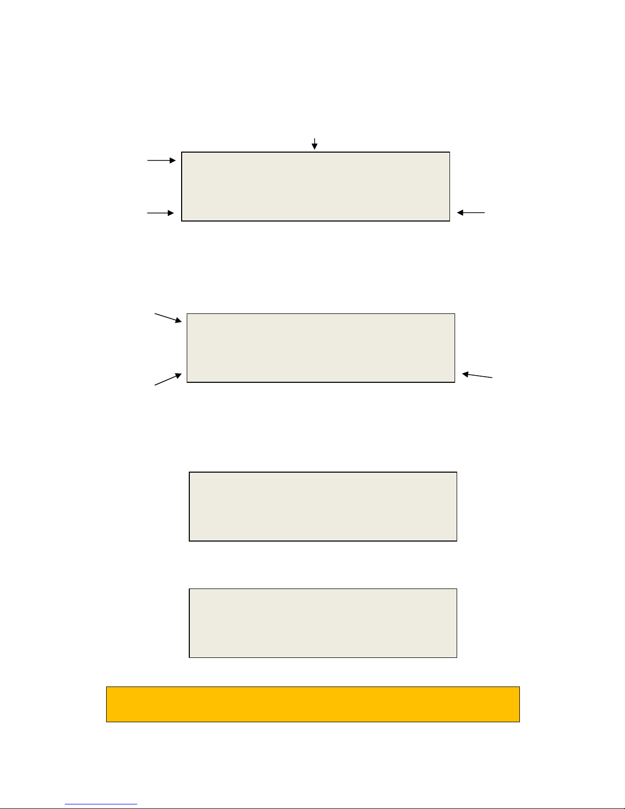
3.0 Taking a Cell Voltage Measurement (ALL Modes)
B:001
000.0
When turned
ON
, the DLV40 will automatically resume in the previous mode and “point” to the next
“20x48” or “8X256” Mode
B:001
000.0
“Discharge Test”
Mode
The DLV
40 USB cable
MUST
be
DISCONNECTED
whenever measuring voltages
!
The DLV40 is designed to measure absolute DC cell voltages between 0.1 VDC and 19.999 VDC.
Attempts to measure higher DC voltages will result in an “OVERVOLTAGE!!!” warning.
Cell voltage measurements are taken in a similar fashion to a traditional voltmeter.
(i) Turn the DLV40 ON.
(ii) Select the required measurement mode (“20x48”, “8x256” or “Discharge”).
reading location.
(Please refer to section X.X for Mode selection for more information)
(iii) Select required string.
For “20x48” or “8x256” mode:
- If old data is present, delete string(s) data as required.
For “Discharge Test” mode:
If an old Discharge Test data is present, delete the existing Discharge Test data.
Current measurement
mode.
Selected String (“B”) and
the next reading in the
selected string (“001”).
(No readings have been
taken).
Current measurement
mode.
Selected String (“B”) and
the next reading in the
selected string (“001”).
(Float readings have been
taken but no discharge
readings have been
taken).
8x256
+0.000
Dischg 0:00:03
+0.000
Sum of cell voltages
for the selected string
(shows 000.0 as no
discharge readings
have been taken).
Discharge Time
(Currently 3 seconds
Sum of cell voltages
for the selected string
(shows 000.0 as no
discharge readings
have been taken).
(iv) Connect the voltage probes to the cell terminals.
B:001
000.0
“20x48” or “8X256” Mode
B:001
000.0
“Discharge Test”
Mode
B:
002
002.3
reading has been taken
.
“20x48” or “8X256” Mode
B:
002
002.3
removed from cell
.
taken
).
stored)
.
The DLV40 automatically detects that it is connected to a cell and begins taking
measurements. When the readings are stable (within +/- 0.005 VDC) the DLV40
automatically beeps, the backlight flashes and the reading is held on the display.
Current measurement
mode.
Selected String (“B”) and
the next reading in the
selected string (“001”).
(No readings have been
taken).
Current measurement
mode.
Selected String (“B”) and
the next reading in the
selected string (“001”).
(Float readings have been
taken but no discharge
readings have been
(v) Remove the voltage probes from the cell terminals.
The reading is held on the display until the probes are removed. After approximately (1)
second the DLV40 stores the reading, adds the reading to the sum of string cell voltages and
increments to the next reading.
Current measurement
mode.
Selected String (“B”) and
the next reading in the
selected string (“002”).
((1) reading has been
stored).
Current measurement
mode.
Selected String (“B”) and
the next reading in the
selected string (“002”).
((1) reading has been
8x256 HLD
+2.345
Dischg HLD
+2.345
8x256
+0.000
Dischg 0:00:09
+0.000
“Discharge Test” Mode
Readings “held” on
display until probes are
Sum of cell voltages
for the selected
string.
(Shows 000.0 until
probes removed).
Readings “held” on
display until probes are
Sum of cell voltages
for the selected
string.
(Shows 000.0 until
probes removed).
Sum of cell voltages for
the selected string.
(Shows 002.3 as (1)
Discharge Time
(Now 9 seconds into
Sum of cell voltages for
the selected string.
(Shows 002.3 as (1)
reading has been
(vi) Repeat steps (iv) and (v) until all cell voltages in the string have been measured.
In
“Discharge Test”
mode:
- The string capacity of the discharge strings (B through H) is limited to the number of
readings in float string (String A).
- Once the last discharge reading is taken, (strings B through H), the DLV40 will automatically
increment to the next string.
- The user then must wait for the required test interval before taking the next set of discharge
cell voltage readings. The required test interval is typically ~Discharge test length divided by
(7)
For “20x48” or “8x256” modes, please refer to
Section 6.0 to for the Float Test Procedure(s).
For “Discharge Test” mode, please refer to
Section 5.0 to for the Discharge Test Procedure.
3.1 Over Voltage Indication (ALL Modes)
The DLV40 provides both an audio and visual indication if the probes are connected to an
excessive input voltage (Vin < -19.999 VDC or Vin > +19.999 VDC)
The unit will beep continuously and display:
This warning is removed as soon as the probes are disconnected from the high voltage source.
OVER VOLTAGE!!!
3.2 Recording Over a Previous Measurement (ALL Modes)
B:
003
046.6
B:
020
046.6
been stored
).
readings stored in location
been stored
).
B:003
046.6
been stored
).
In
“Discharge Test”
mode:
To record over a previous measurement:
Current measurement
mode.
Selected String (“B”) and
the next reading in the
selected string (“002”).
((1) reading has been
Current measurement
mode is replaced with
“MEM” to signify
reading is from memory
(B:003).
Selected String (“B”) and
the current reading in the
selected location (“003”).
Current measurement
mode.
Selected String (“B”) and
the next reading in the
selected string (“002”).
((1) reading has been
stored)
(i) Use the UP or DOWN buttons to scroll to the required reading location.
(ii) The currently stored reading is shown for approximately (2) seconds then the DLV40
(iii) Connect the probes to the appropriate cell and take measurement.
8x256
+0.000
+2.156 are the current
MEM
+2.156
reverts to measurement mode.
8x256
+0.000
The new reading replaces the old reading in the selected cell (B:003).
- If the Discharge Test is already in progress and the selected readings are
in string B through H (discharge strings), then the timestamp for the
selected reading is also updated.
Sum of cell voltages for
the selected string.
(Shows 046.6 if (20) ~
2.3 VDC readings have
Sum of cell voltages for
the selected string.
(Shows 046.6 if (20) ~
2.3 VDC readings have
Sum of cell voltages for
the selected string.
(Shows 046.6 if (20) ~
2.3 VDC readings have
3.3 Deleting a Previous Measurement (ALL Modes)
B:
003
046.6
stored
).
B:003
046.6
been stored
).
When a reading is deleted
, ALL readings in memory locations
above
the deleted cells
are mov
ed
down
(1) location
.
(i) Use the UP or DOWN buttons to scroll to the required reading location
Current measurement
mode is replaced with
“MEM” to signify
reading is from memory
(B:003).
Selected String (“B”) and
the current reading in the
selected location (“003”).
(ii) The currently stored reading is shown for approximately (2) seconds then the DLV40
Current measurement
mode.
Selected String (“B”) and
the next reading in the
selected string (“002”)
((1) reading has been
stored)
(iii) Push the MENU button once to enter the measurement mode sub-menu and then use
(iv) Push the ENTER button to delete the selected reading.
MEM
reverts to measurement mode.
8x256
the UP and DOWN arrows to select the delete measurement option.
** 8 x 256 Menu **
** 8 x 256 Menu **
+2.156 is the current reading
stored in location B:003.
+2.156
+0.000
Delete B:003?
Reading Deleted
Sum of cell voltages for the
selected string.
(Shows 046.6 if (20) ~ 2.3
VDC readings have been
Sum of cell voltages for
the selected string.
(Shows 046.6 if (20) ~
2.3 VDC readings have

4.0 Power Saving Features
Note:
4.1 Auto-Off
After approximately (3) minutes of non-operation, the unit will beep and display an auto-off warning
for 10 seconds. Pressing any button during the 10 seconds will cancel the auto-off feature.
If a “Discharge Test” has been started, the DLV40 will continue to measure the time elapsed
since the discharge test was started.
In ALL modes, when turned ON the DLV40 will automatically start in the previous mode and
“point” to the next reading location.
4.2 Low Battery Indication
Auto-off (10)
A low battery is indicated by ay a “Low Battery!” prompt.The user can push “ENTER” to disregard but
is recommended that the battery is replaced before the next scheduled use.
4.3 Checking Battery Voltage
To check the battery voltage at any time:
(i) If not in Main Menu, press the “MENU” button twice to enter the Main Menu:
(ii) Use the “UP” or “DOWN” buttons to select Discharge Test Mode:
*** Main Menu***
MODE : 8 by 256
*** Main Menu***
About DLV40

(iii) Press “ENTER” to select.
DLV
40
Rev: 000.008
(iv) Press “MENU” to return to the main Menu.
9-15-11 12:30:21
Battery 95% Cal: 6-15-11

5.0 Discharge Test Procedure
5.1 Step 1: Select DLV40 “Discharge Test” Mode & Clear Existing Test Data
5.1.1 Option 1: Using Winmeter 5.0 Software (Recommended)
(i) Connect the DLV40 to PC via USB
If the Winmeter 5.0 AutoStart software is not enabled, RUN the
Winmeter 5.0 software to initiate data transfer
(“8 by 256”, “20 by 48” or “Discharge”).
of the current DLV40 mode
If the “DLV40 & DMA35 USB Interface” does not initiate automatically
select “Download Device” -> “Via USB (search for device)”.
(ii) Once connected, the DLV40 will display “DLV40 <-> PC” and download data in its current
mode
Change mode of
operation
(if required)

If the DLV40 is NOT in “Discharge Test” mode, the User can change to “Discharge Test” mode by the
Changing the DLV40 mode will cause the DLV40 to refresh data.
A
B
selecting the “Charge/Discharge Test” radio button.
Select
Charge/Discharge
Test mode
(iii) Once in “Discharge Test” mode:
(A) Select any/all strings (A-H) that contain data.
(B) Click the “Delete” button.
The DLV40 will then delete ALL “Discharge Test” data.
(iv) Disconnect the USB cable from the DLV40.

5.1.2 Option 2: Manually
The DLV40 must
NOT
be connected to the PC via USB
!
A:00
1
000.0
(i) Turn the DLV40 ON.
Upon start-up the DLV40 will display the model number & firmware revision, the current
date and time and then the current test mode:
- “8 string of 256”, “8x256” in top left hand corner.
- “20 string of 48”, “20x48” in top left hand corner.
- “DISCHARGE”, “Dischg” in top left hand corner.
Current Test Mode
(ii) If NOT in “Discharge Test” mode:
A. Press the “MENU” button twice to enter the Main Menu:
B. Use the “UP” or “DOWN” buttons to scroll to “Discharge Test Mode”:
C. Press “ENTER” to select.
The DLV40 will change to “Discharge Test Mode” and display current mode information:
8x256
+0.000
*** Main Menu***
MODE : 8 by 256
*** Main Menu***
MODE : DISCHARGE
DISCHARGE TEST
Current Mode
String A Float V’s
Strings B->H D’chrge V’s

A:011
025.4
String A is reserved for float voltages – cell voltage(s) BEFORE a load is
attached to the battery.
Current Test Mode
Selected String (“A”)
and next reading in the
selected string (“11”)
Strings B through H are reserved for discharge test cell voltages. Cell voltages
AFTER a load is attached to the battery.
As shown, String A contains 10 readings and hence there is existing Discharge
Test data and the DLV40 is not ready to start a new discharge test. See below
for instruction on deleting ALL existing discharge test data.
(iii) To DELETE ALL existing discharge test data:
A. Press the “MENU” button once to enter the Discharge Menu:
B. Use the “UP” or “DOWN” buttons to scroll to Discharge Test Mode:
Discharge Test
String A : 010 Readings
Discharge Time
Dischg Float
+0.000
Sum of cell voltages for
the selected string.
** Discharge Menu**
Print String?
** Discharge Menu **
Delete DC Test ?

C. Press “ENTER” to select.
The DLV40 will now delete ALL (8) discharge test strings (A
-
>H)
** Discharge Menu **
Deleting A: 05%
This process will take approximately 8 seconds.

5.2 Step 2: Measure String Float Cell Voltages
A:001
000.0
Current Test Mode
If any previous discharge test dat
a had been
deleted then the DLV
40 display should
The DLV
40 USB cable
MUST
be
DISCONNECTED
whenever measuring voltages
!
(i) Ensure the DLV40 USB cable is DISCONNECTED
(ii) Turn the DLV40 ON.
(iii) If NOT in “Discharge Test” mode:
A. If not in Main Menu, press the “MENU” button twice to enter the Main Menu:
(v) Use the “UP” or “DOWN” buttons to scroll to Discharge Test Mode:
(vi) Press “ENTER” to select.
(iv) Ensure String A (Float Voltages) is selected and ALL previous discharge test data has been
deleted.
Selected String (“A”)
and the next reading in
selected string (“000”).
(v) Connect voltage measurement probes to DLV40 and measure float cell voltages ensuring
match that shown below. If not, please erase ALL previous data (see Step 1 above).
that the cell number of the next reading matches with the cell number counter in the
bottom left hand corner of the display.
Dischg Float
*** Main Menu***
MODE : 8 by 256
*** Main Menu***
MODE : DISCHARGE
Discharge Time
+0.000
Sum of cell voltages
for the selected
string.

A:011
024.5
For example, after taking 10 cell float voltage readings of average ~ 2.45 the
DLV40 display should match the above.
Note:
The DLV40 may be turned
OFF and ON while cell voltage readings are
being taken. When turned ON, it will automatically start in the previous mode
and increment to the next reading,
Dischg Float
+0.000

5.3 Step 3: Start the Discharge Test Timer & Take Up to (7) Sets of Cell Discharge
A:011
024.5
Current Test
Mode
For example, if (10) cell float voltage readings of average ~ 2.45 had previously been
recorded
, the DLV40 display should match the above.
The DLV
40 USB cable
MUST
be
DISCONNECTED
whenever measuring voltages
!
Readings
(i) Ensure the DLV40 USB cable is DISCONNECTED
(ii) Turn the DLV40 ON.
(iii) If NOT in “Discharge Test” mode:
B. If not in Main Menu, press the “MENU” button twice to enter the Main Menu:
(vii) Use the “UP” or “DOWN” buttons to scroll to Discharge Test Mode:
(viii) Press “ENTER” to select.
(iv) Ensure String A (Float Voltages) is selected and appropriate float cell voltage data has
already been recorded.
Selected String (“A”)
and next reading in the
selected string (“011”).
Dischg Float
*** Main Menu***
MODE : 8 by 256
*** Main Menu***
MODE : DISCHARGE
Discharge Time
+0.000
Sum of cell voltages
for the selected string

(iv) Start discharge test timer on DLV40.
Ensure the discharge test timer is started at the
same
time
the load is
connected to the battery
.
B:001
000.0
into the test)
.
Current Test Mode
Ensure the discharge test timer is started at the
same
time
the load is
The DLV40 may be turned
OFF and ON
after the Discharge Test has been
A. Press the “MENU” button once to enter the Discharge Menu:
B. Use the “UP” or “DOWN” buttons to scroll to “Start DC Test”:
C. Press “ENTER” to start discharge test timer.
connected to the battery.
Selected String (“B”) and
the next reading in the
selected string (“001”).
(Float readings have been
taken but no discharge
readings have been
taken).
** Discharge Menu**
Print String?
** Discharge Menu **
Start DC Test ?
DC Test Started!
Discharge Time
(Currently 3 seconds
Dischg 0:00:03
+0.000
Sum of cell voltages
for the selected string
(Shows 000.0 as no
discharge readings
have been taken).
started. It will also automatically turn OFF after ~3 minutes of inactivity.
While OFF, the DLV40 will continue to measure the time elapsed since the
discharge test was started. When turned ON, the DLV40 will automatically
start in the previous mode and “point” to the next reading location.

Note:
For best results the User should divide the required battery discharge test
B:006
011.8
For example, after taking the first (5) ce
ll discharge voltage readings of
average ~ 2.35 the DLV40 display should match the above.
Current Test Mode
The DLV
40 may be turned
OFF and
ON
after the Discharge Test has been
location.
Selected String (“B”) and
the next reading in the
selected string (“006”).
(5 readings have been
taken).
(v) Wait the appropriate time interval and take the first set of cell discharge voltage
readings.
(i) Location 1, 2, 3 etc for each string (A through H) MUST be used
for the same cell.
(ii) String A readings are reserved for the float voltage of each cell.
(iii) Strings B through H are reserved for time cell discharge voltage
readings. Providing each cell with a maximum of (7) discharge
data points (plus the float voltage data point).
(iv) Each cell discharge voltage reading is time stamped with the
elapsed time from the start of the discharge test.
(v) The User dictates the approximate time interval between each
set (string) of cell readings.
duration by the number of discharge data points required (max 7). So a (35)
minutes discharge test requiring (7) discharge data points for each cell
would have the User starting each set of readings (measuring Cell 1
voltage) every (6) minutes after the discharge test was started.
Connect voltage measurement probes to DLV40 and measure the discharge cell voltages
ensuring that the cell number of next reading matches with the cell number counter in the
bottom left hand corner of the display.
Discharge Time
(showing 6 minutes and 36
Dischg 0:06:36
+0.000
started. While off, the DLV40 will continue to measure the time elapsed
since the discharge test was started. When turned ON, the DLV40 will
automatically start in the previous mode and point to the next reading
seconds into the test).
Sum of cell voltages for
the selected string.
(Shows 011.8V as 5
discharge readings have
been taken).

When the number of readings in String B matches the number of float readings in String A
C:001
000.0
Current Test Mode
(the User has completed the first set of cell discharge readings) the DLV40 automatically
increments to String C.
Selected String (“C”) and
the next reading in the
selected string (“001”).
(No readings have been
taken).
The User can now start recording the second set of discharge cell readings in string C. This
process is repeated until the discharge test is completed or all the available Strings (B
through H) have been used.
Next String!
Dischg 0:12:01
+0.000
Discharge Time
(showing 12 minutes
and 01 second into the
test).
Sum of cell voltages for
the selected string.
(Shows 000.0V as no
discharge readings have
been taken).

5.4 Step 4: Upload Discharge Test Data to Winmeter 5.0
DLV40
DLV40
(i) Connect the DLV40 to a Winmeter 5.0 software via USB
(ii) Once connected, the DLV40 will display “DLV40 <-> PC” and download data in its current mode
Double Click row
to preview cell
discharge data.
If the Winmeter 5.0 Autostart software is not enabled, RUN the
Winmeter 5.0 Software
If the “DLV40 & DMA35 USB Interface” does not initiate automatically
select “Download Device” -> “Via USB (search for device)”
Change mode of
operation
(if required).
If the DLV40 is NOT in “Discharge Test” mode, the User can change to “Discharge Test” mode by the
selecting the “Charge/Discharge Test” radio button.
(iii) Click “Save” (“Done”) to begin the discharge report generation process.
Changing the
mode will cause the
to refresh data.

5.5 Step 5: Generate Cell Discharge Report(s)
Optional User notes
Database parameter
remains blank until
report is saved.
Data grid of Cell
Discharge Data
(“Click” cells to edit)
Report filename or
status if “unsaved”
(i) Add report information and parameters (all optional):
- Report Title
- Technician Name
- Battery Type
- End of Test (min)
This is the time that the test is over and subsequent measurements are not critical.
- Date
Date at which the last reading was taken (User editable).
- # Cells
Number of cell float voltages (NOT User Editable).
- Cell Threshold
DC Voltage limit below which a cell is said to have failed (highlighted in
- Battery Threshold
DC Voltage limit below which the battery is said to have failed (highlighted in
Equal to the # Cells (X) Cell Threshold. NOT User editable.
- Notes
Optional User notes.
(ii) Review /edit test data:
The User can now scroll through the detailed test data and edit/correct any cell’s
erroneous data. Simply click and edit the appropriate cell in the data grid.
Optional report
information and
parameters
RED).
RED).

The User can generate multiple reports, select
ing a different combination of
icon in the Report header.
(iii) Generate Selected Report (Optional):
Select up to 4 cells (including average cell data) and click the “Selected Report” button.
cells each time.
To save the report to Excel or
PDF format, click the ”Save As”

(iv) Generate General Report (Optional):
icon in the Report header.
Click the “General Report” button.
To save the report to Excel or
PDF format, click the “Save As”

Including report
information and
parameters is
(v) Export Data to Excel (Optional):
Click the “Export to Excel” button.
The User will be prompted to include/exclude report parameters and to enter a file
name.

5.6 Step 6: Save Cell Discharge Report(s)
Selecting an
existing filename
will cause the
old test file
to be
overwritten
!
Click the “Save” button to save the cell discharge test report into the Winmeter 5.0 battery database.
(i) Select an existing customer directory or “<add new>” to add a new customer
directory into the Winmeter 5.0 database.
(ii) Select an existing string directory or “<add new>” to add a new string directory into
the Winmeter 5.0 database.
(iii) Select either an existing filename or “<next filename>” to create a new discharge
test file.
(iv) Next, click the “OK” button to save the report.

Optional User notes
Database
User can safely
“Close”
the Winmeter 5.0 software.
parameters of
saved file.
Data grid of Cell
Discharge Data
(“Click” cells to edit).
The Discharge Test is now saved.
Optional report
information and
parameters.
Report filename
The discharge test file is now saved into the Winmeter 5.0 database and the

6.0 Float Test Procedure (“8x256” and “20x48” Modes)
6.1 Step1: Select DLV40 “8x256” or “20x48” Mode & Clear Old String Data
6.1.1 Option 1: Using Winmeter 5.0 Software (Recommended):
(v) Connect the DLV40 to Winmeter 5.0 software via USB
If the Winmeter 5.0 AutoStart software is not enabled, RUN the
Winmeter 5.0 software to initiate data transfer
(“8 by 256”, “20 by 48” or “Discharge”).
of the current DLV40 mode
If the “DLV40 & DMA35 USB Interface” does not initiate automatically
select “Download Device” -> “Via USB (search for device)”.
(vi) Once connected, the DLV40 will display “DLV40 <-> PC” and download data in its current
mode .
Change mode of
operation .
(If required)
If the DLV40 is NOT in the required mode, the User can change to “8x256” or “20x48” mode by
the selecting the appropriate radio button.

Changing the DLV40 mode will cause the DLV40 to refresh data.
A
B
Select “8x256” or
The DLV40 USB cable
MUST
be
DISCONNECTED
whenever measuring voltages
!
“20x48” mode as
required .
(vii) Once in “8x256” or “20x48” mode:
(A) Select any/all strings (“8x256” mode A->H, “20x48” mode A->T) that contain obsolete data.
(B) Click the “Delete” button.
The DLV40 will then delete all selected strings.
(C) Disconnect the USB cable from the DLV40.

6.1.2 Option 2: Manually
The DLV40 must
NOT
be connected to the PC via USB
!
A:00
1
000.0
(i) Turn the DLV40 ON.
Upon start-up, the DLV40 will display the model number & firmware revision, the current
date and time and then the current test mode:
- “8 string of 256”, “8x256” in top left hand corner.
- “20 string of 48”, “20x48” in top left hand corner.
- “DISCHARGE”, “Dischg” in top left hand corner.
Current Test Mode
(ii) If NOT in required mode (“8x256” or “20x48”), change mode:
A. Press the “MENU” button twice to enter the Main Menu:
B. Use the “UP” or “DOWN” buttons to scroll to required mode :
C. Press “ENTER” to select.
D. The DLV40 will change to required mode and display current mode information:
8x256
+0.000
*** Main Menu***
MODE : DISCHARGE
*** Main Menu***
MODE : 8 by 256
8 Strings of 256
String A 010 Readings

A:011
023.5
Current Test Mode
Selected String (“A”)
and next reading in the
selected string (“010”)
(iii) If NOT in the required string
A. Press the “MENU” button once to enter the “8x256” or ”20x48” Menu:
B. Use the “UP” or “DOWN” buttons to scroll to “Change String?”:
C. Press “ENTER” to select.
D. Use the “UP” or “DOWN” buttons to change to required string:
To change the current measurement string (“8x256” mode A->H, “20x48”
mode A->T),
selected string within a mode.
please refer to section X.X for instructions on changing the
8x256
+0.000
(“8x256” mode A->H, “20x48” mode A->T), change string:
** 8 x 256 Menu**
Print String?
** 8 x 256 Menu **
“Change String?”
8 Strings of 256
String A 010 Readings
8 Strings of 256
String B 024 Readings
Sum of cell voltages
for the selected string

E. Press “ENTER” to select new String.
The DLV40 will now delete string B
.
This process wi
ll take approximately 1 second.
(iv) If string contains obsolete test data, delete string:
A. Press the “MENU” button once to enter the “8x256”/”20x48” Menu:
B. Use the “UP” or “DOWN” buttons to scroll to Delete String:
C. Press “ENTER” to select.
** 8 x 256 Menu**
Print String?
** 8 x 256 Menu **
Delete String B ?
** 8 x 256 Menu **
Deleting B: 05%

6.2 Step 2: Measure String Float Cell Voltages
B:001
000.0
Current Test Mode
If any previous string data had been deleted then the DLV40 display should
B:011
024.5
For example, after taking 10 cell float voltage readings of average ~ 2.45 the
The DLV40 may be turned
OFF and ON
while cell voltage readings are being
Please refer to section
4
.0 Taking a Cell Voltage Measurement
for more
The DLV
40 USB cable
MUST
be
DISCONNECTED
whenever measuring voltages
!
(i) Turn the DLV40 ON.
(ii) Ensure that the DLV40 is in the correct mode, required string is selected and all previous
string data has been deleted.
Selected String (“B”)
and the next reading in
selected string (“001”).
match that shown below. If not, please erase ALL previous data (see 8.1
above).
(iii) Connect voltage measurement probes to DLV40 and measure cell voltages ensuring that the
cell number of the next reading matches with the cell number counter in the bottom left
hand corner of the display.
information on taking voltage measurements.
DLV40 display should match the above.
taken. When turned ON it will automatically start in the previous mode and
point to the next reading.
8x256
+0.000
Sum of cell voltages for
the selected string.
8x256
+0.000

6.3 Step 3 : Upload “8x256/20x48” Test Data to Winmeter 5.0
DLV40
DLV40
(i) Connect the DLV40 to a Winmeter 5.0 software via USB.
(ii) Once connected, the DLV40 will display “DLV40 <-> PC” and download data in its current
If the Winmeter 5.0 Autostart software is not enabled, RUN the
Winmeter 5.0 Software
If the “DLV40 & DMA35 USB Interface” does not initiate automatically,
select “Download Device” -> “Via USB (search for device)”.
If the “DLV40 & DMA35 USB Interface” does not initiate automatically,
select “Download Device” -> “Via USB (search for device)”.
mode.
Change mode of
operation
(if required).
Double-click
row to preview
cell data.
Click “Done” to
begin the discharge
report generation
process.
If the DLV40 is NOT in the required mode (“8x256” or ”20x48”), the User can easily change modes
by selecting the required radio button.
Changing the
mode will cause the
to refresh data.
Click “Save” (Done) to begin the discharge report generation process.

(iii) Add Hydrometer Data (Optional - “8 by 256” Mode ONLY)
To add hydrometer data from a DSG30 or DMA35(n) data logging module:
A. Connect the companion instrument (DSG30 or DMA35 data logging module) to PC via
RS232 cable.
B. Turn companion instrument ON.
C. Click the “Import HYD Data Via RS232” button.
Click to initiate
RS232 download.
Once downloading the companion instrument is complete simply click “Done” to begin the discharge
report generation process.

6.4 Step 4: Select Float String to Save
Strings “I” through
“J” are ONLY enabled in “20 by 48” Voltage only mode
(i) Select the first save. Strings are saved one at a time.
(ii) Click “Save” to
add report parameters and save the report.
6.4.1 Preview String Data (Optional)
Click “Preview”
to preview selected string data with statistics.

6.5 Step 5: Generate Cell Float Report(s)
Optional User notes
The User can now scroll through
the detailed test data and edit/correct any
cell’s erroneous data. Simply “Click” and edit the appropriate cell in the data
6.5.1 Add/Edit Report Information and Parameters
Database
parameter blank
until report is
saved.
Optional User
editable report
parameters.
Report filename or
status if “unsaved”.
Add/edit report information and parameters (all optional):
(v) Report Title
(vi) Technician Name
(vii) Battery Type
(viii) Date : Date at which the last reading was taken (User editable).
(ix) V Limit (hi): DC Voltage limit above which a cell is said to be outside of
tolerance is highlighted in
RED.
(x) V Limit (lo): DC Voltage limit below which a cell is said to be outside of
tolerance is highlighted in
BLUE.
(xi) SG Limit (hi): Specific Gravity limit above which a cell is said to be outside of
tolerance is highlighted in
RED.
(xii) SG Limit (lo): Specific Gravity Voltage limit below which a cell is said to be
outside of tolerance is highlighted in
BLUE.
(xiii) T Limit (hi): Temperature limit above which a cell is said to be outside of
tolerance is highlighted in
RED.
(xiv) T Limit (lo): Temperature limit below which a cell is said to be outside of
tolerance is highlighted in
BLUE.
Notes: Optional User notes.
Data summary
Data grid of Cell
Discharge Data
(Click cells to edit).

6.5.2 View/Print Report(s)
For “20 by 48” Voltage only data the
“Graph”
button is disabled and the
“Report”
button will generate a combined graph and tabular report
.
6.5.2.1 Graph
Click “Graph” to produce a graph report.

6.5.2.2 Tabular Report
in the Report header.
Click “Report” to produce a tabular report
.
6.5.2.3 Saving Report to PDF or Excel Format
To save a report to Excel or PDF
format, click the “Save As” icon

6.5.3 Export Data to Excel (Optional)
Click the “Export to Excel” button.
Including report
information and
parameters is
OPTIONAL.
The User will be prompted to include report parameters and to enter a file name.

6.6 Step 6: Save Cell Test Report(s)
Click the “Save” button to save the cell float test report into the Winmeter 5.0 battery database.
(i) Select an existing customer directory or “<add new>” to add a new
customer directory into the Winmeter 5.0 database.
(ii) Next, select an existing string directory or “<add new>” to add a new string
directory into the Winmeter 5.0 database.
(iii) Next, select either an existing filename or “<next filename>” to create a
new discharge test file.
(iv) Next, click the “OK” button to save the report.

Database
parameters no
longer blank as
report is saved.
Data summary
Optional User
editable report
parameters
Optional User notes
Report filename
displayed as report
now saved.
The float test file is now saved into the test database and the User can safely
close the Winmeter 5.0 software.
Data grid of Cell
Discharge Data
(“Click” cells to edit)

7.0 Connecting the DLV40 to PC/Winmeter 5.0
D
C
Once connected, the
DLV40
will
display
“
DLV40
<-
> PC”
and sync contained
data,
B
(iv) Connect the DLV40 to a PC (via USB cable) with Winmeter 5.0 software installed.
If the Winmeter 5.0 Auto-start software is not enabled, RUN the Winmeter
5.0 Software.
If the “DLV40 & DMA35 Module USB Interface” does not initiate
automatically select “Download Device” -> “Via USB (search for device)”.
threshold and date & time settings with Winmeter 5.0.
Once data transfer is complete the User can easily:
(A) Select and delete any/all strings that contain obsolete data.
(B) Change the DLV40 mode and refresh the USB with new mode data.
(C) Click “Setup” to update the DLV40 firmware or change the Winmeter auto-launch setting.
(D) Double-click any data row to preview string data.
(E) Click “Save” to begin the report generation process.
NOTE : Please refer to the Winmeter 5.0 Help file for additional
instruction for battery test report generation.

8.0 Upgrading DLV40 Firmware
Device Interface
Status
(i) Connect the DLV40 to Winmeter 5.0 software via USB.
If the Winmeter 5.0 AutoStart software is NOT enabled, RUN the
Winmeter 5.0 software to initiate data transfer.
If the data transfer does not initiate automatically, ensure the DLV40 is
turned ON and connected correctly and select “Download Device” ->
“Via USB (search for device)”.
Click to start the
firmware update
process.
Current firmware
revision (000.008)
Once connected, the DLV40 connection status and current firmware revision will display in the
footer of the appropriate Interface window.
(ii) Click the “Setup” button to start the firmware update process.

(iii) Click “Cancel” to close the window and return to the DLV40 Interface window.
Click “Update Firmware” to place the Device into “Bootloader Mode” and run the Device
Bootloader software.
Bootloader Mode!
Fig 11.1 : DLV40 in Bootloader Mode
DLV40 Bootloader Software
(iv) Click “Open Hex File” and select the new DLV40 firmware file (*.hex).
(v) Click “Program” to begin the firmware upgrade.
Ensure the correct firmware for the correct device is selected!
Do NOT disconnect the USB cable while the Device is being programmed
(vii) Once the Device firmware has been updated the Device Bootloader software will close and the
DLV40 will restart.
If the DLV40 does not re-connect automatically with Winmeter 5.0,
select “Download Device” -> “Via USB (search for device)”
 Loading...