

Explorer Group 2005 Touring Caravans, 2005 AVANTÉ, 2005 CORONA, 2005 ODYSSEY, 2005 OMEGA Owner's Handbook Manual
...
Owners Handbook
2005 Touring Caravans

Contents
WELCOME &
INTRODUCTION
GENERAL SAFETY
PREPARING FOR THE ROAD
Loading
Pre-Tow Checklist & Hitch Up
Towing & Driving
SITE ARRIVAL
CONNECTING SERVICES
Water
Gas
Electricity
SAFETY
Ventilation
Fire Safety
SECURITY
EQUIPMENT USE
Control Panels
Truma Space Heater
Taps
Pressurised Water Systems
Refrigerator
Oven, Hob & Grill
Smoke Alarm
Thetford Cassette Toilet
Air Conditioning
Rooflights
Windows
Blinds & Flyscreens
TV & Radio Antenna
Doors
Bed Make Up
CARE & MAINTENANCE
Care of your Caravan
Maintenance of you Caravan
STORAGE
WARRANTY
CODE OF PRACTICE
Water Ingress
CUSTOMER OBLIGATION
Servicing
CARAVAN CONSTRUCTION
Main Components
EQUIPMENT LISTS
ELECTRICAL WIRING
DIAGRAMS
TECHNICAL
SPECIFICATIONS
FREQUENTLY ASKED
QUESTIONS
General Questions
Towing Topics
Technical Related Questions
Parts Related Questions
Warranty Related Questions
Abbreviations Used
Glossary of Terms
INDEX
ANNUAL SERVICE RECORD
Individual Model Information
Vin No.
Contens
Explorer Group 2005 Touring Caravan Handbook
1

WELCOME &
INTRODUCTION
Congratulations on choosing an Explorer
Group Touring Caravan.
This Owner's Handbook has been
prepared for your guidance to help you
derive the greatest amount of pleasure
from the use of your caravan and your
leisure time.
We strongly recommend that you read
this guide thoroughly so that you are fully
conversant with all the caravan's features,
equipment and systems.
Additional information and detailed
appliance instruction manuals are also
contained in your Owner's Information
Pack.
Your new Explorer Group caravan has
been designed as a luxury recreational
vehicle and is intended for recreational
use only. It is not intended for business
use or for permanent habitation. The
Explorer Group accepts no liability if the
caravan is used for any purpose other
than recreational/holiday use.
Your caravan is designed to be towed
behind a normal motorcar. Additional
care should be exercised when towing
with a 4x4 because of the 'off-road' nature
of the suspension. (Explorer caravans
should not be towed behind commercial
vehicles).
When selecting a towing vehicle it is
recommended that you consult the
Caravan Towing Code, which is also
included in your Owner's Information
Pack.
By following the instructions provided in
this handbook and maintaining your
caravan in a first class roadworthy
condition, you are sure to have many
years of carefree use.
To ensure the very best quality and
reliability all touring caravan designs and
new developments are rigorously tested.
Therefore the Explorer Group Ltd will
accept no liability or uphold the warranty
if the caravan is altered or modified in
such a way that would adversely affect the
reliability.
Please Note: It is a condition of your
warranty that the caravan is serviced by
an Approved Retailer or Service Centre
once every twelve months, and that the
service record in the back of this guide, is
maintained in accordance with the
instructions.
Approved Retailers will be able to supply
any replacement parts for your caravan,
should the need arise, along with any
accessories you may require.
Please note that it is not possible to
purchase replacement parts direct from
The Explorer Group Limited.
Changing market and supply situations
may prevent us from maintaining the
exact specification details in this guide
and we therefore reserve the right to alter
specifications as materials and conditions
demand.
Enjoy your new caravan.
MODEL YEAR
Touring caravans are designated by their
model year. The 2005 model year runs
from 1st September 2004 to 31st August
2005.
2
Welcome & Introduction

In order for you to get the most out of your
new Explorer Group caravan it is
necessary for you to be aware of the
following.
1. Do not obstruct ventilators.
2. Inspect the flexible gas hose regularly
for deterioration and renew as
necessary, with approved type, and in
any case no later than the expiry date
stated on the hose.
3. It is recommended that you provide a
dry powder fire extinguisher
complying with ISO 7165 of at least
1KG capacity by the exit door and a
fire blanket next to the cooker. Ensure
you read the 'advice to occupier label'
fitted to your caravan.
4. Never use portable cooking or heating
equipment inside your caravan. Do
not use your fitted cooking equipment
as heating at any time.
5. Never allow modification to your gas
or electrical system unless qualified
persons carry them out. All
modification to the gas system should
be carried out by a CORGI registered
gas fitter. Any modifications carried
out on the electrical system should be
carried out by an electrician on the roll
of the NICEIC or be a member of the
ECA.
6. Never exceed your caravans
Maximum Technical Permissible
Laden Mass.
7. Never exceed the caravan or your
cars maximum nose weight whichever
is the lower.
8. Care shall be taken against the risk of
falling out when children, especially
under 3 years of age, use the upper
bunk.
9. Ensure heavy and large items are
secured before towing your new
caravan to reduce the risk of damage
being caused while the caravan is in
motion.
10. Turn off all gas appliances and turn off
the gas supply before towing your
caravan.
11. Do not leave children under 14 years
of age unattended in your caravan.
12. When your caravan is connected to
your towing vehicle it should be level
or slightly nose down. An excessive
nose down attitude or a nose up
attitude could lead to instability when
towing.
13. When your caravan is loaded to its
MTPLM and the weight distributed in
accordance with the towing code,
your caravan is designed to be towed
at a maximum speed of 130kmh /
80mph. However, your attention is
drawn to the fact that in the UK the
maximum speed allowed for towing a
caravan is 100kmh / 60mph.
14. It is illegal to tow your caravan whilst it
is occupied.
Important: Your attention is drawn to the
notice affixed in the caravan advising on
fire prevention, ventilation and what to do
in case of fire.
4
General Safety

PREPARING FOR THE ROAD
Before venturing out on to the road with
your touring caravan, it is important that
you prepare correctly.
LOADING
Always lower and secure the jockey wheel
and the four corner steadies with the
brace provided before entering the
caravan. This will ensure that the caravan
does not tip up when you are inside.
Please Note: Corner steadies should not
be used as a jacking device.
Do not overload your caravan in excess of
the permissible total weight (MTPLM).
Please refer to the technical specification
for your particular model shown in
Section 15 of this handbook.
INTERNAL LOADING & CHECKS
When loading your caravan it is advisable
to distribute items evenly over the axle
and as low as possible to optimize road
holding and achieve the best possible
braking effect. Do not overload on one
side as this will cause the caravan to lean
and affect the road holding and stability.
• Do not stow tins, bottles or heavy items
in overhead lockers when towing.
• Loose articles should be stowed
securely to avoid movement and
possible damage.
Once fully loaded with your equipment
you should ensure that:
• All lockers and cupboard doors are
closed and secured.
• All bunks are secure (if appropriate).
• The main dining table is stored in its
transit position.
• If any fresh food is stored in the fridge
that it is set for 12v operation and that
the door is locked.
• All windows and rooflights are fully
closed and locked. Never tow with
windows on night setting.
• Leave all curtains and blinds open to
prevent damage in transit. If your
caravan has a rear window this may
aid visibility.
EXTERNAL LOADING & CHECKS
• Gas cylinders should only be stored,
correctly positioned, and secured in
the gas bottle locker. The gas should
be turned off.
• The leisure battery is stored and
secured in the battery locker box, set
into the tray provided and secured.
• Any external connections (battery
chargers, connecting cables etc),
should be disconnected and stowed.
• Check that all exterior locker doors are
secure and locked.
• Secure and lock the caravan door.
PRE-TOW CHECKLIST & HITCH-UP
Having loaded the touring caravan and
secured the lockers and main entrance
door:
• Check touring caravan wheel nuts, tyre
pressures and tyre condition.
• Ensure the jockey wheel is down, in
good contact with the ground, clamp
tightly secured, and the caravan hand
brake is fully on.
• Wind up the corner steadies.
6
Preparing For The Road
• Reverse the car up to the caravan or, in
the case of a small caravan,
manoeuvre the caravan up to the car's
tow ball.
• Make sure the jockey wheel height is
sufficient for the hitch head to clear the
towing vehicles tow ball.
• Manoeuvre the hitch head over the tow
ball and lower the jockey wheel using
the winding handle, until the hitch head
opening sits comfortably over the tow
bar ball.
Depending on which hitch head is fitted to
your touring caravan, follow the
appropriate hitch head operation
instructions:
NORMAL HITCH HEAD OPERATION
With the hitch head opening sat
comfortably over the tow bar ball, the
downward pressure of the supporting
load is normally sufficient for the locking
device to engage automatically.
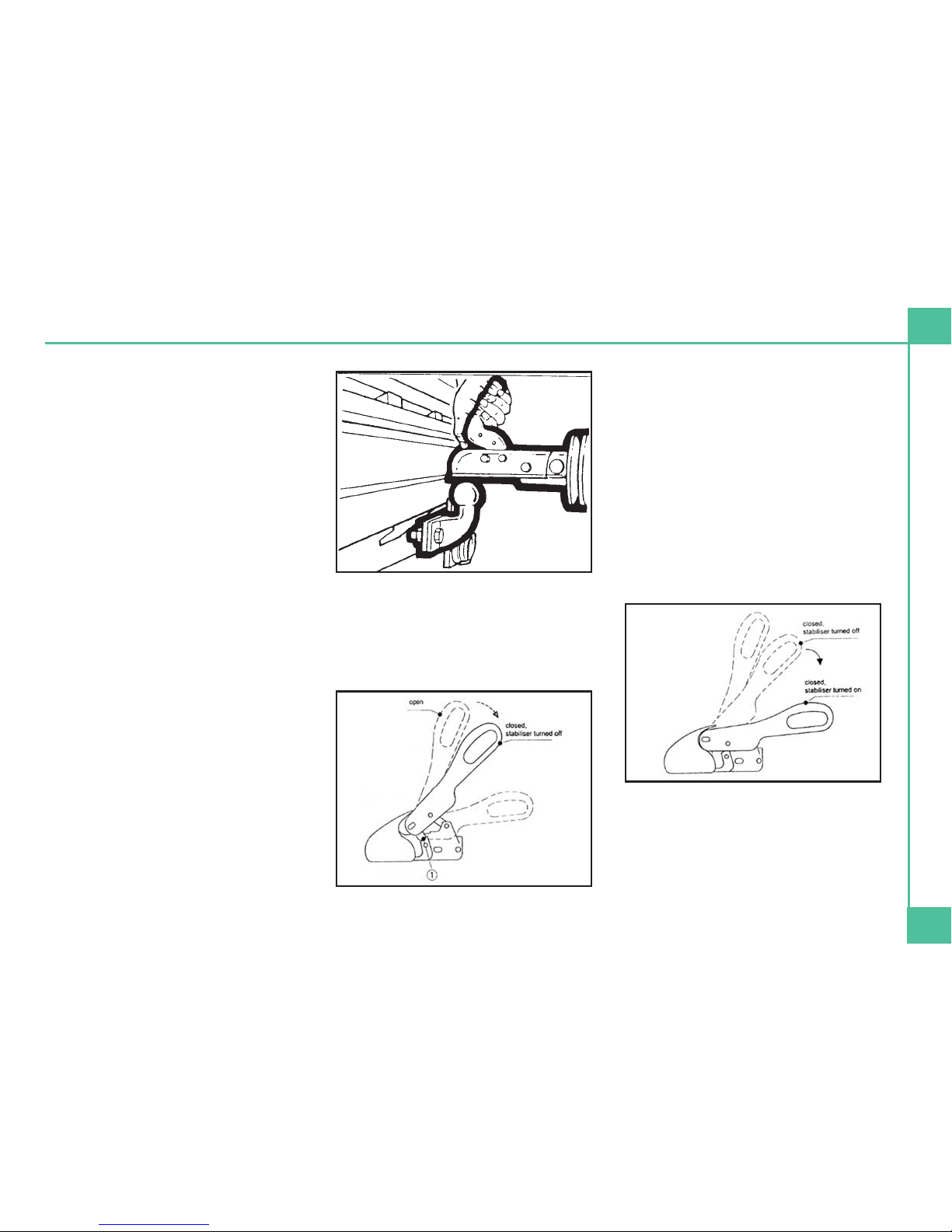
WINTERHOFF STABILISER - HITCH
HEAD OPERATION
Coupling - The opened ball coupling is
placed on the coupling ball of the towing
vehicle
The support load and possible additional
loading of the drawbar serves to cause
the ball coupling to close automatically
and the side securing lugs (1) are parallel
in relation to the securing surfaces on the
housing
Activating the stabiliser - Here, the
operating lever must be pushed down out
of its closed position to the stop. In doing
so, the spring assembly which generates
the pressing force via the friction pads
onto the ball coupling is tensioned. Upon
completion of this operation, the
operating lever is roughly parallel to the
axis of the drawbar. It is possible to drive
with the stabiliser deactivated, for
example, when manoeuvring.
Preparing for the Road
Explorer Group 2005 Touring Caravan Handbook
7
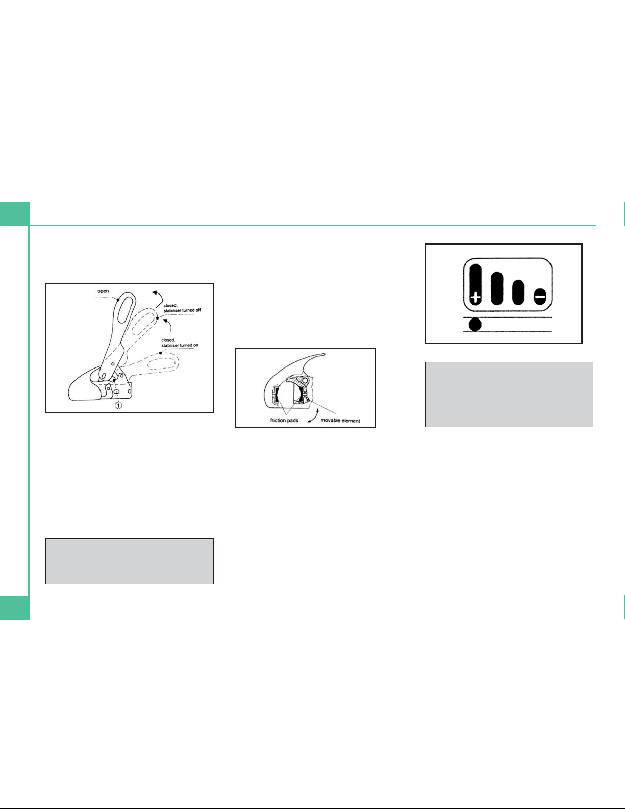
Switching the stabiliser off - Pull the
operating lever slowly upwards in order to
turn off the stabiliser.
Disconnection - Disconnect the lighting
plug and contact-breaking cable turn off
stabiliser, simultaneously pull back and lift
the operating lever such that the side
securing lugs swing over the securing
surfaces and the operating lever can be
moved to the open position. The caravan
can now be uncoupled from the towing
vehicle with the aid of the jockey wheel.
If not used for any lengthy period of time
the caravan should be parked with the
ball coupling closed. For this purpose, lift
up the open operating lever and at same
time pull the ball socket (movable element
with friction pad (Fig 8 Arrangement of the
Friction Pads - BPW Booklet) forward or
press the safety ball into the ball space
and slowly close the operating lever.
Checking the stabiliser - When the
caravan has been hooked up and the
stabiliser activated, the condition of the
friction linings can be checked. The wear
indicator located on the top of the
operating lever displays a bar graph
marked with + and - symbols. The ball
coupling is set at the factory such that the
pin visible in the oblong hole is positioned
under the + symbol on the bar graph
when new friction pads have been fitted.
ONCE THE HITCH HEAD IS CLOSED:
• Inspect the hitch. The hitch jaw must
fully enclose the ball-head and be
locked. Check the coupling head
fastenings at regular intervals for firm
seating.
• Wind up the jockey wheel until the
wheel supports locate into the cut out
sections at the base of the winding
section.
• Raise and secure the jockey wheel
using the clamp. The jockey wheel
Please note: The WS3000 ball
couplings can be locked both in
coupled and disconnected condition
with the ROBSTOP WS3000 by using
the hole on the side of the housing.
Note: when uncoupling, the overrun
device must be released i.e. the
bellow is stretched.
8
Preparing For The Road
should be parallel to the direction of
travel at all times (locate the jockey
wheel into the cut out provided in the aframe faring).
• Secure the breakaway cable to the
traction vehicle.
WARNING: The 'break-away' cable must
be secured around the towing bar
assembly and not round the ball-head.
USE OF YOUR CARAVANS
BREAKAWAY CABLE
UK LAW requires that all caravans with
brakes (e.g. caravans, horse boxes, car
transporters etc), built on or after 1st
October 1982, are fitted with a safety
device to provide protection in the unlikely
event of the separation of the main
coupling while in motion. It's also a legal
requirement to use the breakaway cable
whenever it's provided.
The purpose of the breakaway cable is to
apply the caravan's brakes if it becomes
separated from its towing vehicle. The
cable assembly is designed to part,
allowing the caravan to come to a halt
away from the towing vehicle.
Construction - Usually a thin steel cable,
possibly plastic coated, and fitted with a
means of attachment to connect to the
towing vehicle.
Operation - The cable should be able to
pull tight to engage the caravan's brakes
without any hindrance to its action, if the
main coupling of the caravan separates
from the towing vehicle. It should never
become taut during normal use.
CORRECT PROCEDURE FOR USE:
• Check cable assembly for damage. If
in doubt contact your dealer or service
agent.
• Make sure the cable runs as straight as
possible, and goes through a cable
guide underneath the caravan
coupling.
• Determine whether or not you have a
designated attachment point (a feature
of the tow bar which has been
identified by the tow bar supplier as
being for the attachment of a
breakaway cable).
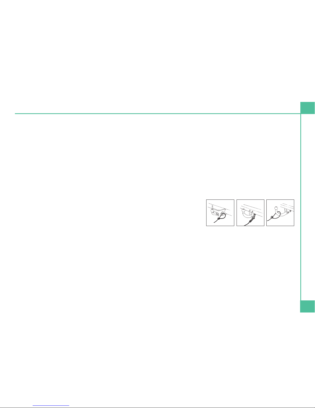
WHERE A DESIGNATED
ATTACHMENT POINT IS PROVIDED
ON THE TOW BAR
• Pass the cable through attachment
point and clip it back on itself (Figure 1
below); or
• Attach the clip directly to the
attachment point (Figure 2 below).
Note -this must be specifically
permitted by the caravan
manufacturer's guidance as the clip
may not be sufficiently strong.
WHERE NO DESIGNATED
ATTACHMENT POINT IS PROVIDED
ON THE TOW BAR
FIXED BALL - loop the cable around the
neck of the tow ball. If you fit the cable
like this use a single loop only (Figure 3
above).
DETACHABLE BALL - You must contact
the tow bar supplier for advice.
Preparing for the Road
Explorer Group 2005 Touring Caravan Handbook
9
Fig. 1 Fig. 2 Fig. 3

OTHER MEANS OF ATTACHMENT
Alternatively, it may be possible to attach
the cable assembly to a permanent part of
the tow bar structure with the approval of
the tow bar supplier, or to an accessory
sold for the purposes of breakaway cable
attachment.
WHEN THE BREAKAWAY CABLE IS
ATTACHED CHECK TO ENSURE
• That the cable cannot snag in use on
the caravan hitch, jockey wheel or any
accessories e.g. a stabiliser, bumper
shield, cycle carrier etc.
• That there must be sufficient slack in
the cable to allow the towing vehicle
and caravan to fully articulate without
the cable ever becoming taut and
applying the brakes.
• That it is not so slack that it can drag on
the ground. Leave it too loose, and the
cable may scrape along the ground,
and be weakened so that it fails before
doing its job!
• Plug in the electrical connections from
the tow car.
• Ensure that the correct vehicle licence
/ registration plate is attached to the
rear of the touring caravan.
• Check that all tail-lights, brake lights,
road lights and indicators work
correctly.
• Release the parking brake on the
caravan and adjust all rear and side
view mirrors from the driving seat
before setting off.
For peace of mind, you may wish
to check the state of the cable by
positioning the caravan and
towing vehicle at extreme angles
before setting off.
If having followed this advice, you
feel you cannot achieve a
satisfactory cable arrangement,
consult your caravan or tow bar
supplier or service agent.
10
Preparing For The Road

TOWING AND DRIVING
Please also refer to The Caravan Towing
Code which is included in your Owner’s
Information Pack.
REVERSING
It is advisable to have a second person
available when reversing the caravan.
Start practising by choosing a left-hand
bend for ease. Reverse slowly, turning the
wheel, initially the opposite way to the
direction you want the caravan to go.
Now the front of the caravan is nudged
out and is moving the rear in the intended
direction. Take care not to hit the van with
the car!
Midway through the manoeuvre, when
the caravan is correctly angled, slow to
crawl and gradually apply opposite lock.
Make the car follow the caravan round
then finally straighten up.
Proficiency at reversing can only be
achieved with practice.
SPEED LIMITS
Normal road towing: 50mph
Motorways (including dual
carriageways): 60mph
SETTING OFF
Let the clutch in smoothly.
Allow more engine speed to produce the
power to move the additional weight of
the caravan.
Avoid wear and tear on clutch and
transmission by taking extra care.
Change gears smoothly.
Try not to jerk the clutch.
CARAVAN HANDLING
Allow for the caravan being wider than the
car. Do not bump kerb with caravan
wheels.
When passing other vehicles, allow more
than the normal clearance for driving solo.
Allow longer to get up speed to pass.
Allow for the vehicle being twice its
normal length. Do not suddenly swing
out.
Carry out all manoeuvres as smoothly as
possible.
Use nearside wing mirror to check
caravan has cleared when overtaking.
Preparing for the Road
Explorer Group 2005 Touring Caravan Handbook
11
12
Site Arrival
SITE ARRIVAL
CHECK SITE REGULATIONS
On arrival at a camp site, you should
always check the site regulations. This
will help avoid any unnecessary conflict
with site management and other site
users.
SELECTING A PITCH
Carefully select where you wish to place
your caravan. The site should be as level
as possible, preferably not under or near
trees, well drained and away from
possible boggy areas. Consider how you
will move the caravan when it is time to
leave the site. On sloping ground it is
better to pitch facing downhill, especially
during wet weather.
SIDE TO SIDE OR LATERAL LEVELING
A quick glance at your pitch should tell
you if you are likely to need side to side
leveling i.e. leveling across the axle.
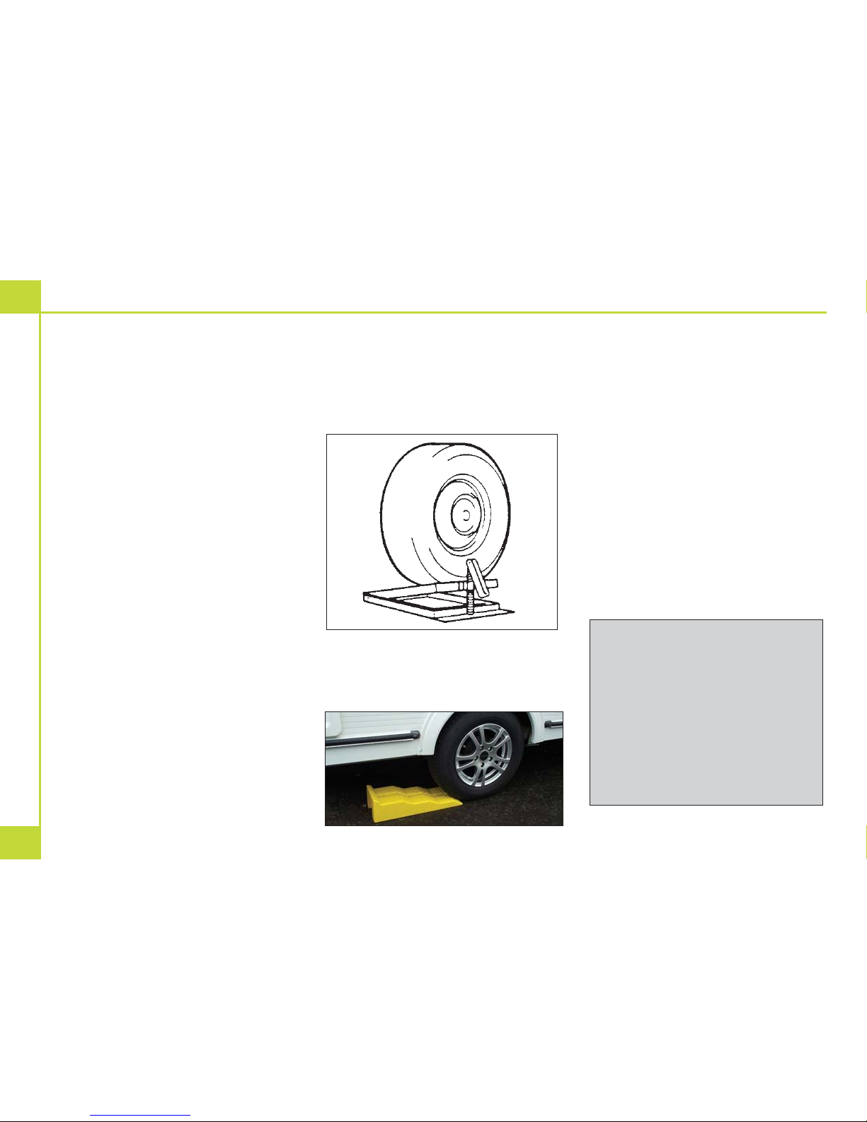
On uneven ground lateral levelling is
accomplished by the use of a leveller jack
or ramp and a spirit level placed 'across'
the caravan floor.
Leveller Jack - Place the leveller jack,
folded flat, in front of the wheel needed to
be raised to level the axle. Tow the
caravan onto the leveller jack and adjust
the height until the spirit level shows that
the caravan is laterally level.
Ramp - Reverse onto your pitch about a
foot further back than you wish to end up.
Then place the leveling ramp in front of
the wheel that needs to be raised.
Place a spirit level parallel to the axle on
the A-frame or just inside the caravan
door. It helps to have two people at this
point. One should drive the car very
slowly forward moving the caravan wheel
up the ramp, and the other should
indicate when the spirit level bubble is in
the middle.
Whichever method you use, once level,
apply the caravan handbrake and chock
the caravan wheel if necessary. Lower the
jockey wheel to ground level before
unhitching. (See index uncoupling)
You should then park your car, usually
next to the caravan furthest away from the
door side.
(On upward facing pitches when the
hydraulically damped drawbar of the
hitch becomes fully extended, it will
be necessary to compress the
drawbar slightly in order to achieve a
'clean' unhitching). With the caravan
brake on, reverse the towing vehicle
about 2.54cm (1 inch) to release hitch
lock tension and using the jockey
wheel adjustment, unhitch the
caravan as previously described.
Explorer Group 2005 Touring Caravan Handbook
13
FRONT & BACK OR FORE & AFT
LEVELING
This should be done only when the lateral
leveling is complete.
Place the spirit level pointing front to back
just inside the caravan door or on the Aframe, then raise or lower the jockey
wheel until the caravan is horizontally
level.
If there is a significant front to back slope,
you may need to place a block under the
jockey wheel.
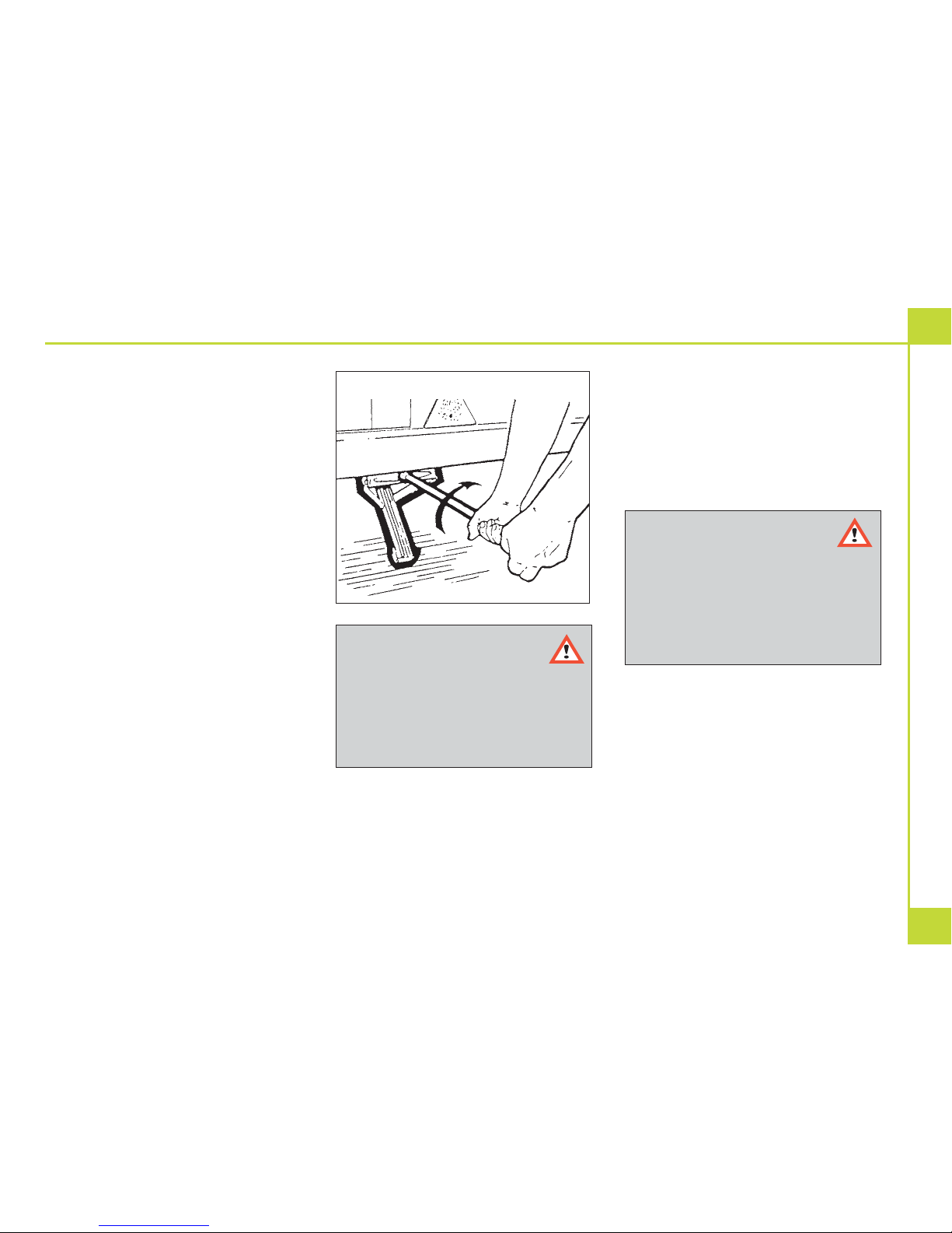
Next, wind down the corner steadies onto
load spreaders (blocks of wood a
minimum of 15.25cm (6 inches) square or
'Big Foot' steady attachments) until they
are firmly set against the ground. It is
possible on very uneven sites that when
fully extended blocks may be required
under the corner steadies to achieve this.
It is important that the caravan is correctly
levelled to ensure the correct working of
the refrigerator, cooker etc.
Now that your caravan is level, place the
caravan step in front of the door ensuring
that it is stable and safe to use.
PARKING ON A REVERSE-SLOPING
SITE OR STEEP HILL
For successful parking on a reverse slope
or steep hill, the operator need only apply
the handbrake with one hand while gently
but purposely inching the caravan a small
distance backwards with the other.
WARNING:
If the handbrake is NOT fully
applied to the last tooth (i.e. vertical)
and is set to some lesser position
than the full vertical, then problems
will almost certainly arise after the
caravan has been uncoupled from
the towing unit.
CAUTION: Never enter the
caravan without first lowering
the four corner steadies with the
brace provided.
Corner steadies should not be used
as a jack. Take care not to lift the
caravan wheels.
Site Arrival
14
Connecting Services
WATER
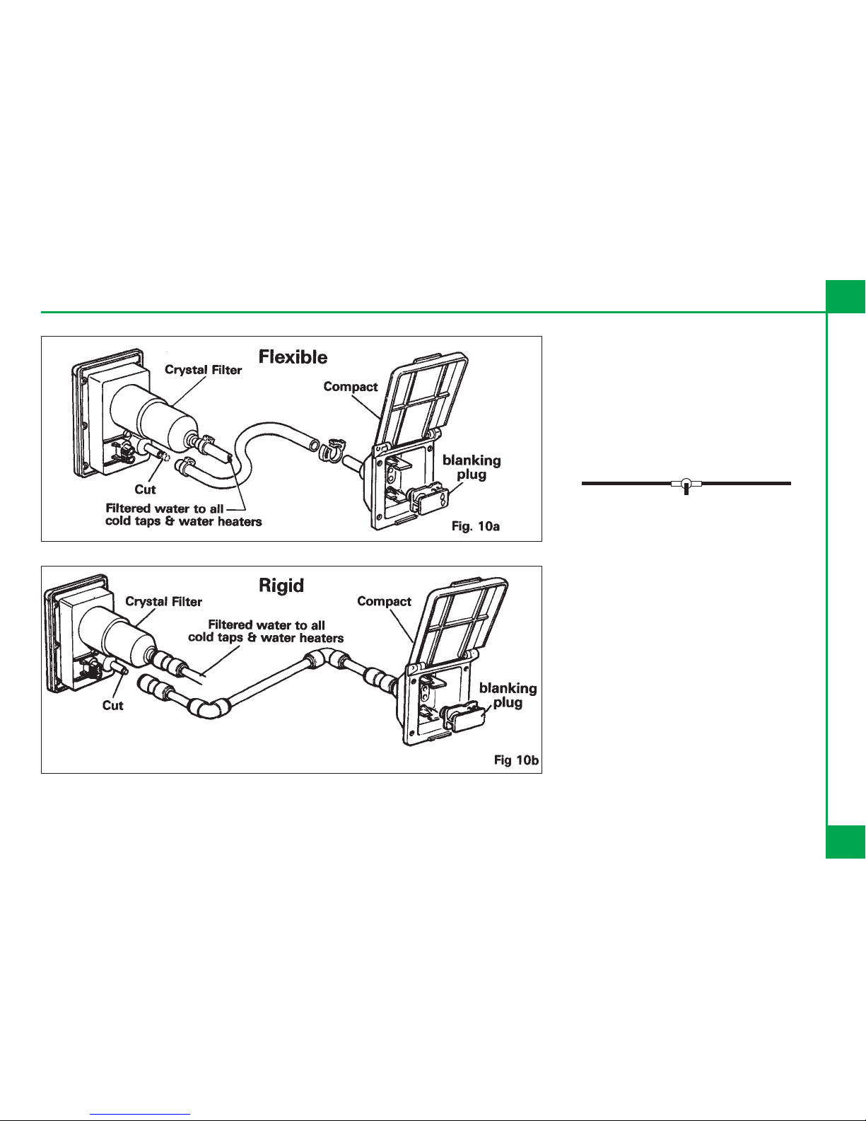
Your caravan will be supplied with either a
Truma Crystal or a Truma Compact water
inlet and submersible water pump (refer
to Equipment Lists section to confirm).
Follow the relevant instructions below to
connect a water supply to your caravan.
Once you have filled your fresh water
container e.g. Aquaroll, from a suitable
water supply, return to the caravan and
stand the water container upright close
enough to the water inlet.
Place a suitable waste water container
e.g. Wastemaster, under the main drain
outlet.
Remove the container's sealer cap and
put in a safe place - not on the ground as
this may contaminate your water supply
the next time you use it, and place the
submersible pump into the fresh water
container, ensuring it is fully submerged
before operating the system.
For information on using a waterline with
an onboard tank see index.
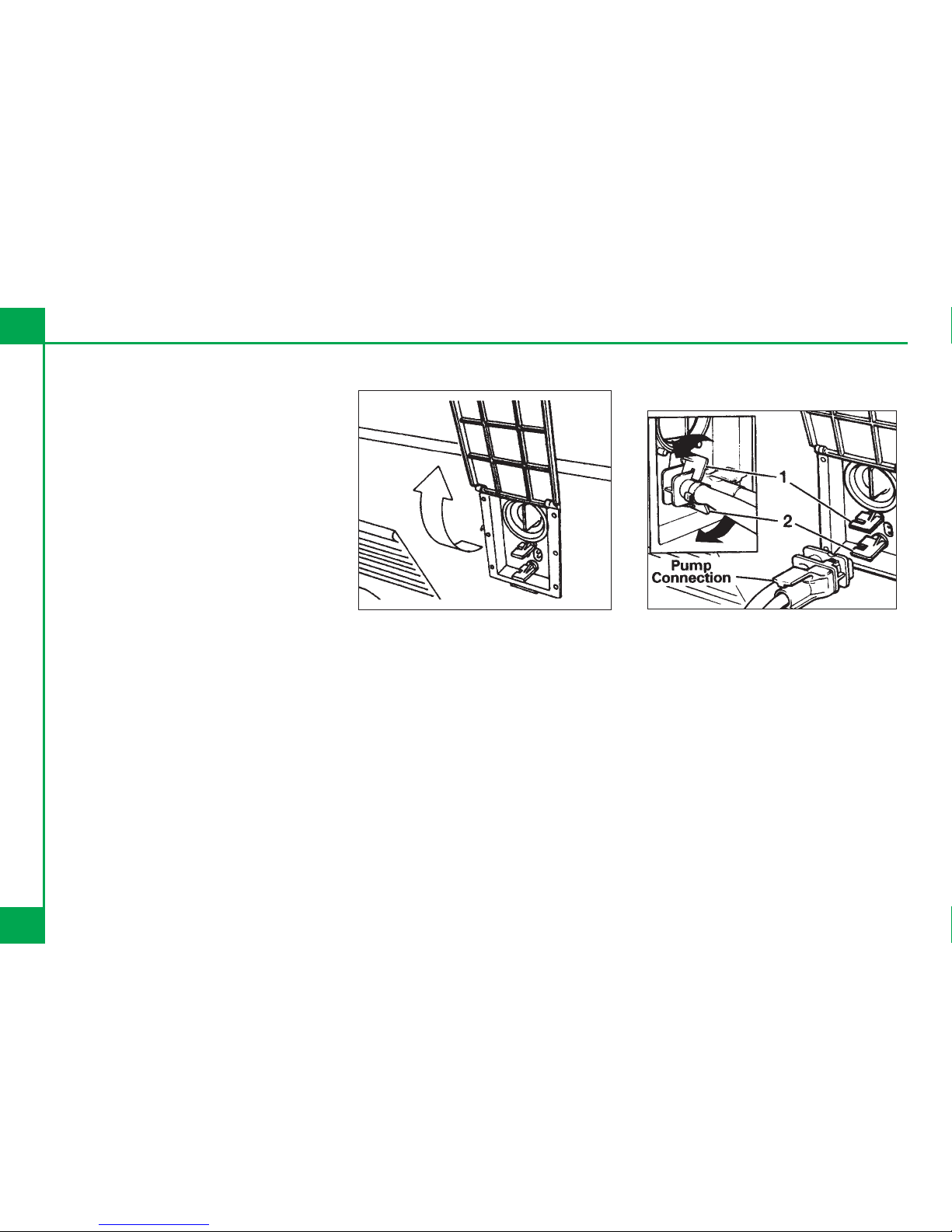
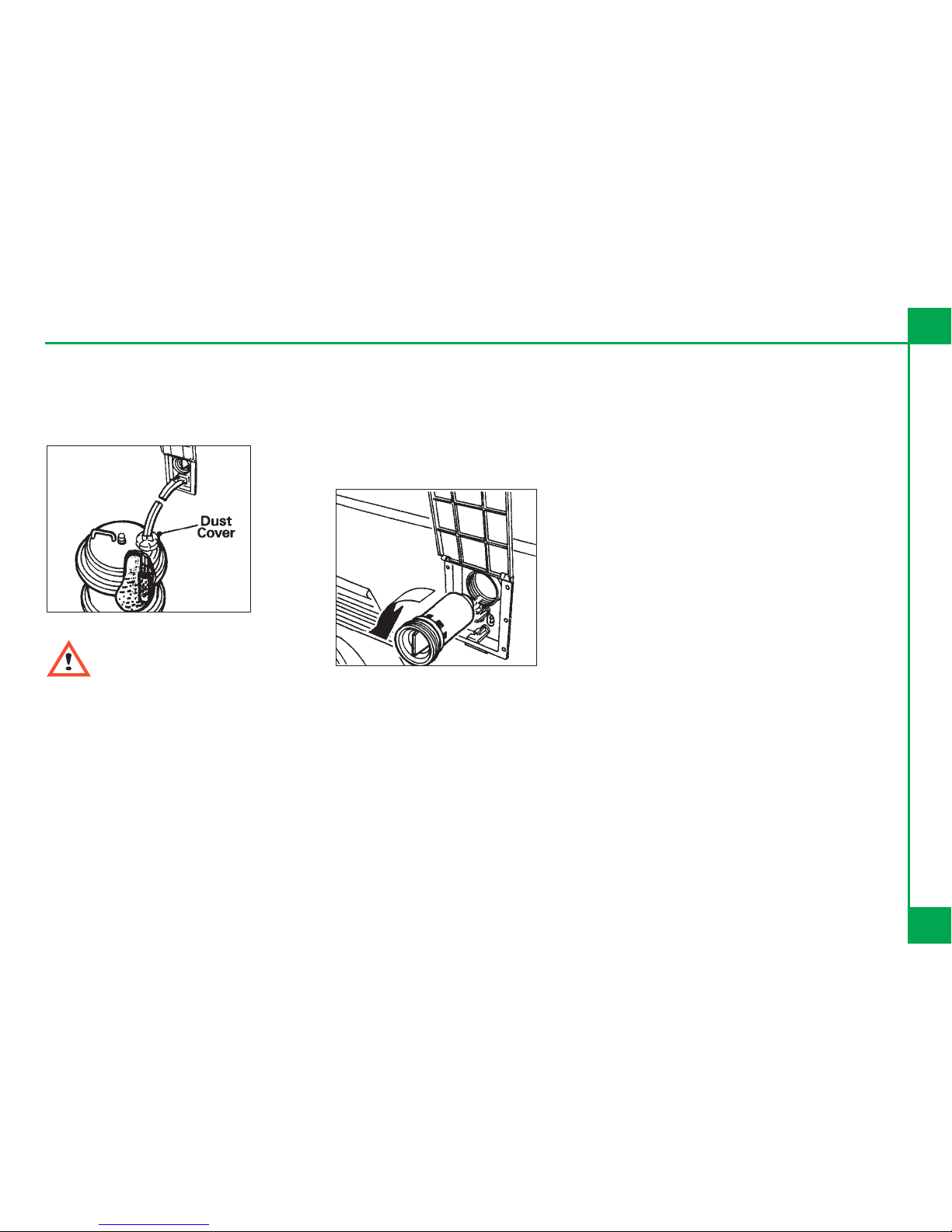
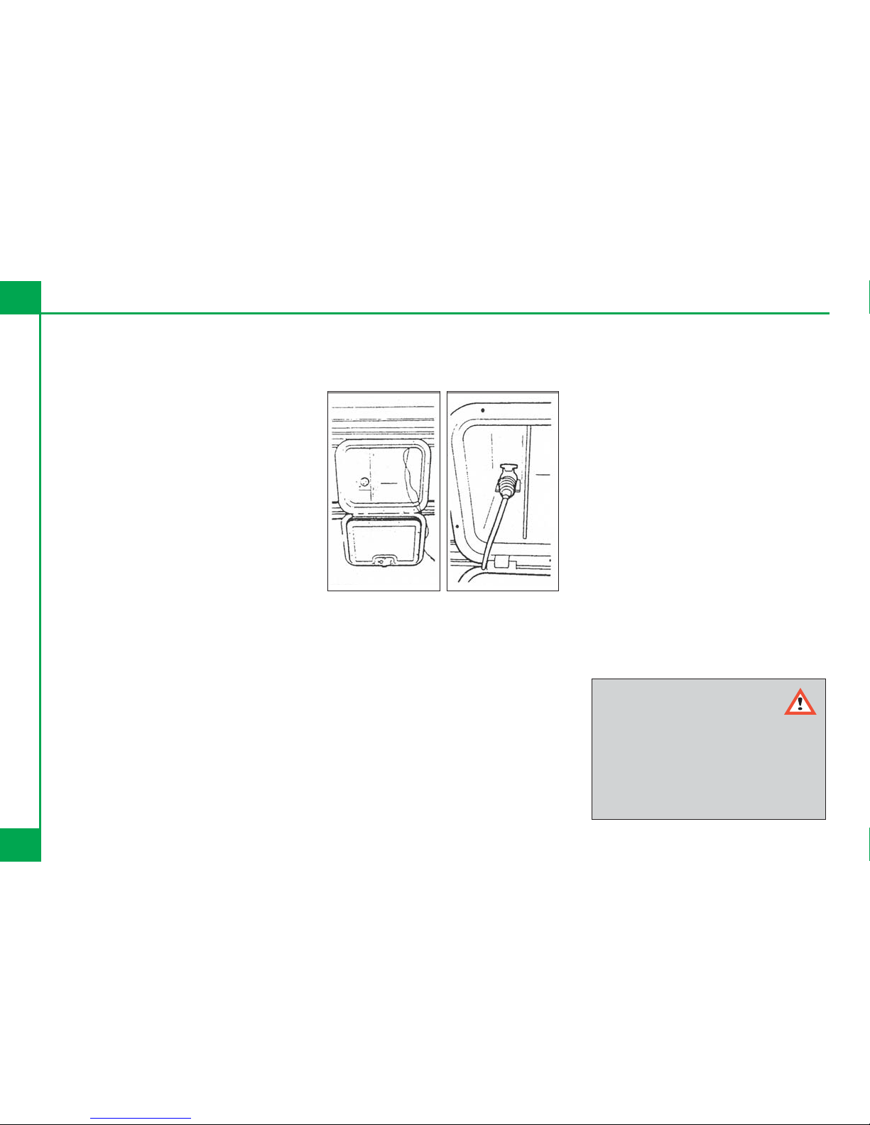
WATER PUMP CONNECTION
RAISE THE LID AND CLEAN BOTH THE
WATER SOCKET AND THE PLUG OF
THE PUMP ASSEMBLY.
Align the plug and push the pump
assembly into the socket. This makes
both the water and electric connections.
Turn the top security clip anti-clockwise
and the bottom security clip clockwise to
lock the plug into place.
The pump system has been designed so
that it can not be fitted incorrectly.
Prior to operation of the water heater,
ensure water is flowing from the hot tap.
Finally put the 'pump' switch on the
control panel to 'on' and turn the cold tap
on until water flows.
To remove the pump assembly from the
water inlet, release the security clips and
pull the hose adaptor by using the finger
grips provided.
Do not remove by pulling the
hose or electric cable.
TRUMA CRYSTAL ROUTINE
MAINTENANCE
1. Ensure that the 0-ring seal on the hose
adaptor and socket are free from dirt.
2. To aid fitting of the plug assembly
smear the 0-ring with vegetable oil.
3. To help protect the electrical
connections smear both the male and
female terminals with petroleum jelly.
4. To change the filter cartridge. Turn the
cartridge anti clockwise to remove.
5. Ensure that the new cartridge is fully
tightened in the holder. If the cartridge
is difficult to fit smear the ring with
vegetable oil.
TRUMA CRYSTAL STERILISING
a. When cleaning the Water system at the
start or the end of the season it is
advisable to use a sterilising fluid e.g.
Chempro SDP or similar. It is
recommended that for this operation
an old filter is fitted as the fluid reduces
the effectiveness of a now filter.
b. Flush the system thoroughly to remove
the effective fluid traces.
c. After sterilising the system at the start
of the season it is recommended that a
new filter cartridge should be fitted
TRUMA CRYSTAL FILTER CARTRIDGE
1. After fitting a new filter cartridge it is
recommended that the system is
flushed through for approx. 30
seconds to remove any harmless
particles of carbon,
2. It is suggested that the filter cartridge
should be replaced after approx. 30
days of caravanning. After such time
the carbon filter will become less
effective,
3. Always ensure that the filter cartridge is
fully tightened in the holder. If fitting of
the new filter cartridge is difficult smear
the 0-ring with vegetable oil.
Connecting Services
Explorer Group 2005 Touring Caravan Handbook
15

TRUMA CRYSTAL - HOW TO
PREPARE YOUR WATER SYSTEM FOR
WINTER USE
During winter caravanning it is desirable
to keep the water container within the
caravan to prevent freezing. This can be
achieved by fitting a Compact Housing
unit inside the caravan in a location where
it is convenient to store a Container, e.g.
the washroom or under the sink etc.
This should only be done by an Approved
Explorer Retailer or Service Centre as
your warranty will be affected.
TRUMA CRYSTAL - NOTES
1. Never allow the pump to run dry.
Always ensure that the pump is
submerged in the water or the life of
the pump will be reduced.
2. Before winter storage the water system
must be completely drained and the
filter cartridge removed to avoid any
retained water within the filter freezing.
The filter hole may be sealed with an
old filter end cap or left open but do
ensure that the lid is firmly closed.
See Index - Draining Down The Water
System.
3. Clean the water system at the start
and end of the season with
sterilising fluid (see notes under
sterilising).
4. If the pump fails to deliver water the
most likely cause will be air in the
system. Switch off the pump and
shake the pump assembly in the water.
Then switch on again. And/or the filter
cartridge is not fully tightened. Ensure
that the filter cartridge is screwed fully
into its holder.
16
Connecting Services
Connecting Services
Explorer Group 2005 Touring Caravan Handbook
17
HOW TO USE A WATERLINE WITH
THE INBOARD WATER TANK
1. Place the pump switch on the control
panel to the 0 position.
2. Place tap next to the tank into the
centre position. See diagram below.
Pipe Tap Pipe
3. Connect waterline to water inlet on side
of caravan.
4. Turn on waterline
5. While the waterline is in use the pump
switch on the control panel must
remain in the 0 position.
6. Ensure that you return the tap next to
the tank to the inline position when you
wish to return to using the inboard
tank.

DRAINING DOWN YOUR WATER
SYSTEM
1. It is essential that you drain down your
caravan water system when it is not in
use. This is most important during
winter months to protect against frost
damage.
2. Disconnect the water pump and
switch of power supply.
3. Remove the water heater fuse from
the switch spur and store in a safe
place.
4. Open the safety drain valve on the
water heater located next to the water
heater.
5. Open all taps and remove all plugs
from sinks and showers. Lever
operated taps should have the lever
put into the up position.
6. Open the drain outlets on the outside
of your caravan.
7. If an inboard water tank is fitted ensure
that the drain tap on the tank is open.
8. Adjust the level of the caravan to
ensure that the drain outlet is at the
lowest point of the caravan. This will
aid the flow of water to ensure all
water is drained off.
9. After 30 minutes level the caravan and
prepare it for storage if necessary.
18
Connecting Services
GAS
Your caravan is designed to operate using
either propane or butane liquefied
petroleum gas at 30M/bar. Gas can be
obtained from your caravan dealer.
Your caravan is designed to accept a
maximum 2 x 7.5kg gas bottles.
TYPES OF GAS
BUTANE
Butane is supplied in the U.K. in Green or
Blue bottles.
All these have a male left hand thread
except for Camping Gaz, which has a
special female right hand, Calor 7.5 kg
bottles have a special clip-on connection.
Continental bottles usually have a male
left hand thread which is similar, but not
identical, to UK butane.
Butane is suitable for use at temperatures
down to 2°C but will not work below that.
PROPANE
Propane is supplied in red, or partly red
bottles which have a female left hand
threaded connector.
Scandinavian countries use the same
connector.
Germany or Austria supply propane with
a male connection.
Propane will work at temperatures as low
as –40°C and is therefore suitable for all
winter caravanning.
CONNECTION
Make sure that heating and cooking
appliances and gas cylinders are
switched off.
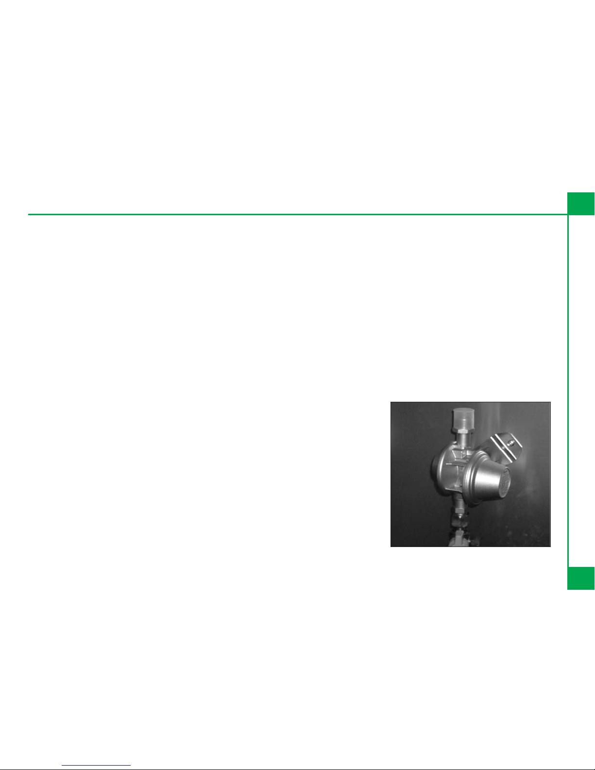
Your new Explorer Group Caravan has
been fitted with a fully approved gas
regulator designed to operate at a gas
pressure of 30Mbar. Your regulator is
fitted with a test point, which is accessed
via the inlet at the side of the regulator.
This access point is only for carrying out
gas pressure tests and should not be
used for any other purpose.
It is strongly recommended that only
CORGI approved gas fitters carry out any
work on your caravan's gas installation.
HOSES
You should only connect to this regulator
using an approved high-pressure hose of
length not exceeding 450mm from the
gas cylinder to the regulator. These
approved high pressure hosed are
available from your Explorer Group
Retailer. These hoses are connected
using screw thread fittings, which will
make a seal if connected and tightened
using a spanner.
Connecting Services
Explorer Group 2005 Touring Caravan Handbook
19
Each gas Appliance is connected to its
own gas isolation tap. These are identified
on the tap via a label. Below is a key to
identify each label. To operate the tap the
Arrow on the tap shows the direction of
flow for the gas. The arrow should be
pointing towards the appliance for the
appliance to operate. There will be a small
label next to the bank of taps under the
cooker which is also reproduced below:
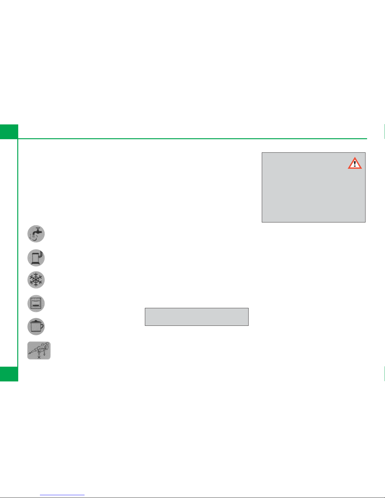
Water Heater
Space Heater
Fridge
Cooking Appliance
Hob
Gas On/Off
GAS SAFETY ADVICE
In the event of a suspected gas leak the
gas must be turned off using the isolation
valve on the gas bottle. A Competent gas
Fitter should then check the system
before it is used reused.
Regularly check flexible gas hose, joints
and connections for tightness. Finally,
make sure that each gas appliance is
working efficiently to the
recommendations of the appliance
manufacturers.
See Index - Ventilation
FACTS ABOUT LPG
LPG is not poisonous.
Bi-products are harmless.
LPG is dangerous if all air and oxygen is
excluded.
LPG has been given a smell by the
manufacturers in order to identify leaks.
The gas is heavier than air and therefore
sinks to the lowest point.
AWNING SPACES AND LPG
APPLIANCE EXHAUST
There is no danger of pollution of an
enclosed awning space from the LPG
exhaust from a refrigerator venting into it.
Space heaters may produce sufficient
exhaust to pollute the awning space, if it is
totally enclosed, from a general comfort,
smell and hygiene point of view. In
extreme cases there could be a build up
of carbon dioxide to a dangerous level.
Caravan owners are advised to allow
some fresh air circulation in the awning
space when such appliances are in use.
WARNING:
Aerosols and highly flammable
liquids must not be stored in the
compartment behind, or adjacent to,
any gas appliance.
Some industrial LPG appliances
operate at high pressure and require a
‘high pressure’ regulator. This often
has an adjusting handle on it. NEVER
use such a regulator on a caravan.
(Ventilation holes must be clear at all
times).
20
Connecting Services

LPG GAS SYSTEM
The Explorer Group does not recommend
the use of any external cylinders. All
cylinders in use should be within the gas
locker provided. If you wish to utilise a
larger cylinder and have this outside the
gas locker then the connecting hose must
not exceed 750mm.
It is recommended that no flammable
material is stored or placed with 300mm
of any open flame. Your attention is also
drawn to the fact that the surface of the
Space Heater in your caravan will get hot
when in use.
You are advised not to use any additional
gas appliances outside your caravan
unless it is a Gas Bar-B-Q connected via
the Bar-B-Q point supplied with your
caravan.
Please ensure that you have read the
operating instructions for each gas
appliance contained in your Owners
Information Pack.
Please ensure that any gas hose left
unconnected is protected from dirt or
other foreign bodies entering the hose.
GAS BARBECUE POINT
Your caravan may be fitted with a gas
barbecue point.
The gas barbecue point, when fitted, is
situated on the nearside towards the front.
This point is for use with a gas barbecue
only.
Simply lift up the flap, unplug the red
plastic end cap and connect the
appliance in accordance with the gas
barbecue manufacturer's instructions.
CAUTION! Do not use a gas barbecue
inside the awning.
ALWAYS use the appliance in the open
air.
There will be an isolation valve fitted next
to the Barbecue point. This is an
automatic valve, which cannot be
operated unless a connection has been
made to the Barbecue point. Do not apply
any force to this value.
Connecting Services
Explorer Group 2005 Touring Caravan Handbook
21
ELECTRICITY
ELECTRICITY MAINS SUPPLY
Your caravan's main electrical installation
is designed to run on a 230v 50hz AC
supply.
ON ARRIVAL AT CARAVAN SITE
1. Before connecting the caravan
installation to the mains supply, check
that:
(a)The mains supply is suitable for your
installation and appliances, i.e.
whether it is AC or DC and whether it is
at the correct voltage and frequency.
(b)Your installation will be properly
earthed. Never accept a supply from a
socket outlet or plug having only two
pins, or from a lighting outlet.
(c)Any residual current device (earth
leakage circuit breaker) in the mains
supply to the caravan has been tested
within the last month. In case of doubt,
consult the site owner or their agent.
2. Make sure that the switch at the site
supply point is off and that all electrical
equipment in the caravan is switched
off by ensuring your caravan mains
isolating switch on the MCB is in the
'OFF' position.
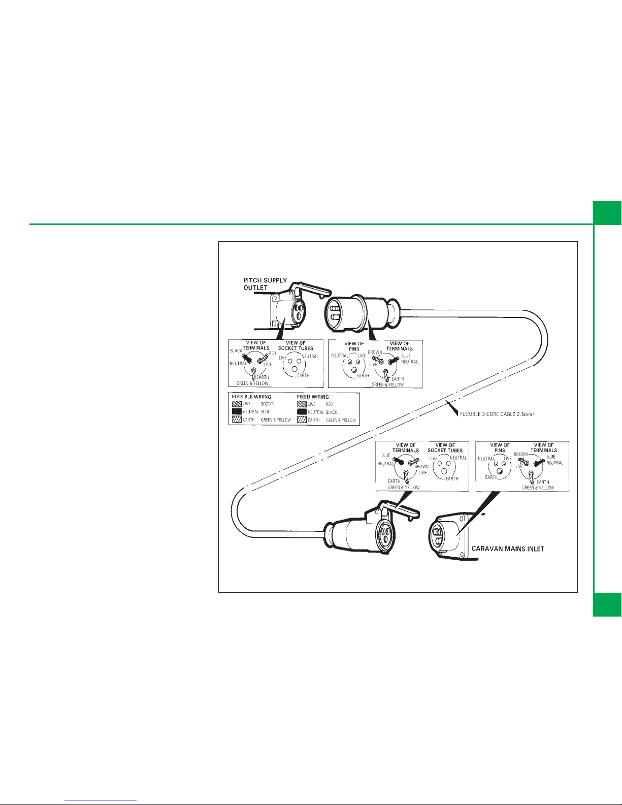
3. Remove any cover to the electricity
inlet provided on the caravan, and
insert the female connector of the
flexible orange supply cable.
4. Locate the site supply and remove any
cover from the socket outlet provided
at the supply point. Insert the male
plug at the other end of the flexible
orange supply cable. Switch on the
main switch at the site supply point (if
appropriate).
5. Place any surplus cable under the
caravan. Ensure that the surplus cable
is not coiled up as it could overheat.
6. The MCB main electricity supply switch
should be put in the 'ON' position.
7. Check the Residual Current Device is
working be pressing the test button.
Reset, and then check the refrigerator
and water heater are switched to mains
operation.
ON LEAVING CARAVAN SITE
1. Switch 'OFF' at the caravan mains
isolating switch.
2. Remove the male plug from the site
supply.
3. Disconnect the female plug from the
caravan and store the cable in an
appropriate locker.
Electrical Warning.
Attention: Always disconnect
the electrical connector between the
towing vehicle and the caravan
before connecting a Mains (LV)
supply to the caravan and before
charging the caravan battery by any
other means.
22
Connecting Services
OVERSEAS ELECTRICAL
CONNECTION
NOTE: Connection to a mains voltage
supply OVERSEAS requires particular
attention.
Care must be taken when connecting
supplies abroad since the supplies can
be of REVERSE POLARITY. The
significance of REVERSE POLARITY is
that when equipment is switched off, it
may not be electrically isolated. The only
certain way of making equipment safe is
to unplug it. A means of checking the
polarity of the mains supply when
overseas is useful.
There are available several proprietary
makes of equipment for the purpose. If it
can be achieved, it is preferable to
connect live to live, and neutral to neutral
to maintain full electrical protection.
CHECK all caravan equipment is set-up to
accept the site supply before actually
switching on.
Connecting Services
Explorer Group 2005 Touring Caravan Handbook
23
MALE CABLE PLUG
FEMALE CABLE
COUPLER
BATTERY INSTALLATION
If you wish to install a leisure battery
please ensure that it is placed on the
battery tray supplied with your caravan.
Then place the tray in the battery locker
fitted to the side of your caravan. Connect
the battery to the clamp fittings connected
to the connection leads within the battery
box. The Explorer Group recommends
that you use sealed for life leisure
batteries of a minimum rating off 40
ampere-hours at 20h discharge rate.
BATTERY MAINTENANCE
Your leisure battery should be maintained
in accordance with the manufactures
instructions. For information on the
automatic charging system in your
caravan please refer to 'Automatic
Charging System' in the index.
Do not charge your leisure battery with
any charger other than that supplied.
Failure to comply may cause damage to
your battery.
If you remove your leisure battery, ensure
that it is not placed on a cold surface as
the battery will deteriorate more rapidly
than if stored at a suitable temperature
GENERATORS / CHARGER
All electrical equipment fitted in your new
caravan can be run from either a
controlled generator or charger whose
output is maintained between 11v and
14v.
At least once every 3 years, the caravan
electrical installation should be inspected
and tested, and a report on its condition
obtained, as prescribed in the
Regulations for Electrical Installations,
published by the Institute of Electrical
Engineers.
MAINS UNIT
The Mains Unit replaces the conventional
fusebox. Similar, but larger ones are often
fitted in new houses. The unit gives
overload and earth leakage protection for
the 230v electrical supply in your caravan.
For normal operation all switches on the
unit need to be in the ON position. The
switches on the left of the unit are known
as MCBs (miniature circuit breakers).
These take the place of the conventional
fuse but are more convenient.
In the event of a fault the MCB 'trips' i.e.
automatically moves to the OFF position.
After elimination of the fault the MCB can
be re-set by switching to the ON position
(against the spring pressure in an
upwards direction).
If an earth fault develops, or a person was
to touch a live piece of equipment, the
leakage of current to earth should
immediately operate the RCD (residual
current device) and 'trip' the main switch,
to the OFF position.
This switch is only re-settable after
elimination of the fault.
In case of difficulty, consult
an approved electrical
installation contractor (who may
be the local electricity board). It is
dangerous to attempt
modifications and additions
yourself.
Lampholder-plugs (bayonet- cap
adaptors) should not be used
under any circumstances.
24
Connecting Services

RESETING THE RCD
To re-set, operate the switch as for MCBs.
Periodically the RCD should be checked
by operating the test button marked 'T'.
The unit should immediately switch to the
OFF position. If the unit does not switch
off then a qualified electrician should be
consulted.
If the unit does switch off, the test is
complete and the switch can be re-set
restoring the supply back to normal.
NOTE:
It is possible that all of the 230V mains
electrical equipment may not be able to
be operated simultaneously. A typical UK
caravan site mains hook-up point
provides a maximum output of 10 amps
and on some continental sites the
available output may be as low as 5
amps. If your loading exceeds the site
supply it may trip the site circuit breaker.
Please check the available mains output
with your site operator.
The following items need to be added
together if used simultaneously. 230V
Mains equipment typical consumption
figures:
• Fridge 0.50 amps
• Charger 0.50 amps
• Water heater 3.9 amps
• Blown air heaters 8.5 amps
• Colour TV 2.50 amps
• Microwave 10.00 amps
• Air conditioning 4.00 amps
• Your caravan will be fitted with a Power
Centre II or BCA Leisure charging and
power distribution unit.
AUTOMATIC CHARGING SYSTEM
The battery charger will operate
automatically when the caravan is
connected to the mains outlet on a
caravan site. The 12V system, with the
exception of the 12V fridge and battery
charging, will not operate when the
caravan is connected to the towing
vehicle.
Connecting Services
Explorer Group 2005 Touring Caravan Handbook
25
VENTILATION
All caravans manufactured by the
Explorer Group Limited are ventilated at
both high and low level in accordance
with BSEN 721 Safety Ventilation. The
fixed ventilation points fitted in your
caravan must not be blocked under any
circumstances as your safety may
depend upon them.
It is advisable that the fixed ventilation
points are checked and cleaned (where
necessary) on a regular basis.
HIGH-LEVEL VENTILATION
This is always provided by fixed
ventilation within the fitted roof skylight.
All roof skylights fitted by Explorer Group
provide fixed free area ventilation. These
roof skylights should be cleaned annually
by use of a small brush to remove any
dust that may have accumulated around
the mesh fitted. On some roof skylights
the mesh can be easily removed to aid
cleaning. On fan-assisted roof skylights it
is essential that the roof skylight be
switched off prior to cleaning.
LOW-LEVEL VENTILATION
Low level ventilation is provided under the
front chest of drawers, except in an Lshape layout, where it can be found either
in the nearside or offside bed box. The
exact position can be identified via the
white plastic cover used to prevent the
ventilation from being obstructed. In order
to clean the ventilator, remove the cover
by undoing the two screws and clean
using a small brush. It is essential that the
cover is replaced once cleaning is
complete.
VENTILATION IN SEPARATE
BEDROOMS
In caravans with sleeping areas separated
via a solid door, separate ventilation is
required and is provided via a roof
skylight at high level and a ventilator at
low level within a bed box.
GAS DISPERSAL HOLES
All appliances and gas unions have a gas
dispersal hole nearby. It is essential that
these are not blocked or made ineffective.
Petrol/Diesel Fumes
The fitting of a tail pipe to your
exhaust will reduce the possibility of
fumes entering your caravan through
the front fixed ventilation points.
26
Safety

FIRE
FIRE EXTINGUISHERS
It is recommended that a 1 kg (2lb)
minimum capacity dry powder fire
extinguisher be carried inside your
caravan at all times. A fat pan fire must not
have an extinguisher aimed at it, but must
be smothered with a fire blanket.
IN CASE OF FIRE
1. Get everyone out of the caravan as
quickly as possible using whichever
exit is quickest including windows. Do
not stop to collect any personal items.
2. Raise the alarm. Call the fire brigade.
3. Turn off gas container valve if safe to
do so.
FIRE RETARDANT FOAMS
Under the Condition of the Consumer
Protection Act 1987, the manufacturer has
a responsibility to ensure that their
product is as safe as possible.
With this in mind all caravans are
equipped with either Combustion
Modified High Resilient (C.M.H.R.) foam
cushions or sprung mattresses. These
foams are very much safer from a fire
point of view than those previously used.
In addition all upholstery is made of fire
retardant fabric.
Fire Safety
Explorer Group 2005 Touring Caravan Handbook
27
Theft Deterrant, Prevention and Security
of Your Touring Caravan Security of your
touring caravan is taken very seriously at
The Explorer Group. That is why we have
provided a combination of standard
features and optional extras designed to
deter and prevent thieves from stealing
your property. And in the unlikely event
that they should succeed, aid the
identification and speedy recovery of your
property and assist in the prosecution of
the thief.
CARAVAN THEFT
The theft of a caravan can occur in the
most unlikely circumstances; from a
motorway service area, even from an
owner's driveway.
Secure all windows and doors when your
caravan is unoccupied, even if only for a
short length of time.
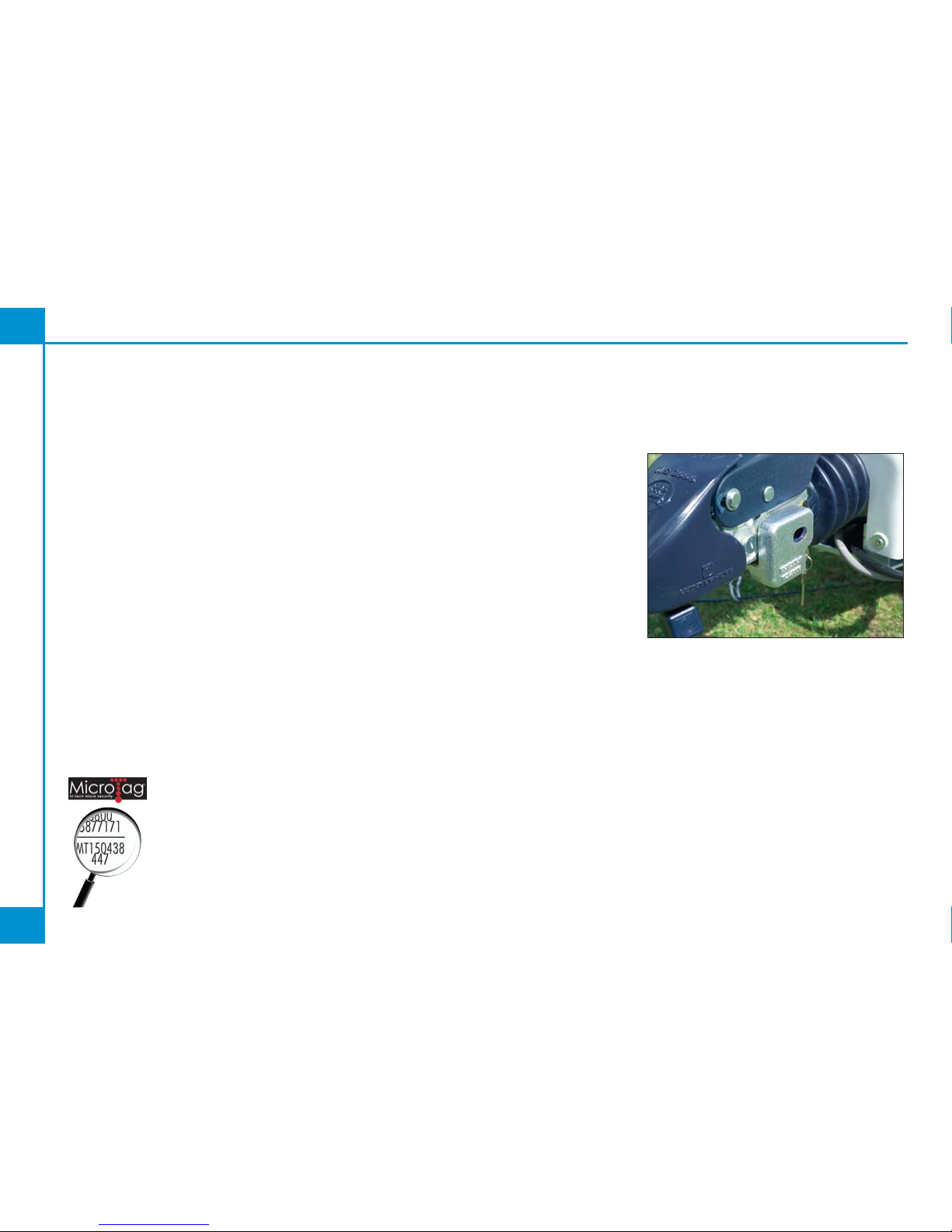
MICROTAG© NEW
Supplied as standard with
every Explorer Group
touring caravan,
MicroTag© is an innovative
and technologically
advanced property tracing
system that can be easily applied to all
your valuables. Marking your property
with Microdots not only deters theft, but
will also help lead to the successful
prosecution of the thief and the recovery
of your stolen valuables.
Why Use Microdots? - In order for the
Police to successfully prosecute, it is
necessary to identify the true owner of
stolen property. Marking your property
with Microdots is the easiest way to
ensure your valuables are quickly
identified.
You can Microdot all kinds of property
against theft including your touring
caravan, motor vehicles, televisions,
bicycles, jewellery, in fact anything of
value to you, that will also be of value to a
thief.
In the event of theft the police can locate
the MicroDot by using an ultra violet light.
The MicroDots are then read using a
MicroDot reader, or a conventional
microscope. Each MicroDot is laser
etched with a freephone helpline and your
own unique number which is registered
on the International Security Register
which is manned 24 hours a day, 365
days a year.
Please consult the instructions provided
inside the Microtag box.
ROBSTOP WS3000
The Robstop WS3000 hitchlock is made
of high-grade steel alloy with a cylinder
lock. It is very simple to operate and
prevents unauthorised coupling and
disconnection. It also prevents
dismantling of the coupling itself. The
safety ball covers the ball head room of
the WS3000 creating an additional means
of protection (Available as an optional
extra or from your retailer)
28
Security
Security
Explorer Group 2005 Touring Caravan Handbook
29
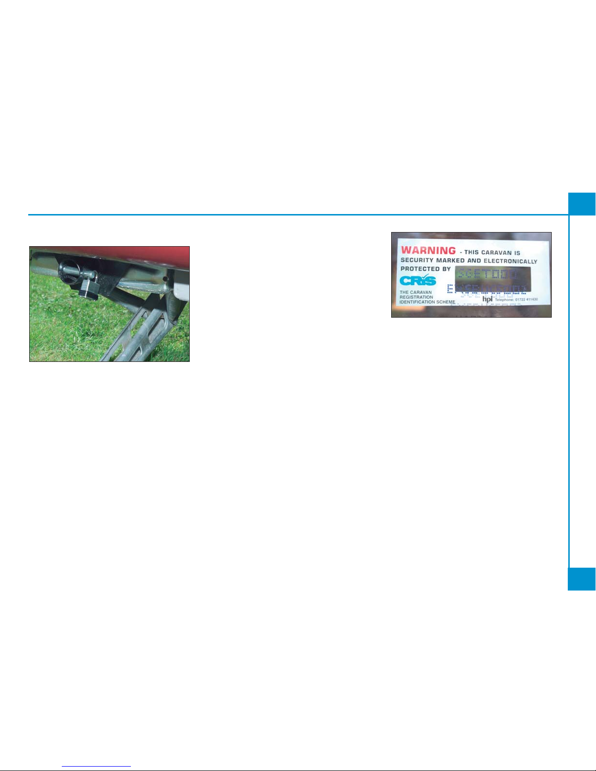
ANTI-WIND CORNER STEADIES
The rear corner steadies on all Explorer
touring caravans have a special cowling
that allows for the precise positioning of a
security bolt. Once the corner steadies
are down, the bolt is put in place and
padlocked. This prevents the potential
thief from being able to lift the corner
steadies making it extremely difficult to
tow the vehicle away. owners are advised
to purchase good quality, extended loop
padlocks in order to secure them.
CRIS - THE CARAVAN REGISTRATION
AND IDENTIFICATION SCHEME - VIN
CRiS is the national register of UK
manufactured touring caravans and was
established by the National Caravan
Council (NCC) in conjunction with HPI
Ltd.
All Explorer caravans are recorded on the
CRiS database by their unique 17 digit
Vehicle Identity Number (VIN). This VIN
and the caravan description are recorded
on the Touring Caravan Registration
Document, which is sent by CRiS to the
caravan's registered keeper.
Make a note of this number in the space
provided at the front of this guide and
make a separate note of the number to
keep safe at home.
CRiS issues Touring Caravan Registration
Documents which are the equivalent of
the log books issued by the DVLA for cars
- the Touring Caravan Registration
Document confirms the name of the
registered keeper, the VIN and full vehicle
description.
Shortly after purchasing this caravan you
should receive your Touring Caravan
Registration Document. It will be sent by
post to your home address.
WINDOW ETCHING & CHASSIS
MARKING
The VIN number is stamped onto the
chassis of the touring caravan and etched
onto all of the windows acting as a further
deterrent.
Your Touring Caravan Registration
Document will include a 17 character VIN
(Vehicle Identification Number), shown in
the top right -hand corner. This 17
character VIN will be die- stamped into the
caravan drawbar and chemically etched
on up to a maximum of 10 eye level
windows.
To protect yourself and your touring
caravan, never leave the Registration
Document in the caravan. For security
reasons keep it in a safe place.
If you sell the caravan please follow the
instructions on the Touring Caravan
Registration Document.
 Loading...