

Page 1

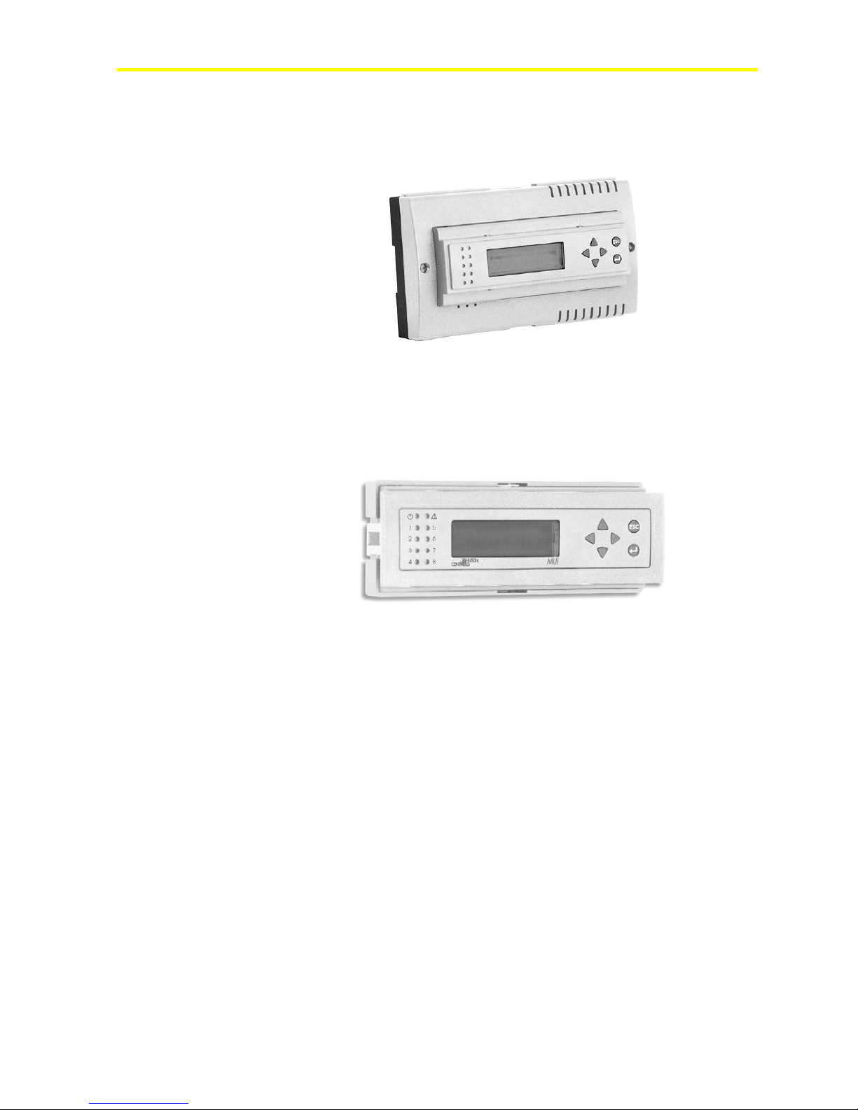
Technical Bulletin FX15 Controller
Issue Date November 14, 2005
FX15 Controller
Introduction to FX15...............................................................................3
Key Concepts....................................................................................................... 4
FX15 ...................................................................................................................................4
Installation...............................................................................................5
North American Emissions Compliance..............................................................................6
Detailed Procedures ...........................................................................................7
Mounting Instructions........................................................................................................ 7
Assembling the Integrated MUI......................................................................................... 8
Connection Details.......................................................................................................... 10
Connection Details for I/O Expansion (XT-XP Modules) on Local Extension Bus..........13
Connection Details for the N2 Open Card ...................................................................... 14
Connection Details for the LON Card ............................................................................. 17
Connection Details for the Remote User Interface ......................................................... 19
Connection Details for the Programming Key................................................................. 22
Inputs and Outputs...............................................................................26
Inputs and Outputs...............................................................................26
Introduction.......................................................................................................26
Key Concepts....................................................................................................27
Detailed Procedures .........................................................................................28
Isolation Diagram............................................................................................................ 28
FX15 I/Os Powered at 24 VAC.........................................................................................29
Analog Inputs..................................................................................................................30
Digital Inputs................................................................................................................... 36
Analog Outputs............................................................................................................... 37
Digital Outputs ................................................................................................................ 39
Extension Modules ......................................................................................................... 42
Troubleshooting................................................................................................44
Reading 9999 or Invalid from the Analog Inputs............................................................. 44
© 2005 Johnson Controls, Inc. 1
Code Number LIT-12011107
www.johnsoncontrols.com
Page 2

FX15 Controller Technical Bulletin
2
Can Not Properly Read Current Sensors........................................................................ 44
Operation...............................................................................................45
Introduction.......................................................................................................45
Key Concepts....................................................................................................46
Software Programming and Application Configuration................................................... 46
Alarm and Event Management ....................................................................................... 46
Time Scheduling............................................................................................................. 46
User Interfaces ............................................................................................................... 46
Security...........................................................................................................................47
Supervisory Option ......................................................................................................... 47
Application Upload/Download......................................................................................... 47
User Interface ................................................................................................................. 48
Security...........................................................................................................................50
Specifications and Technical Data ...................................................... 51
Ordering Codes.................................................................................................51
Technical Specifications..................................................................................54
I/O Technical Details....................................................................................................... 54
N2 Open Card................................................................................................................. 56
LON Connection ............................................................................................................. 56
Programming Key........................................................................................................... 57
FX15 ............................................................................................................................... 57
FX15 Extended Range ................................................................................................... 58
Page 3
FX15 Controller Technical Bulletin
Introduction to FX15
3
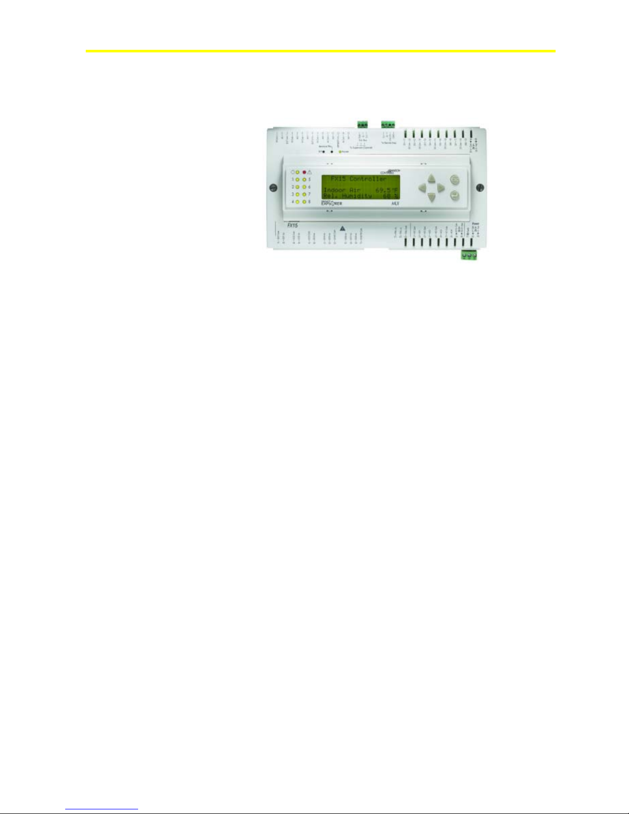
Figure 1: FX15 Classic
The FX15 is a high performance field controller of the Facility Explorer
system, specifically designed for commercial Heating, Ventilating, Air
Conditioning, and Refrigeration (HVACR) applications such as chillers
and rooftops, indoor packaged air conditioning units, air handling units,
and close control units.
The controller has 27 physical inputs and outputs and supports a wide
range of temperature sensors and actuating devices. Additional physical
inputs and outputs may be achieved by adding the XT/XP expansion
modules on the local Extension bus.
The FX15 controller is fully programmable or configurable, using the
FX Tools Pro software package, for a wide range of commercial
environmental control applications.
The FX15 controller is also available with a serial communication card
for integration into a Building Automation System with a LONWORKS®
or N2 Open bus network.
For stand-alone applications an on-board, real-time clock circuit is also
included to support the start-stop scheduling of equipment and real-time
based control sequences.
The FX15 can be integrated, as a slave device, in a distributed control
application managed by a master controller (FX16 Master Controller or
Master Display).
Optional accessories make the FX15 controller the state of the art
solution for the HVACR market:
• N2 Open, plug-in communication card
• LON, plug-in communication card
• user interface: Medium User Interface (MUI) and Large User
Interface (LUI)
Page 4

FX15 Controller Technical Bulletin
4
Key Concepts
FX15
Features
• fully programmable using FX Tools package
• interchangeable RS-485 - N2 Open or LON FTT10 communication
cards for supervisory system
• DIN rail mounting
• female connector option: screw or spring clamp connectors
• Input/Output (I/O) expansion modules
• optional user interfaces: integrated, local, or remote
• events displayed on user interface (up to 12 events)
• easy commissioning via proprietary commissioning tool
• Programming Key for easy application uploading and downloading
Page 5

FX15 Controller Technical Bulletin
Installation
This chapter takes you through the process of installing an FX15.
5
75 (2.95)
179 (7.05 )
44 (1.73)
215 (8.46)
122 (4.8)
142 (5.59)
BB
Figure 2: Mounting Dimensions for FX15 (Shown with Integral User
Interface and Screw Connectors)
180.5 (7.11)
66 (2.6)
49 (1.93)
35 (1.38)
46.5 (1.83)
Panel cut-out
Figure 3: Panel Cut-Out Dimensions for User Interfaces
Two different types of terminal connectors are available: spring clamp
or screw connectors. The screw connectors are included, while the
spring clamp connectors must be ordered separately. For details, see
Ordering Codes.
IMPORTANT: For installation with Clas s 2 inputs and outputs only, no
special mounting precautions are generally necessary. For use with one or
more line voltage outputs (above 30 V), installation as part of a UL 508A
industrial control panel may be required by the local building or electrical
authority. These controllers are presently UL Recognized as Temperature
Indicating and Regulating Equipment in accordance with UL 873. UL Listing as
Open Energy Management Equipment per UL 916 is pending.
Page 6

FX15 Controller Technical Bulletin
6
North American Emissions Compliance
United States
This equipment has been tested and found to comply with the limits for
a Class A digital device pursuant to Part 15 of the FCC Rules. These
limits are designed to provide reasonable protection against harmful
interference when this equipment is operated in a commercial
environment. This equipment generates, uses, and can radiate radio
frequency energy, and if not installed and used in accordance with the
instruction manual, may cause harmful interference to radio
communications. Operation of this equipment in a residential area is
likely to cause harmful interference, in which case the user will be
required to correct the interference at his/her own expense.
Canada
This Class (A) digital apparatus meets all the requirements of the
Canadian Interference-Causing Equipment Regulations.
Cet appareil numérique de la Classe (A) respecte toutes les exigences du
Règlement sur le matériel brouilleur du Canada.
Page 7

FX15 Controller Technical Bulletin
Detailed Procedures
Follow these instructions to properly install and connect the FX15.
!
WARNING: Risk of Electric Shock. Disconnect power supply before
making electrical connections. Contact with components carrying hazardous
voltage can cause electric shock and may result in injury or death.
Mounting Instructions
To mount an FX15:
1. Snap the controller onto the 35 mm (1.38 in.) rail for DIN rail
mounting. To release the controller, insert a screwdriver in Slots B
and lift the retaining clip. Since the retaining clip is spring-loaded,
you can also remove the controller without a screwdriver by
carefully pushing the controller up against the clip and then tilting
the top forward to release the top lug from the DIN rail.
2. Make wiring terminations with detachable connectors, which accept
1 x 1.5 mm2 (0.002 in.2)/14 AWG cable. There are two types
available: screw and cage clamp connectors. For details, see
Ordering Codes.
7
Terminations of the Supervisor Link, Expansion Bus, and Remote
Display are made via the connectors provided with the controller.
3. Verify that the wiring has been correctly installed and that voltage
levels are appropriate for the various input signals according to the
application.
4. Set the jumpers and address switches of the controller as required.
For more information, see Jumper Details.
Page 8
FX15 Controller Technical Bulletin
8
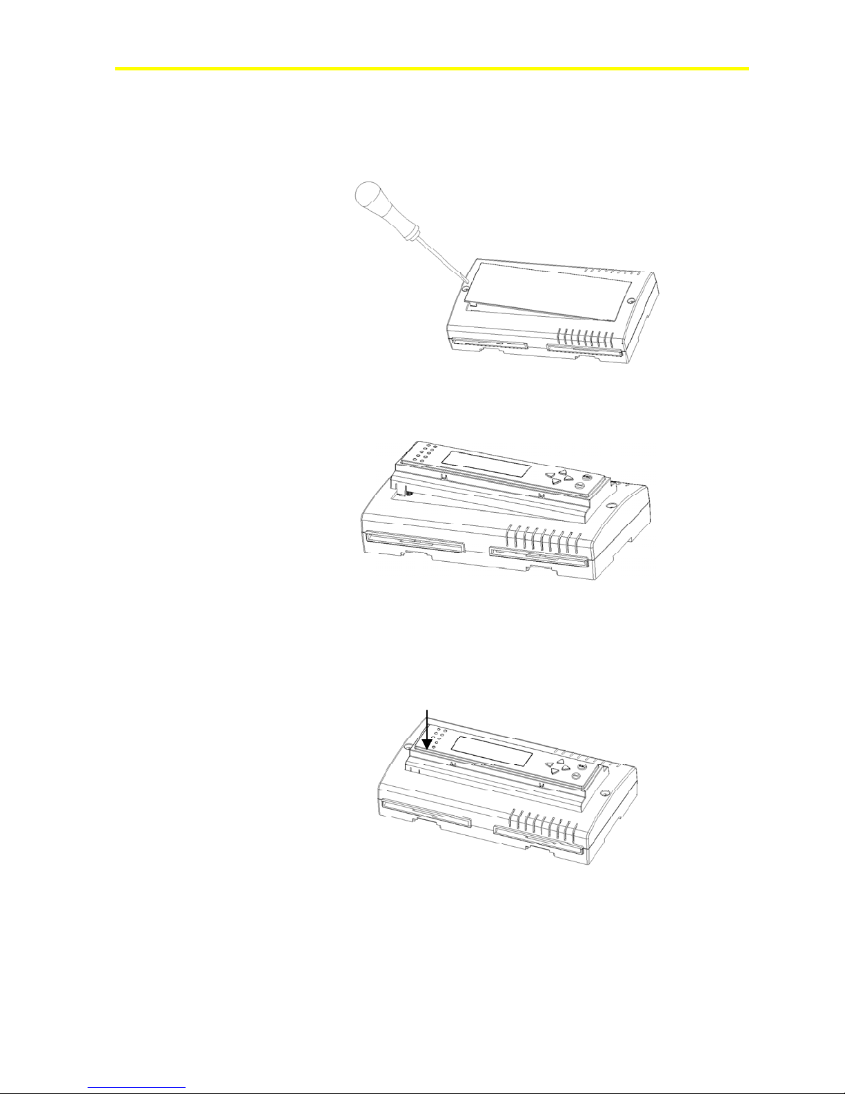
Assembling the Integrated MUI
To assemble the integrated MUI:
1. Remove the controller front cover.
2. Hook the display to the top FX15 cover.
Figure 4: Open the Controller
Figure 5: Display Installation
3. Push down until it locks.
PUSH
Figure 6: Display Locking
Page 9
FX15 Controller Technical Bulletin
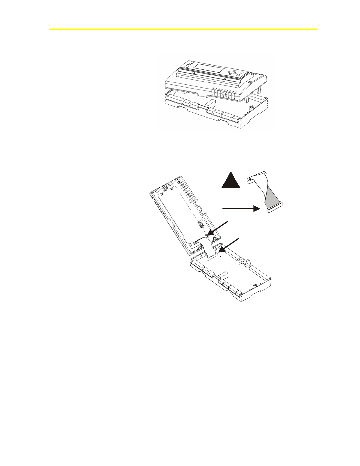
4. Open the controller.
Figure 7: Open the Controller
5. Insert the flat in the specific holes.
!
9
NO
Figure 8 : Flat Cable Inserting
6. Close the controller and secure it with the two screws.
Page 10
FX15 Controller Technical Bulletin
10
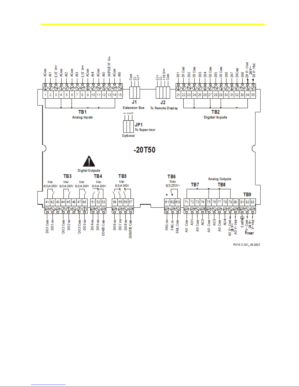
Connection Details
LP-FX15D2x and LP-FX15D7x Wiring Diagram
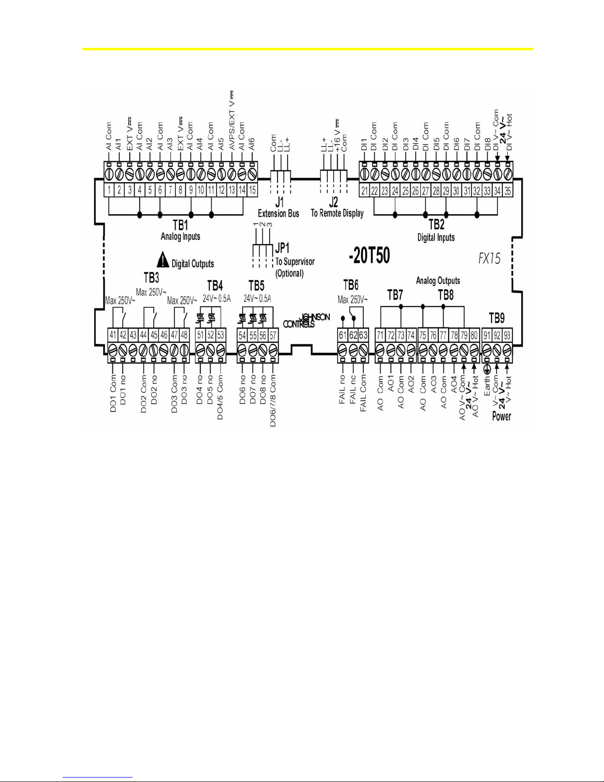
Figure 9: Connection Details for the FX15 (9 Relays)
Page 11
FX15 Controller Technical Bulletin
LP-FX15D1x and LP-FX15D6x Wiring Diagram
11
Figure 10: Connection Details for the FX15 (5 Triacs+4 Relays)
Consider the following information when you work with the
connections details for the FX15:
• All commons are electrically dependent.
• Analog outputs are opto-isolated and are externally powered at 24
VAC. In order to maintain the opto-isolation, a separate power
supply (3 VA) must be used only for the analog outputs.
• Digital inputs are opto-isolated and are externally powered at 24
VAC. In order to maintain the opto-isolation, a separate power
supply (3 VA) must be used only for the digital inputs.
Page 12
FX15 Controller Technical Bulletin
a
b
d
e
12
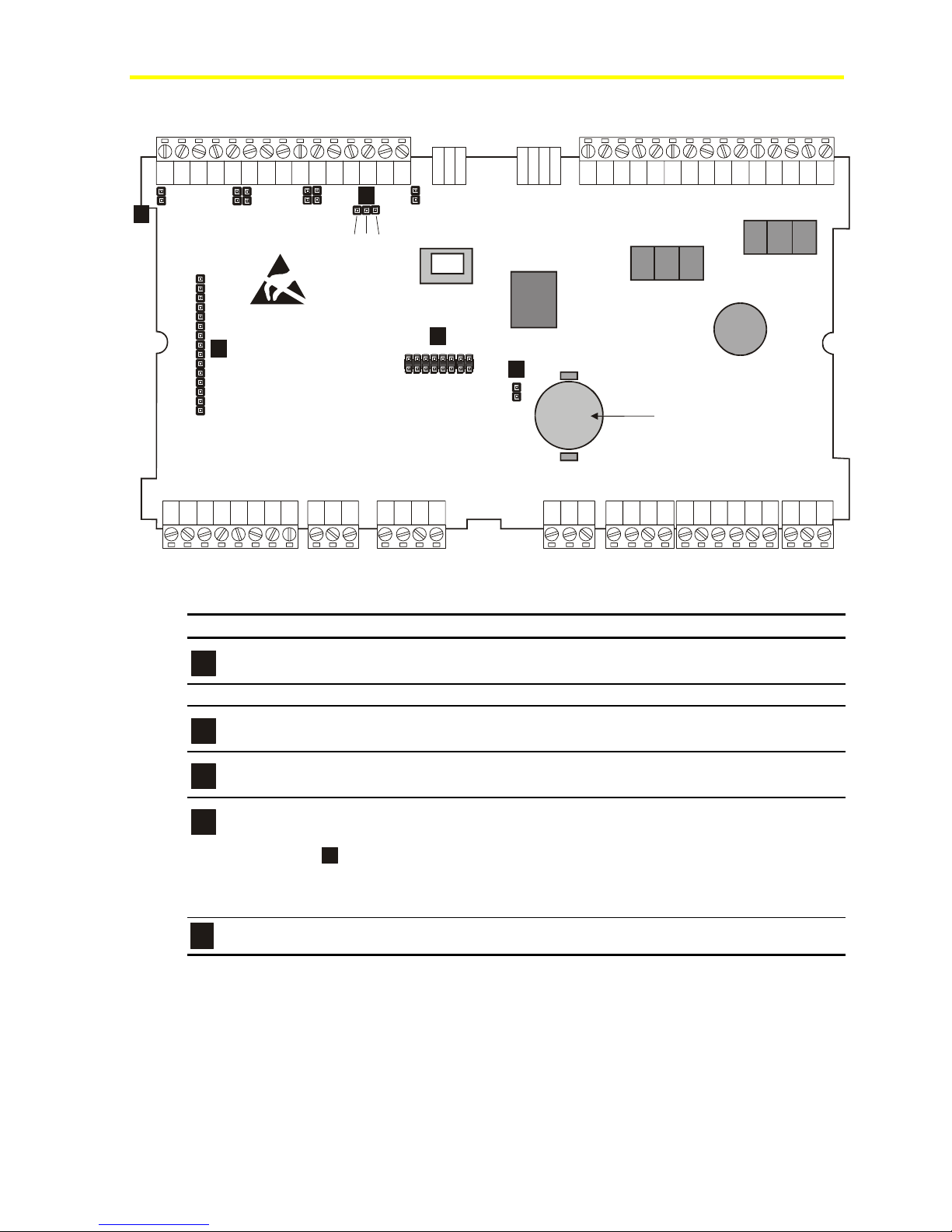
Jumper Details
b
a
AI1 AI2
AI3
AI4 AI5
AI6
1 2 3
e
Figure 11: Jumper Connections
Table 1: Jumper Connections
c
Analog Input (AI) 0-20/4-20 mA Resistive, 0-10 V or Ratiometric
AI1-AI6 Jumpers Closed Jumpers Open
Sensors Power Supply AVPS +5 V EXT VDC+16 V
Terminal Number 13 Pins closed between 1
Battery Type CR2032, average life time: 3 years, dispose OFF
Pin strip closed: battery backup enabled
Pin strip open: battery excluded (to preserve charge)
Jumper
be kept in storage without power for an extended period of time. The jumper must be set to
ON before the controllers is installed and powered up; otherwise back-up RAM and RTC will
not be enabled.
Plug-in connector for optional cards insertion
is set to ON at the factory and should only be set to OFF if the controllers are to
d
d
and 2
c
Battery
(Default configuration)
Pins closed between 2 and 3
(Default configuration)
Page 13
FX15 Controller Technical Bulletin
Connection Details for I/O Expansion (XT-XP Modules) on Local
Extension Bus
13
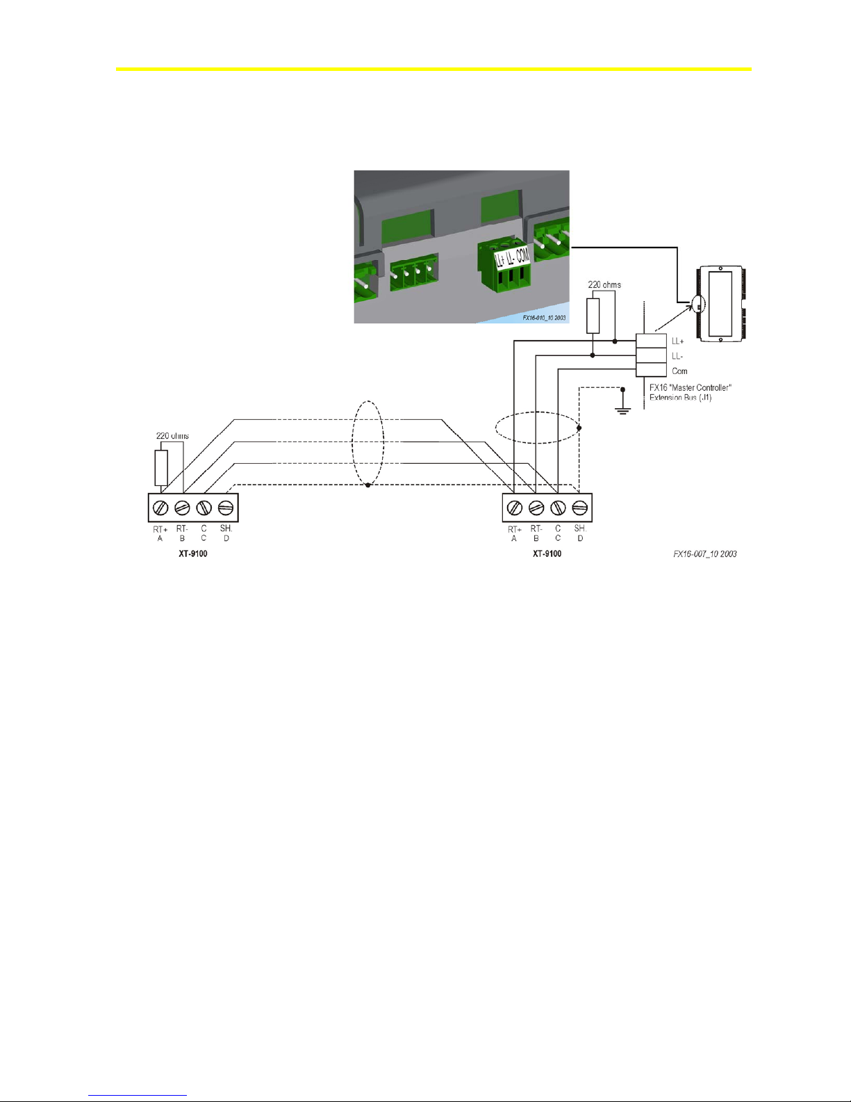
Figure 12: Connection Details for the XT/XP Modules
Consider the following information when you work with the
connections details for the XT/XP Modules:
• maximum XT modules: 4 XT91D00s
• maximum bus length: 1.2 m (4.0 ft)
• Install a repeater (for example, RP-9100-810x) to regenerate the
RS-485 signal in case more than 31 N2 devices have to be
connected on the same N2 bus trunk and/or the N2 bus trunk length
is more than 1,200 m (4,000 ft).
• Install 220 ohm end-of-line resistors at each end of the XT-Bus line
when the bus length is greater than 100 m (330 ft). When the bus
length is less than 100 m (330 ft), insert only one 220 ohm resistor
at the FX15 end only.
Page 14
FX15 Controller Technical Bulletin
Selectio
14
Connection Details for the N2 Open Card
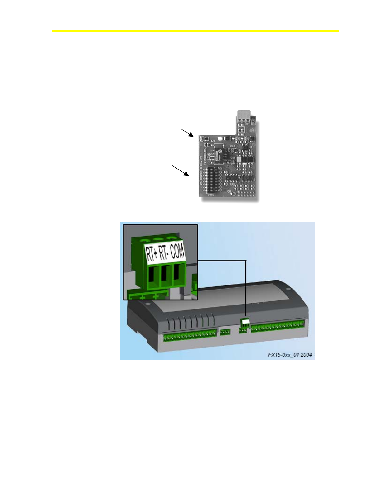
The FX15 comes either with the N2 Open Card preassembled or the
card can be assembled at a later time in the field. For details, see
Ordering Codes.
The N2 Open plug-in serial card allows the FX15 to be connected to an
N2 Open serial network through the RS-485 standard.
LED
Address
n
Figure 13: N2 Open Plug-in Communication Card
Figure 14: N2 Open Card Connection
Assembling the N2 Communication Card
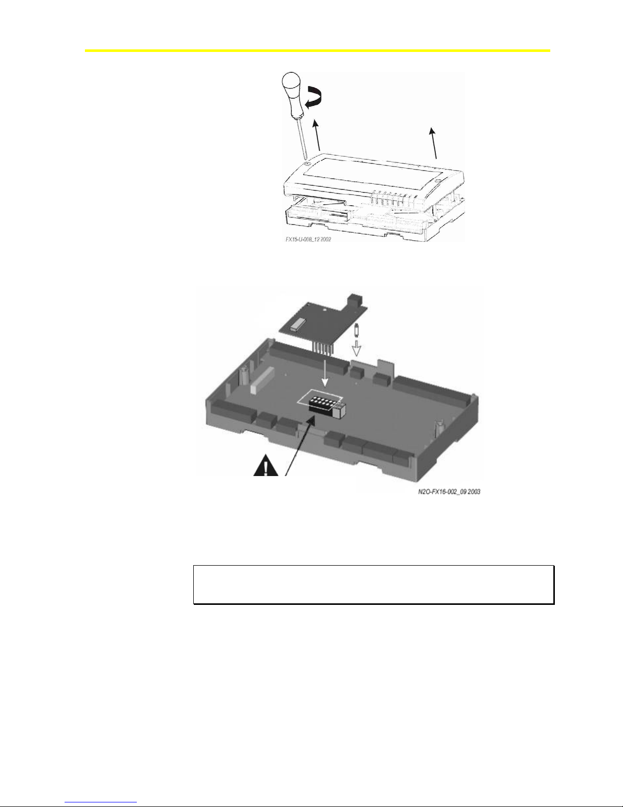
To assemble the N2 communication card:
1. Power off the controller (hot plug-in not allowed).
2. Open the controller. See Figure 15.
Page 15
FX15 Controller Technical Bulletin
Figure 15: Open the Controller
3. Insert the card. See Figure 16.
15
Align the pins as shown in figure.
Figure 16: Insertion of the N2 Open Card
4. Set the address dip-switches.
5. Replace the lid and close it.
IMPORTANT: The Complementary Metal Oxide Semiconductor (CMOS)
integrated circuit in the controller and on the communication card are sensitive
to static current discharges. Take suitable precautions.
Page 16

FX15 Controller Technical Bulletin
16
Address Selection
Through the dip-switches (see Figure 13), select the serial address of the
controller in the N2 Open network. The address selection is done in
binary mode.
Example.:• 1st ON, all others open
address = 20 + 01 + … = 1
• 1st ON, 4th ON, all others open
address = 20 + 01 + 02 + 23 = 9
The address zero is not allowed. The factory default address
configuration is 1.
IMPORTANT: Cycle the controller power in order for new serial address to
become active.
Network Layout
Refer to the N2 Communication Bus Technical Bulletin (LIT-636018).
Page 17
FX15 Controller Technical Bulletin
Connection Details for the LON Card
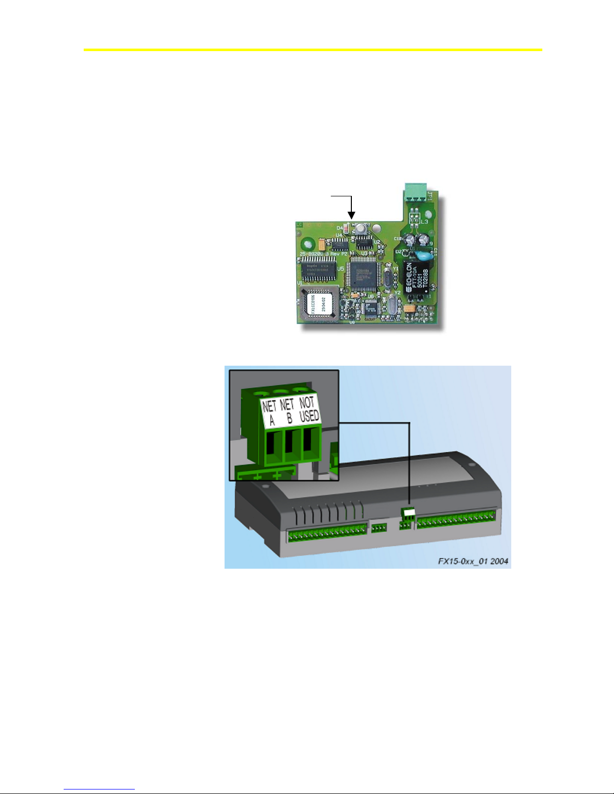
The FX15 comes either with the LON card preassembled or
communication-less and the card can be optionally assembled later in
the field. For details, see Ordering Codes.
The LON plug-in serial card allows the FX15 to be connected to a
ONWORKS network.
L
Service PIN
Reachable from the
controller top lid
17
Figure 17: LON Plug-in Communication Card
Figure 18: LON Card Connection
Assembling the LON Communication Card
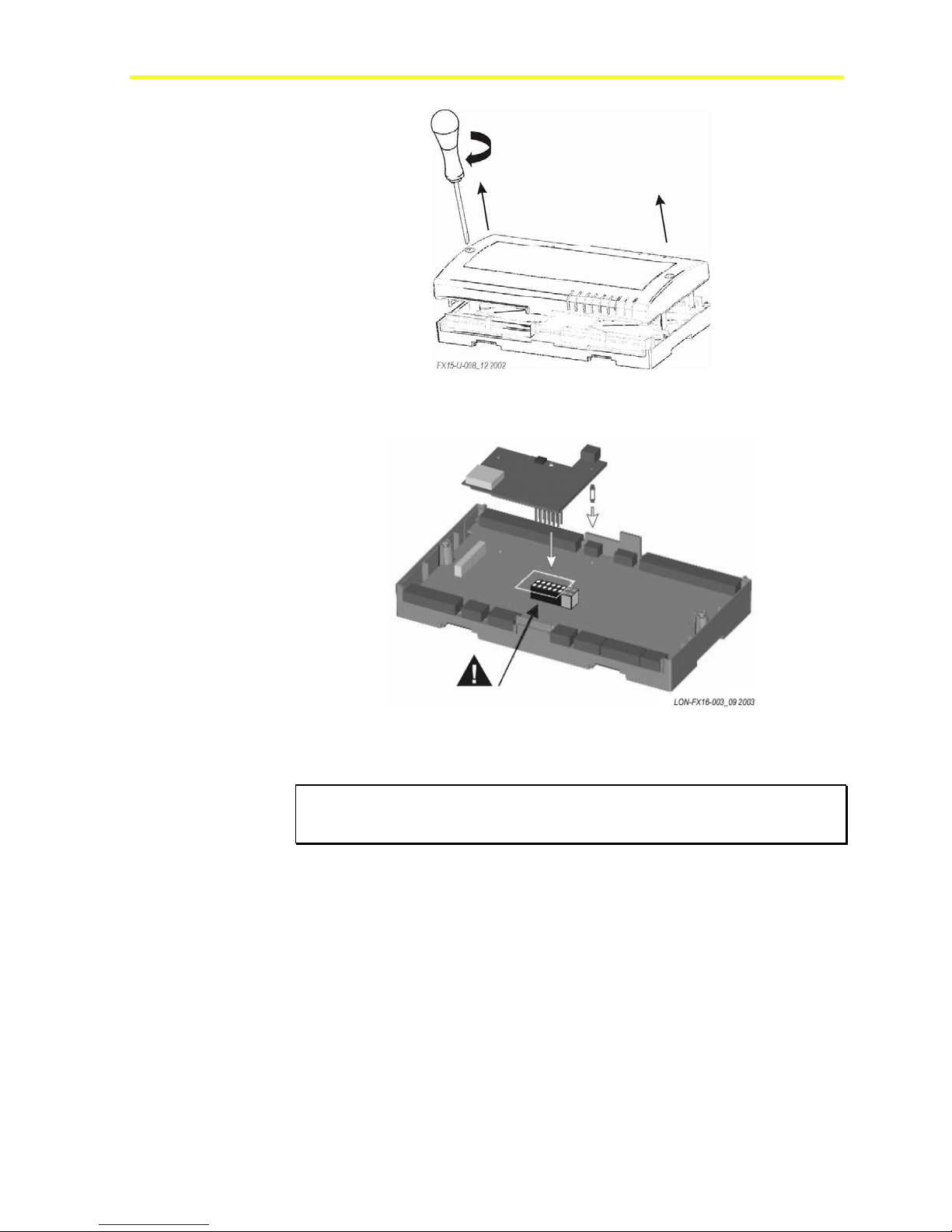
To assemble the LON communications card:
1. Power off the controller (hot plug-in not allowed).
2. Open the controller. See
Figure 19.
Page 18
FX15 Controller Technical Bulletin
18
3. Insert the card. See Figure 20.
Figure 19: Open the Controller
Align the pins as shown in figure.
Figure 20: Insertion of the LON Card
4. Replace the lid and close it.
IMPORTANT: The CMOS integrated circuit in the controller and on the
communication card are sensitive to static current discharges.
Take suitable precautions.
Refer to the LONWORKS FTT-10A Free Topology User’s Guide
(078-0156-01F) for technical guidelines associated with free topology
restrictions. Refer to the Junction Box and Wiring Guidelines for
Twisted Pair LONWORKS Networks (005-0023-01) for more detailed
information on wiring specification. These documents are available on
the Echelon® Web site (www.echelon.com).
Page 19
FX15 Controller Technical Bulletin
Connection Details for the Remote User Interface
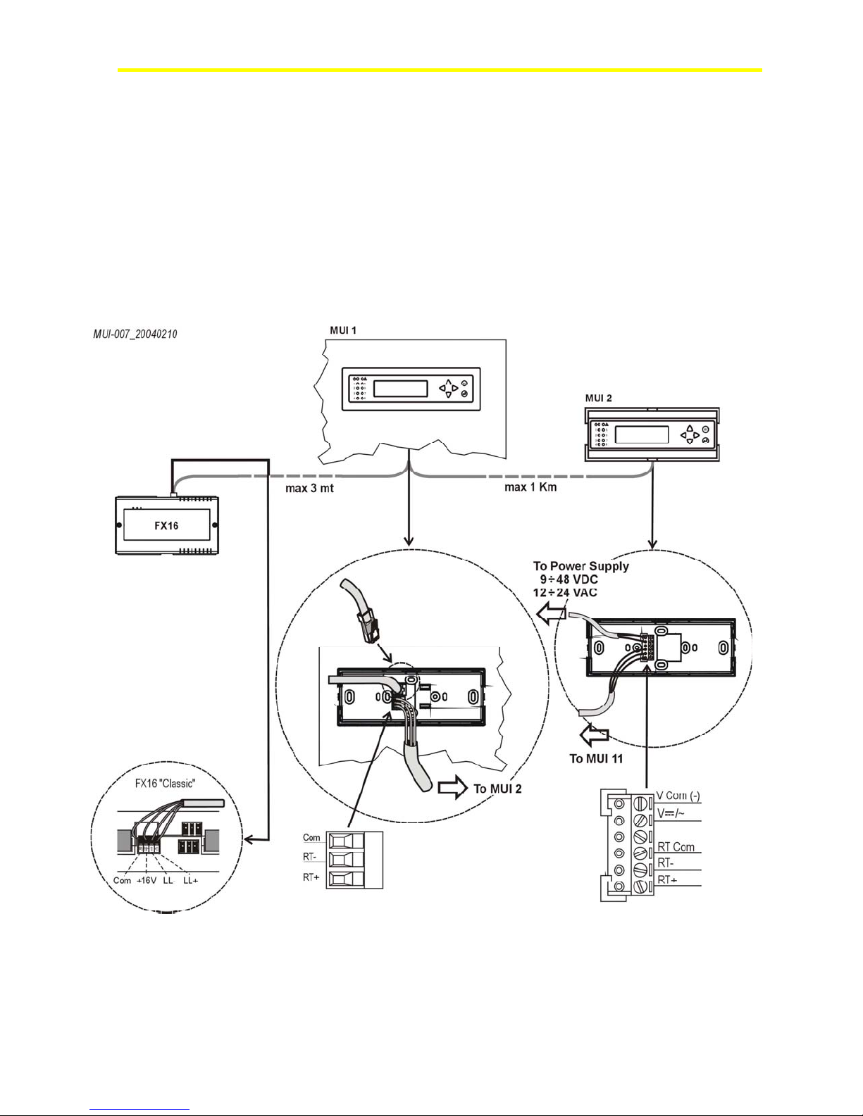
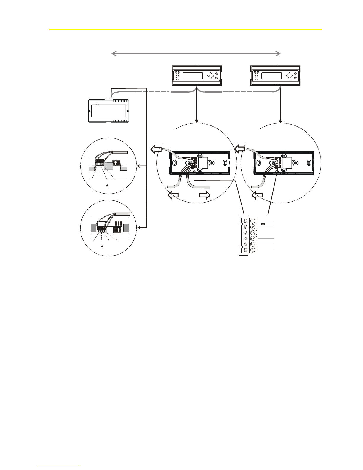
The FX15 can support up to two Medium User Interfaces (MUIs) at the
same time.
The MUI is available in 2 models: panel mount (up to 3 m [9.8 ft]) and
wall mount (up to 1 km [0.6 mi]). The FX15 can support 1 panel mount
MUI plus 1 wall mount MUI or 2 wall mount MUIs (see
Figure 22).
For the panel mount connection use the pre-cabled connection kit
(LP-KIT007-000C), 3 m (9.8 ft) long, with a phone jack on the MUI
side and a preassembled screw connector on the FX15 side.
19
Figure 21 and
Figure 21: Installation for One Local and One Remote MUI
Page 20
FX15 Controller Technical Bulletin
20
MUI-008_10 2002
FX15
Max 1 Km, total length
MUI 2MUI 1
1
1
5
2
6
3
7
4
8
5
2
6
3
7
4
8
FX15 "Universal"
LL+ LL- +9V Com
FX15 "Classic"
Com +16V LL- LL+
To Power Supply
9 ÷ 48 VDC
12 ÷ 24 VAC
(not used)
To FX15
To MUI 2
V Com (-)
V /~
RT Com
RT-
(not used)
RT+
Figure 22: Installation for Two Wall Mount MUIs
To Power Supply
9 ÷ 48 VDC
12 ÷ 24 VAC
To MUI 1
(+)
Page 21
FX15 Controller Technical Bulletin
Assigning the Medium User Interface’s N2 Address in Case
of Multiple Connections
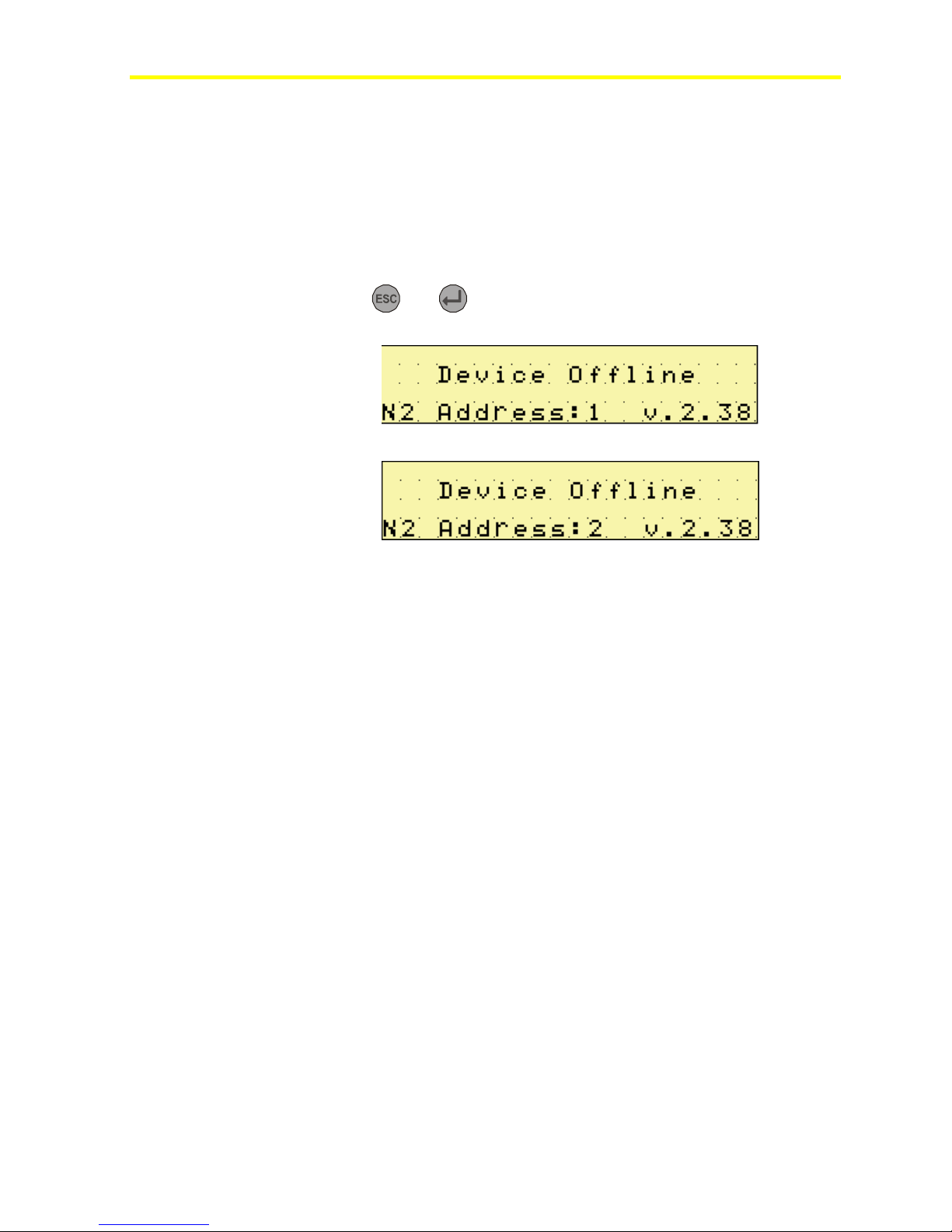
At power up, the MUI automatically has a default N2 address equal
to 1.
If you connect multiple MUIs, the second MUI N2 Address must be
changed to avoid communication conflicts.
When the second MUI displays Device Offline, as shown in Figure 23,
press the
and
keys simultaneously to switch the N2 Address
to 2. See Figure 24.
Figure 23: MUI N2 Address Selection
21
Figure 24: MUI N2 Address Changed
Page 22
FX15 Controller Technical Bulletin
2
22
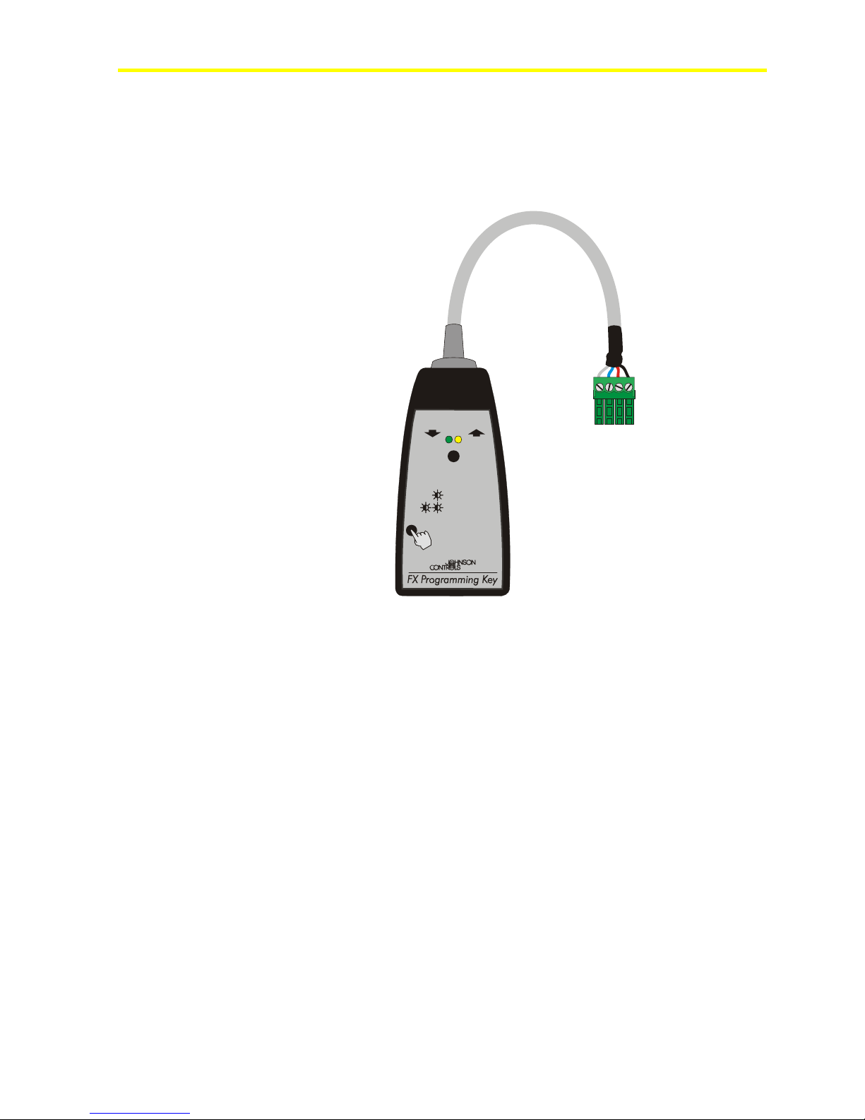
Connection Details for the Programming Key
The Programming Key is used to upload an application from a personal
computer or from a preprogrammed FX15. The application is then
downloaded to other FX15 controllers.
Upload Download
Download / Upload
LED
LEDs
Download / Upload failed
<1 sec
to select
>3 sec
to confirm
>15 sec
for MEMORY ERASE
Figure 25: Programming Key
LP-KIT100-001_09 200
Page 23
FX15 Controller Technical Bulletin
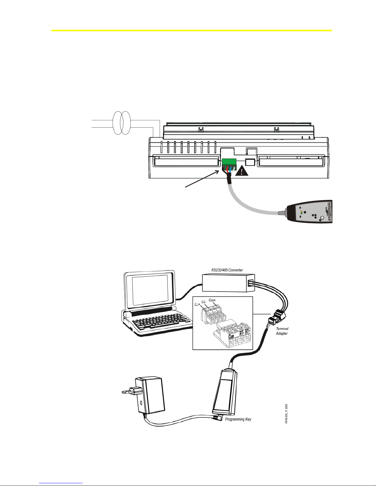
Connecting the Programming Key to an FX15
To connect the Programming Key to an FX15:
1. Power off the controller.
2. Detached any connect user interfaces from the Remote Display Port
JP2.
3. Plug the Programming Key into the Display Port (see Figure 26).
24 VAC230 VAC
Remote Display Port
(JP2)
FX16-018_09 2003
Figure 26: Programming Key Connection to FX15
23
E
d
S
e
l
A
i
R
a
f
d
a
o
l
n
w
o
D
d
a
o
l
p
U
E
d
d
Y
a
a
o
R
o
l
l
p
O
p
m
t
r
U
M
i
U
c
f
/
/
E
e
n
l
d
d
M
o
e
a
c
a
s
r
o
l
o
o
o
l
o
f
n
t
t
n
w
c
w
o
e
o
c
c
s
D
e
e
D
s
s
5
1
3
1
>
>
<
D
E
L
s
D
E
L
4. Power the controller and download/upload the application.
Connecting the Programming Key to a Personal Commuter
Figure 27: Programming Key Connection to PC
Page 24

FX15 Controller Technical Bulletin
24
To connect the Programming Key to a personal computer:
1. Connect the terminal adapter (included in the programming key kit)
to the RS-232/485 converter connected to the personal computer.
Table 2: Terminal Adapters
Adapter RS-232/485 Converter
1
2
3
4
Com
Not used
RTRT+
2. Power the key via AC/DC adapter.
3. Launch FX Loader.
4. Upload the application.
Performing a Programming Key Memory Erase
If the key is already loaded with an application and there is the necessity
to substitute it with a different application, the user has to do a memory
erase.
The memory erase is automatically performed by FX Loader. However,
in the case where the application is loaded from a personal computer or
where the application has to be loaded from another FX15, the user has
to manually perform the memory erase.
To perform a Programming Key memory erase:
1. Power up the key, either by hot-plugging it to an FX15 (already on)
or with an AC/DC adapter.
2. Initiate the memory erase by pressing the Programming Key button
for 15 seconds.
During the erase, the green Light-Emitting Diode (LED) slowly
blinks. Then the green and the yellow LED blinks, 2 times
alternatively, and finally the green LED remains steady on. The
flash erases.
If the two LEDs blink simultaneously, it means that the erase process
has failed. Retry. When the memory is completely erased, the LEDs
stop blinking. The key is now ready for a new upload. The memory
erase is also necessary if the previous upload from the FX15 goes
wrong (communication has been interrupted).
Page 25

FX15 Controller Technical Bulletin
Error Codes
The error codes can only be seen if the FX15 has been mounted with an
integrated MUI display (LP-DIS60U10-C).
Table 3: Error Codes
Error
Code
51
52
52
Meaning Possible Cause Action
Private ID
mismatch
Memory full Attempt to upload an
Memory empty Attempt to download an
Controller and
application in the key
have different protection
IDs
application to a key
already loaded
application from an
empty key
Save the application with
the proper ID (if available)
and retry the download.
Proceed with the memory
erase and retry uploading.
Upload the key with the
target application.
25
Page 26
FX15 Controller Technical Bulletin
26
Inputs and Outputs
Introduction
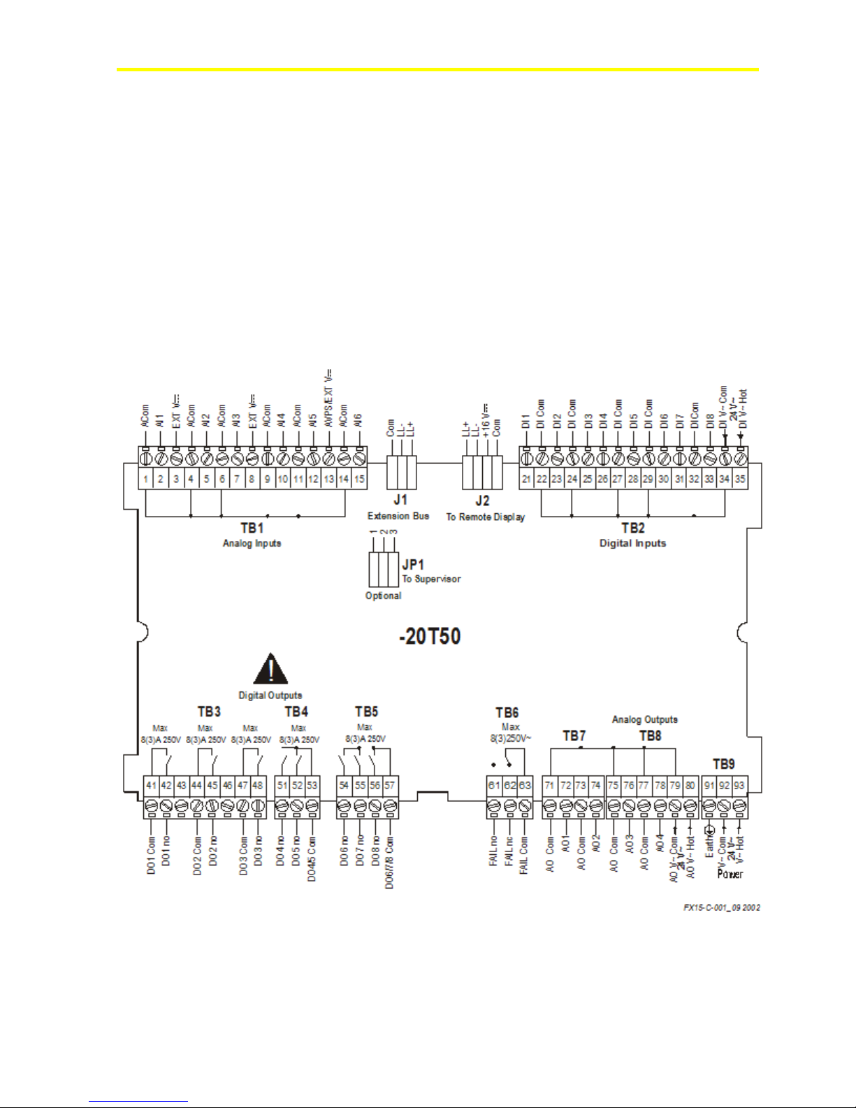
The FX15 features the following I/O Channels:
• six high resolution Analog Inputs (13 bit, A/D Converter)
• eight opto-isolated Digital Inputs from potential free contacts, each
with transition counter
• nine Digital Outputs (4 Relays and 5 optionally Relays or triacs)
• four opto-isolated Analog Outputs
Figure 28: FX15 I/Os
Page 27

FX15 Controller Technical Bulletin
Key Concepts
Analog Inputs
The FX15 accepts six high resolution, universal analog inputs; each of
them can be configured as active or passive by application software and
jumper configurations.
Digital Inputs
The FX15 accepts eight opt-isolated digital inputs from voltage free
contacts.
Analog Outputs
The FX15 provides up to four 0-10 VDC opto-isolated analog outputs.
Digital Outputs
The FX15 provides nine digital outputs, available in two hardware
configurations with 9 Relays or 4 Relays and 5 triacs.
27
Page 28
FX15 Controller Technical Bulletin
28
Detailed Procedures
Isolation Diagram
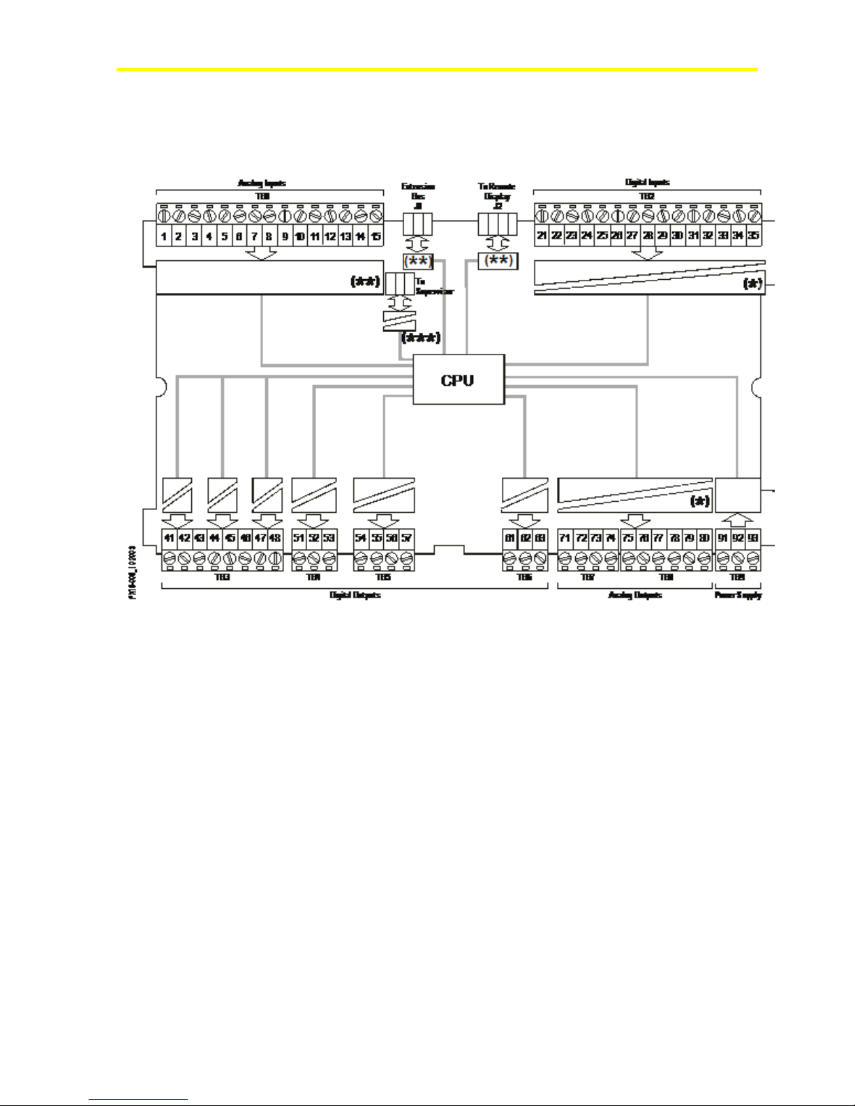
Figure 29: Insulation Diagram
(*) Opto-isolated (maximum 500 V) if an additional separated power
supply is used
(**) Not isolated
(***) DC/DC converted with dielectric strength up to 1000 V
Page 29
FX15 Controller Technical Bulletin
A
FX15 I/Os powered at 24 VAC
29
15 V
Figure 30: Powering FX15 I/Os
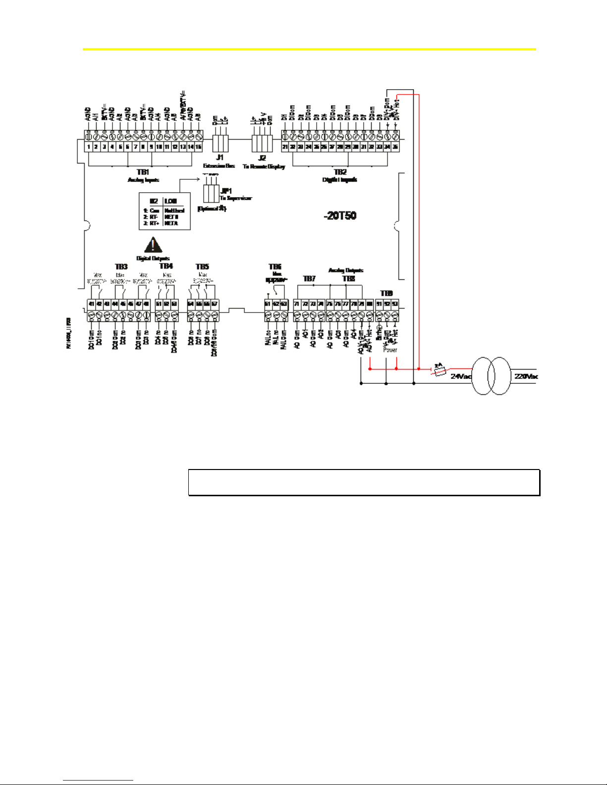
In order to maintain the insulation between the FX15 power supply and
the I/Os, run the power supply cable respecting the polarity as shown in
Figure 30, adding an External Protection fuse (2 A) to avoid mis-wiring.
IMPORTANT: Not respecting the power supply polarity will result in a short
circuit causing the blowing of the external fuse.
Page 30
FX15 Controller Technical Bulletin
AI4AI5A
30
Analog Inputs
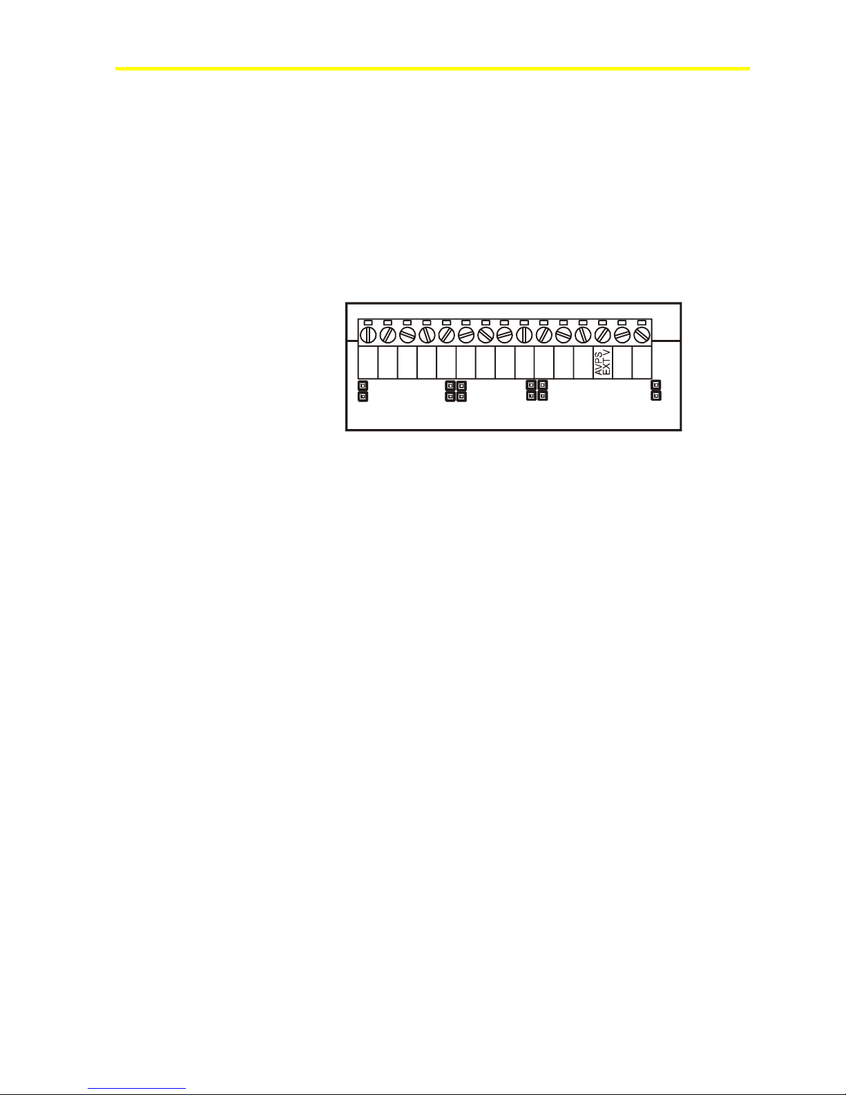
The six high-resolution analog inputs can be configured to accept a
wide range of voltage, current and resistive input signals.
See I/O Technical Details for the complete FX15 I/O table.
A dedicated jumper is placed on board for each analog input. This
jumper should be installed in its closed position if the connected sensor
provides a current signal (0-20/4-20 mA). This jumper should be
installed in its open position if the connected sensor provides a resistive,
ratiometric, or voltage (0-2/0-10 V) input signal.
AGND
AI1 AI2
a
FX16-025_1 0 2003
AI1
Figure 31: Analog Input Jumpers
AI2
AGND
EXT V
AI3
AGND
AI3
AI4
AGND
EXT V
AI5
AGND
AI6
AGND
I6
The active sensor (voltage or current) inputs are ranged using
programmable range parameters within the application software. These
parameters, HighRange and LowRange, define the equivalent values for
reading at High (10 V, 20 mA) and Low (0 V, 4 mA, 0 mA) signal
input. Voltage and current inputs from differential pressure transducers
can be linearized by a square root function (SQRT), which operates
over the complete range of the input.
The passive sensors (resistance) have a preprogrammed linearization
curves within the application software. For these sensors, the
measurement range is fixed. The user can set the reliability range via
software.
The read signal is converted by the FX15 according to the related
Analog Input object setup, available setup are:
• Linear 0-10 V
• SQRT 0-10 V
• Linear 0-10 V, 20% suppression (2-10 V)
• Linear 0-2 V
• SQRT 0-2 V
• Linear 0-2 V, 20% suppression (0.4-2 V)
• Linear 0-20 mA
• SQRT 0-20 mA
• Linear 0-20 mA, 20% suppression (0.4-2 mA)
• Resistance 2k ohm
Page 31

FX15 Controller Technical Bulletin
• A99
• NTC 2k2 ohm
• Ni1000 JC
• Ni1000 JC Extended
• Ni1000 Landis and Gyr
• Ni1000 DIN
• Pt1000
• Ratiometric
The measurement unit is also configurable to enable the controller to
propagate via network the measured value according to the appropriate
scale unit. Available configurable units are:
• Temperature
• Percentage
• Air Pressure
• Liquid Pressure
31
• Flow
• Concentration
• Ampere
• Voltage
A configurable filter constant in seconds is performed by the FX15 on
its Analog Inputs for the reduction of signal instability. An additional
Anti-Spike filter can be configured to limit the rate of change of the
input values to the value indicated by this attribute.
The FX15 provides a jumper configurable (Terminal 13) +5V AVPS
(Analog Voltage Power Supply) or a +16V External VDC, supply for
active analog input sensors (See
Jumper Details at page 12)
The EXT VDC can supply up to 80 mA for a maximum of four 0/4-20
mA active sensors. The AVPS can supply up to 10 mA for ratiometric
sensors.
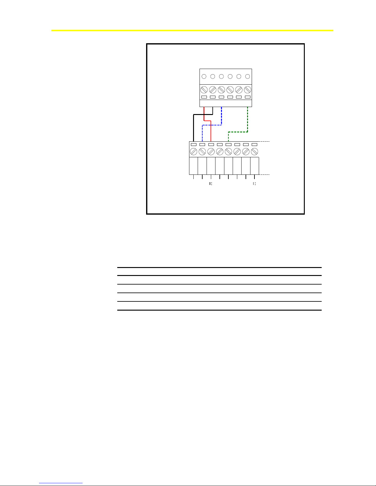
Connecting Active 0-10 V Sensors
The FX15 can accept all the active temperature, pressure, flow and
humidity sensors providing 0-10 VDC signals.
Figure 32 shows the connection between an FX15 and an HT-9001
probe.
Page 32
FX15 Controller Technical Bulletin
32
Active Humidity and Temperature Sensor
HT-9001-UDx
CAB -Bt
1 2 3
AI1
AGND
4 5
AGND
EXT V
FX15
FX16
-
AI2
6 7
AGND
8
AI3
EXT V
Figure 32: Active 0-10 V Probe, Connection Diagram
The inputs must be pre-configured in order to accept 0-10 V signals by
the application software resident in the FX15. The AI Jumpers must be
opened (factory default setting) in order to accept voltage inputs.
Table 4: Active 0-10 V Sensors
FX15 Terminals HT-9001 Terminals Description
AGND (1)
EXT V (3)
AI1 (2)
AI2 (5)
A Common Reference
C Sensor Power Supply 16 V, 80mA
B Humidity Output 0-10 V
Bt Temperature Output 0-10 V
Note: The numbers between the brackets are the FX15 terminal
numbers.
Page 33
FX15 Controller Technical Bulletin
Connecting Passive Resistive Sensors
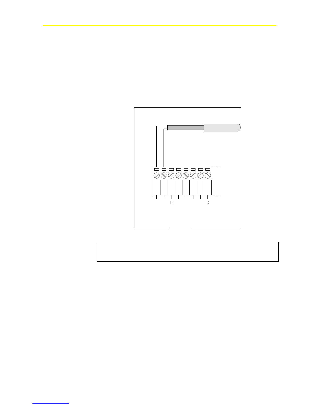
The FX15 analog inputs accept linear resistive signals as the Resistive
2kΩ. The Analog Input software can also linearize signals provided by
the most common sensors as Ni1000, A99, Pt1000, and NTC 2k2.
The inputs must be preconfigured in order to accept A99 resistive
signals by the application software resident in the FX15. The AI
Jumpers must be opened in order to accept resistance input (Factory
default setting). Figure 33 shows an A99 wiring diagram. The resistive
sensors have to be connected in the same way.
A99BB
Resistive Temperature Sensor
33
1 2 3
AGND
Figure 33: A99 Resistive Sensor Connection Diagram
IMPORTANT: The two resistive probe leads are the same, in that they have
no polarity; therefore, it is not necessary to respect any specific order when
connecting to the terminal block.
AI1
4 5
AGND
EXT V
FX16
FX15
AI2
6 7
AGND
8
AI3
EXT V
Page 34
FX15 Controller Technical Bulletin
34
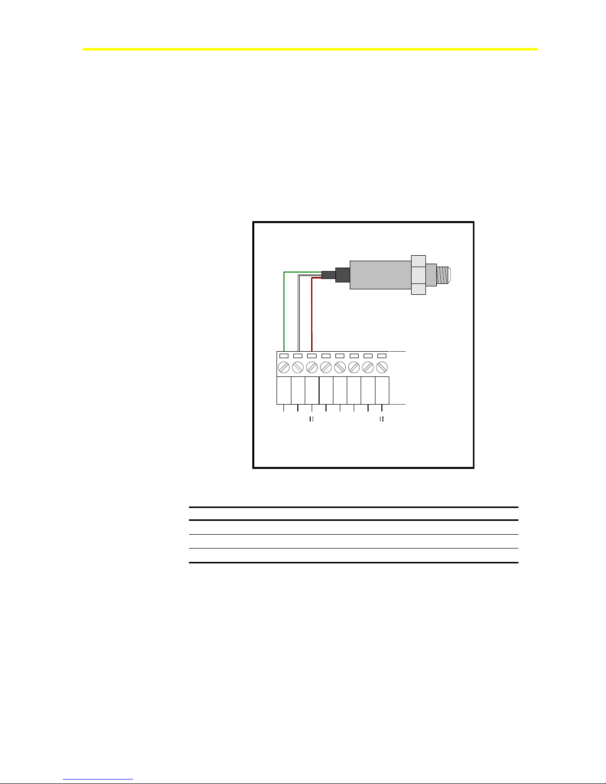
Connecting Active Current Sensors
The FX15 analog inputs can accept a maximum of four active current
sensors, powered by the FX15 itself, in the range 0-20 mA or 4-20 mA.
The AI has to be configured via software (and hardware jumpers) in
order to accept current signals. If a 4-20 mA sensor has to be connected,
the specific hardware jumpers has to be closed (see Figure 31) and the
application can be configured through the FX Builder, setting 0-20 mA,
20% suppression.
The FX15 can be connected to P299xAx series of Johnson Controls®
pressure sensors which generate a 4-20 mA signal.
P299xAx
Active Pressure Sensor
1 2 3
AGND
AI1
4 5
AGND
EXT V
AI2
6 7
AGND
8
AI3
EXT V
FX16
Figure 34: Pressure Sensor Connection Diagram
Table 5: Active Current Sensors
FX15 Terminals P299xAx Cable Description
AGND (1)
EXT V (3)
AI1 (2)
Green Common Reference
Brown Sensor Power Supply 16 V, 80 mA
White Pressure Output 4-20 mA
Note: The numbers between the brackets are the FX15 terminal
numbers.
Page 35
FX15 Controller Technical Bulletin
A
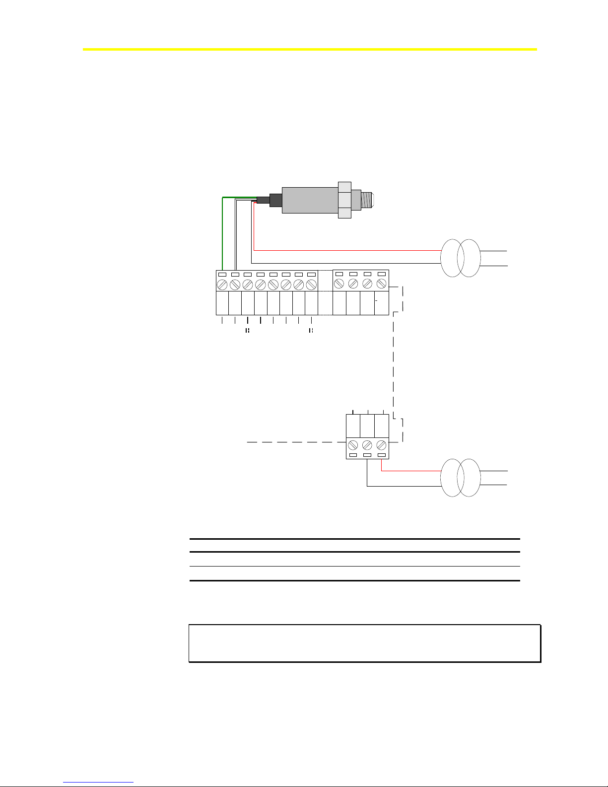
Connecting Active Sensors Powered by 24 VAC
The FX15 can accept active temperature, pressure, flow, and humidity
sensors providing 0-10 V or current signals powered by 24 VAC.
A second transformer (24 VAC/24 VAC, 3 VA maximum) powering
only the Analog Input is required in order to maintain the insulation
from the microprocessor.
35
Active Sensor
123
AGND
AI1
EXT V
45
AGND
67
AI2
8
AI3
AGND
FX16
FX15
powered at 24 V
32 33 34 35
EXT V
Earth
3 VA max
24 Vac
V ~ Com
V ~ Hot
24V
24V
939291
24 Vac
220Vac24 Vac
15 V
Figure 35: Active Sensor powered at 24 VAC Connection Diagram
Table 6: Active Sensors Powered by 24 VAC
FX15 Terminals Sensor Cable Description
AGND (1)
AI1 (2)
Green Common Reference
White Signal Output
Note: The numbers between the brackets are the FX15 terminal
numbers.
IMPORTANT: Not powering the Analog Input with a second transformer or
powering the AI with the power supply on another FX controller, will result in a
short circuit causing the failure of the FX15.
Page 36
FX15 Controller Technical Bulletin
A
36
Digital Inputs
The FX15 features eight opto-isolated digital inputs from potential free
contacts. A digital input is active depending on its polarity setting. The
default setting is Direct, which means that it is active (true) when
closed.
I/O Technical Details for the complete FX15 I/O table.
See
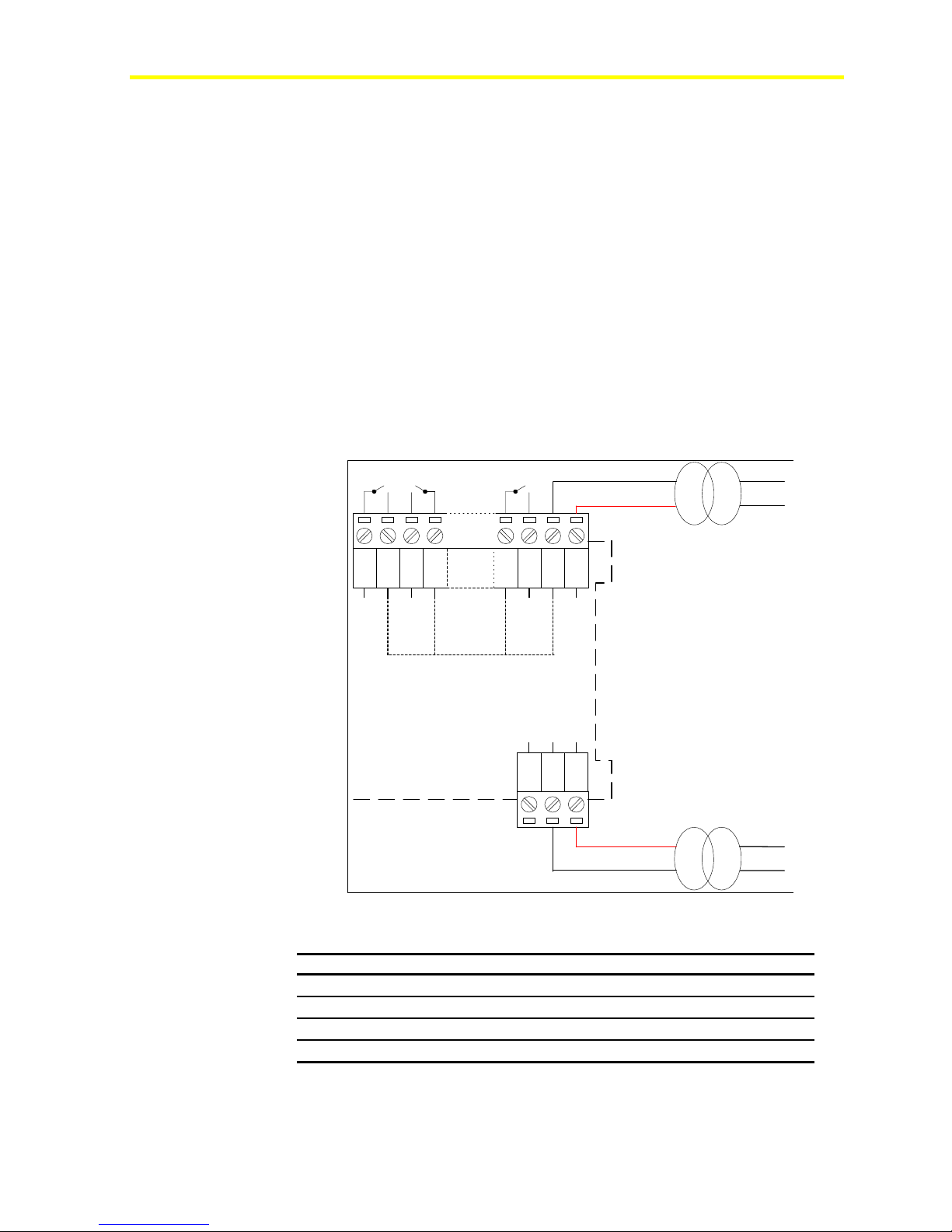
Digital Inputs Powered by 24 VAC
The eight FX15 Digital Inputs must be 24V powered, through terminals
34 and 35, both AC or DC voltage can be used, if DC is used then the
power supply of the DIs will have to be necessarily independent from
the controller power supply, being the FX15 compatible with VAC
power only. The digital inputs can use the same FX15 voltage supply or
they can be separately powered, in order to maintain the microprocessor
opto-isolation from the controller voltage supply.
220Vac24 Vac
3 VA max
3221
DICom
DI8
DI V ~ Com
DI V ~ Hot
24V
V ~ Hot
V ~ Com
Earth
939291
15 V
220Vac24 Vac
DI1
242322 33 34 35
DI2
DICom
DICom
FX16
FX15
Figure 36: Powering Digital Inputs Maintaining Opto-Isolation
Table 7: Digital Inputs Powered by 24 VAC
FX15 Terminals Description
DI V ~ Hot (35)
DI V ~ Com (34)
DI8 (33)
DICom (32)
24 VAC, Digital Inputs Power Supply
Digital Inputs Power Supply Common
Digital Input 8, Voltage-Free contact
Common Reference, Voltage-Free contact
Note: The numbers between the brackets are the FX15 terminal
numbers.
Page 37
FX15 Controller Technical Bulletin
Using Analog Inputs as Digital Inputs
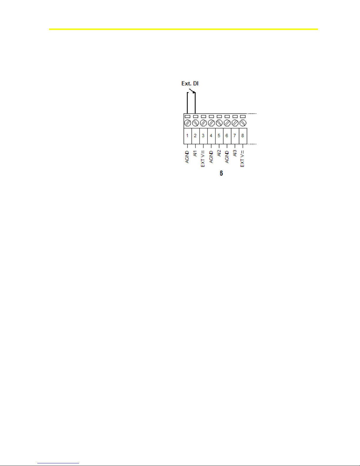
In case the user needs more than the 8 digital inputs available, the FX15
allows you to use an analog input as digital input.
37
Analog Outputs
FX15
Figure 37: Digital Input Connection Diagram
The Analog Input needs to be properly configured in FX Tools to read
the digital input.
The FX15 provides up to four, 0-10 VDC, 2A maximum, opto-isolated
analog outputs. The Analog Output objects provide the interface
between the four hardware Analog Output channels and the control
application. See I/O Technical Details at page 54 for the complete
FX15 I/O table.
The analog outputs can be configured for direct or reverse acting in the
application software.
The output signal can be limited by high limit (MaxOutput) and low
limit (MinOutput) values.
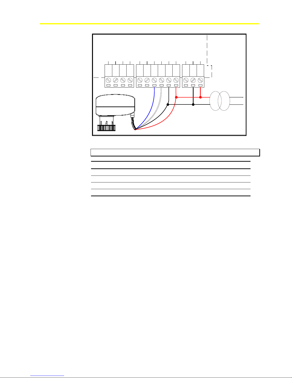
Powering and Connecting the Analog Outputs
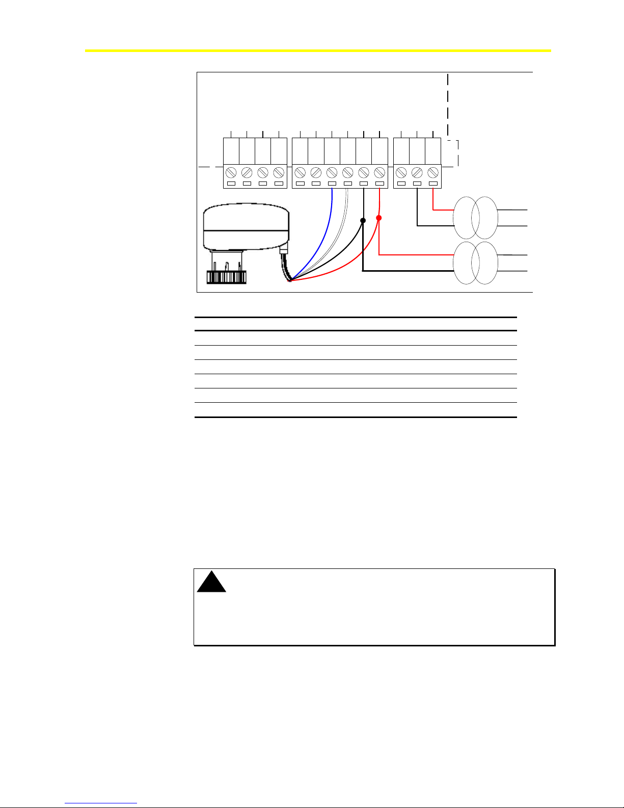
The analog outputs can be separately powered, through Terminals 79
and 80, in order to ensure microprocessor isolation from the controller
power supply (see Figure 39).
The FX15 analog outputs are commonly used to drive proportional
devices and can be connected to all the Johnson Controls Proportional
Valve Actuators.
The following figure represents the connection diagram.
Page 38
FX15 Controller Technical Bulletin
38
AO Com
AO1
AO Com
FX16
AO2
24V
AO Com
AO3
AO Com
AO4
AO V ~ Com
AO V ~ Hot
Earth
V ~ Com
V ~ Hot
71
75
747372
787776
8079
91
9392
15 VA
220Vac24 Vac
Figure 38: Connecting the Analog Output without Opto-isol ation
IMPORTANT: Make sure to respect connection polarities.
FX15 Terminals Description
AO Com (77)
AO4 (78)
AO V~ Com (79)
AO V~ Hot (80)
Common Reference
Analog Output 0-10 V
Common Reference
Power Supply 24 VAC
Note: The numbers between the brackets are the FX15 terminal
numbers.
The insulation from the microprocessor is achieved if a different 24
VAC power supply from the one used to power the controller is used to
power the analog outputs (through Terminals 79 and 80).
Page 39
FX15 Controller Technical Bulletin
A
FX16
24V
AO Com
AO Com
AO1
AO2
AO Com
AO3
AO Com
AO4
AO V ~ Com
AO V ~ Hot
V ~ Com
Earth
V ~ Hot
39
71
75
747372
787776
8079
91
9392
3 V
220Vac24 Vac
220Vac24 Vac
15 VA
Figure 39: Separately Powering Analog Outputs
FX15 Terminals Description
AO Com (77)
AO4 (78)
AO V~ Com (79)
AO V~ Hot (80)
V~ Hot (93)
V~ Com (92)
Common Reference
Analog Output 0-10 V
AO Common Reference
AO Power Supply 24 VAC
FX15 Power Supply 24 V
FX15 Common Reference
Note: The numbers between the brackets are the FX15 terminal
numbers.
Digital Outputs
The FX15 features 9 digital outputs, available in two hardware
configurations: all 9 Relays or 4 Relays and 5 triacs.
The Digital Outputs can be configured for direct acting or reverse acting
in the application software.
!
WARNING: Risk of Electric Shock and Property Damage.
Disconnect each of multiple power supplies before making electrical
connections. More than one disconnect may be required to completely
de-energize equipment. Contact with components carrying hazardous voltage
can cause electric shock and may result in severe personal injury or death.
Connecting the Relays
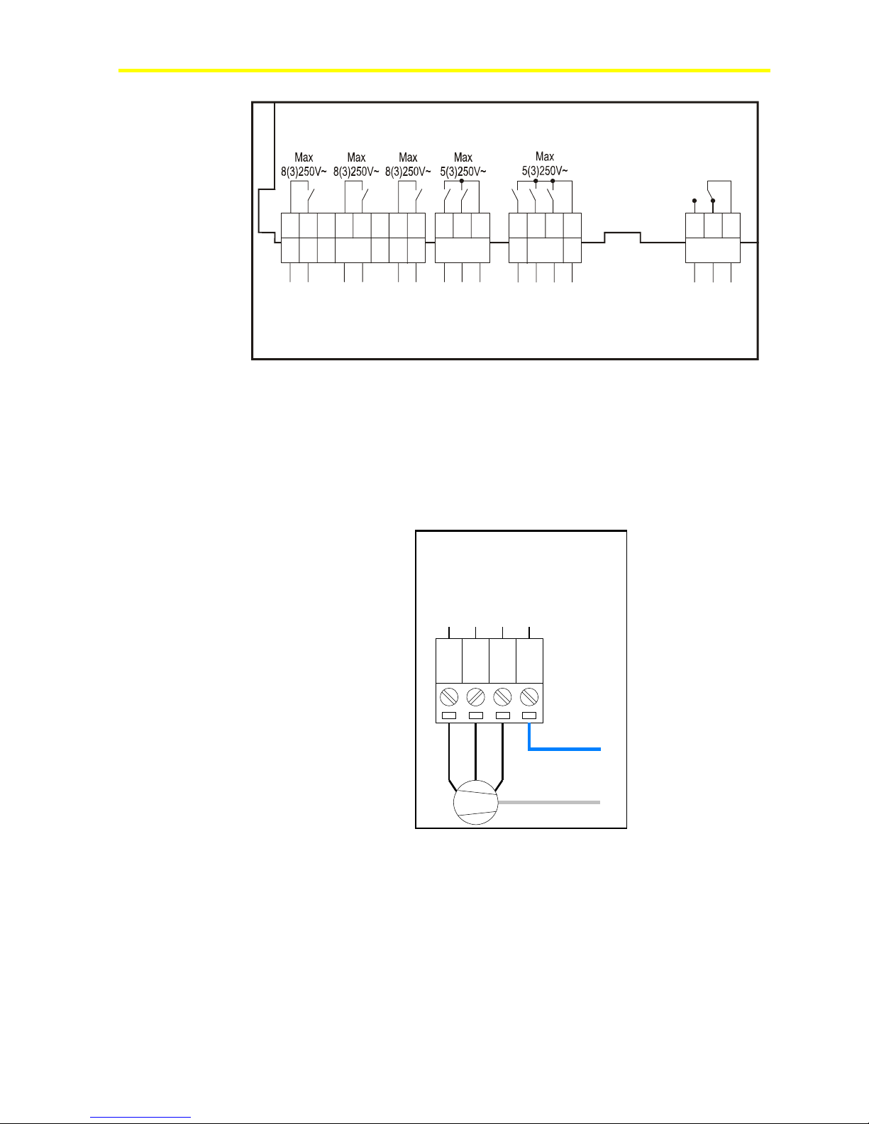
The FX15 features up to nine Digital Outputs with electromechanical
relays. To simplify assembly, the common terminals of some relays
have been grouped together. The relays are divided into six groups,
according to the distance of insulation.
Page 40
FX15 Controller Technical Bulletin
40
41 51 55 6242 52 56 6343 53 5754 6144 45 46 47 48
Group #6Group #5Group #4Group #3Group #2Group #1
Max
8(3)250V~
TB6
FAI L no
FAIL nc
DO1 no
DO1 Com
FX16-026_11 2003
TB3
DO2 Com
DO2 no
TB5TB4
DO4 no
DO3 no
DO3 Com
DO5 no
DO4/5 Com
DO7 no
DO8 no
DO6 no
DO6/7/8 Com
Figure 40: Relay Groups
Inside each group, the relays have just single isolation and thus must be
connected to the same voltage supply. Between the groups, there is a
double isolation and thus the groups can be connected to different
voltage supplies.
Figure 41 displays a typical application of the relay outputs as
connection example.
DO6 no
54
DO7 no
DO 6/7/8 Com
DO8 no
575655
FAIL Com
Note: Relays DO6-DO8 are not hardware interlocked and incidental
energization of more than one relay at the same time might lead to fan
motor damaging.
N
Speed2
Speed1
Fan
Speed3
~ 230Vac
L
Figure 41: Connecting a Three-Speed Fan Motor
Page 41
FX15 Controller Technical Bulletin
Connecting the Triacs
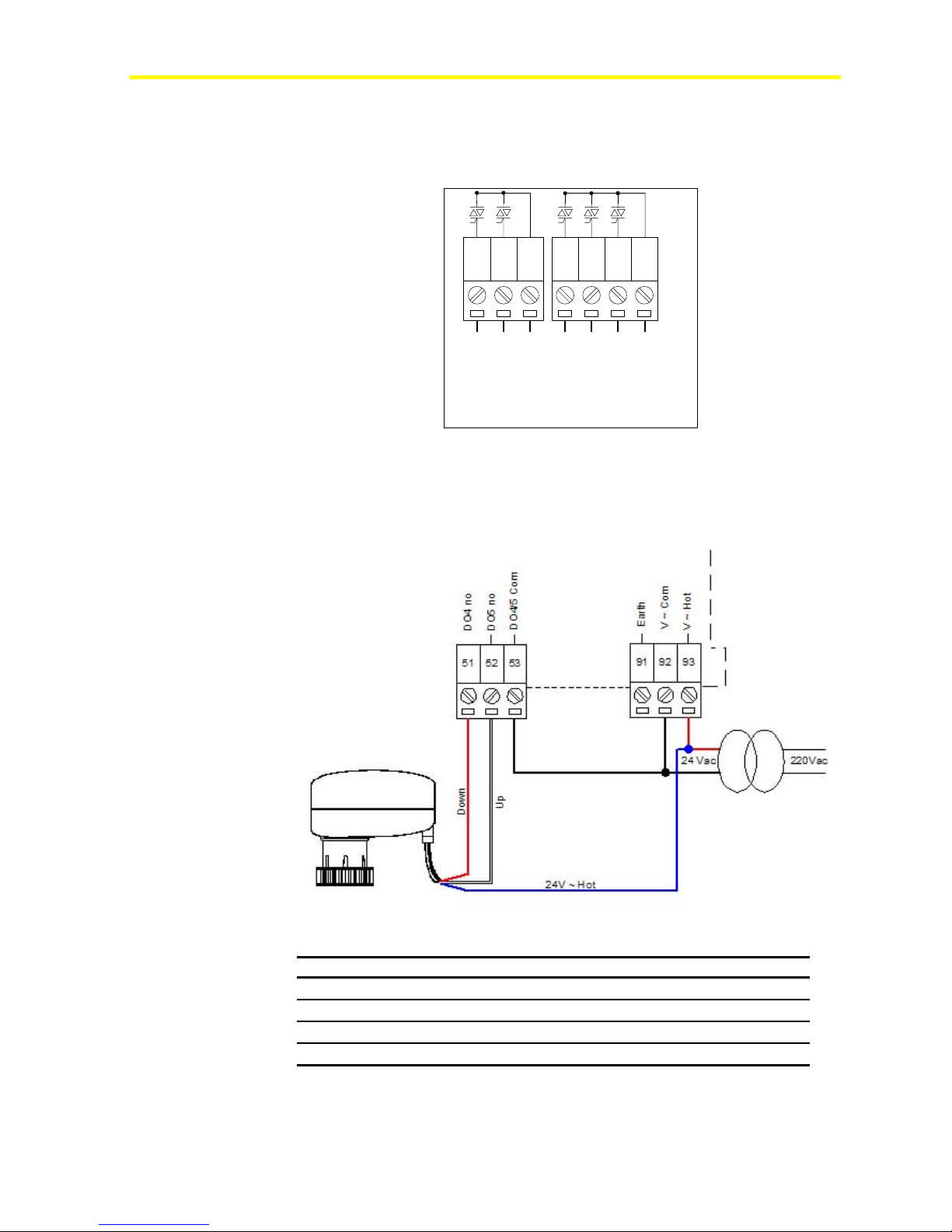
The FX15 triac (0.5 A, 24 VAC) digital outputs are commonly used to
operate in PAT and DAT modes.
54 575655535251
41
DO3 no
DO4 no
DO6 no
DO 4/5 Com
DO7 no
DO8 no
DO 6/7/8 Com
Figure 42: Triac Groups
In particular the Digital Outputs PAT mode can be used through the
triac outputs to drive Incremental Valve Actuators.
Figure 43 displays an example of a triac connection.
FX15 Terminals Description
DO4 (51)
DO5 (52)
V ~ Hot (93)
DO 4/5 Com (53)
Note: Between round brackets are reported the FX15 terminal
numbers.
Figure 43: Connecting an Incremental Actuator
24V ~ Down command
24V ~ Up command
24V ~ Hot Reference
24V ~ Common Reference
Page 42

FX15 Controller Technical Bulletin
42
Extension Modules
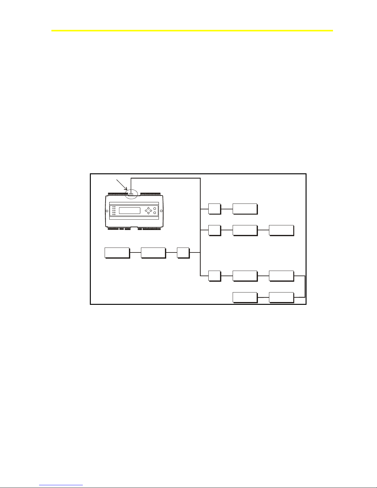
The input/output capacity of the FX15 may be extended by connecting
up to four extension modules via the Extension Bus (XT-Bus,
terminal J1).
An extension module if formed by an XT91D00
processor/communications module and one or more XP expansion
modules. The expansion modules provide input/output capability for the
extension modules. The following are available for the XT91D00
extension module:
• XP91D02: six analog inputs and two analog outputs
• XP91D03: eight digital outputs (triac)
• XP91D04: four digital inputs and four digital outputs (triac)
• XP91D05: eight digital inputs
• XP91D06: four digital outputs 230 VAC (relay) (EU only)
• XP91D07: four digital outputs 24 VAC (relay) (NA only)
Analog inputs to extension modules may be 0-10 V, 0-20 mA or
passive RTD-Ni1000 (Johnson Controls characteristic only), Pt1000 or
A99 sensors.
Analog inputs to the XPA-421-5 module only may additionally be
RTD-Ni1000 (LandG and DIN), Pt100 and NI100 sensors or a 5 K ohm
potentiometer.
Voltage and current inputs from differential pressure transducers can
be linearized by a square root function.
Digital inputs to extension modules are potential-free contacts.
The input is active (true) when the contact is closed.
Digital counters are available in extension modules, which do not have
analog inputs or outputs. Digital counters are associated with digital
inputs. The number of positive transitions of the physical digital input
required to increment the counter can be programmed in the extension
module.
Note: Counter values are saved in EEPROM by XT/XP only at the
power down, in the particular situation of an application downloading to
the FX15 the increments occurred from the last XT/XP power-up and
the download are lost. The problem can be overcome if a power down
of the XT/XP module of interest is executed right before proceeding
with the program download.
Analog outputs in extension modules can be configured to provide
0-10 V, 0-20 mA or 4-20 mA signals. The output is ranged by low
range and high range variables to provide a 0-100% signal to the
extension module.
Page 43
FX15 Controller Technical Bulletin
X
X
X
X
X
Digital outputs in extension modules can only be configured as on/off
or pulse type, and the physical output may be a triac or a relay contact.
Pulse type outputs switch on for a configurable period (1 to 1275 ms)
for each transition of the connected variable.
An XT91D00 can be combined with its expansion modules to provide
the following configurations:
• 8 analog inputs/outputs
• 8 digital inputs/outputs, with digital counters associated with the
digital inputs
• 8 analog inputs/outputs and eight digital inputs/outputs
• 16 digital inputs/outputs, with digital counters associated with the
digital inputs within the first eight input/output points
Extension Bus (J1)
43
FX15 "Classic"
FX15-C-007_ 10 2002
XT
XT
XP-9103XP-9104
XT
T
P-9102
P-9103
P-9103
P-9107
Figure 44: Example of Maximum Configuration
XP-9103
XP-9103
XP-9107
Page 44

FX15 Controller Technical Bulletin
44
Troubleshooting
Reading 9999 or Invalid from the Analog Inputs
• Error/Condition: The Analog Input object retrieves an Invalid
value through network variables or the User Interface Unit shows
9999 or Invalid customized tag;
• Problem: Happens in the case the signal applied to the Analog
Input channel does not match with the one configured via software
on the Analog Input Object. The read signal is outside the
configured reliability range. The problem can be due to the Jumper
configuration of the Analog Input channel which can not be set
according to the signal provided by the sensor;
• Solution: In case the signal does not match with the configured,
change the Analog Input Object configuration via FX Builder. If the
software is properly configured but the problem still happens, check
the analog inputs jumpers are properly set in order to accept the
sensor signal and verify the probe functioning and wirings.
Can Not Properly Read Current Sensors
• Error/Condition: Connecting an active, current sensor to an
Analog Input channel, the AI Object retrieves an Invalid value;
• Problem: In the case the AI Object is properly configured and the
probe is correctly wired and functioning, the problems may be due
to a wrong AI Jumper configuration;
• Solution: A dedicated Jumper is placed on board for each Analog
Input Channel. This Jumper is used in its close configuration in the
case the connected sensor provides a Current signal (0-20/4-20 mA).
Its open configuration has t o b e used for R e s i stiv e , R a tio- M e t r ic or
Volt a g e ( 0 - 2 / 0 - 1 0 V ) input signals.
Page 45

FX15 Controller Technical Bulletin
Operation
Introduction
The FX15 is a high performance field controller and it has been
designed to respond to a wide range of applications including dual
compressor chillers and rooftops, close control units, packaged air
handling units, unit vents, and water source heat pumps.
The FX15 has 27 physical input/output points on board and can be
further expanded by connecting the XT91D00/XP91Dxx Series
expansion modules.
Parameters in the control application can be displayed and modified
from the optional user interface.
45
Page 46

FX15 Controller Technical Bulletin
46
Key Concepts
Software Programming and Application Configuration
The FX15 provides configurable control algorithm, memory and
connectivity services, real-time functions, and I/O expansion through its
customizable, objects and services oriented, architecture. The device
configurations can be created and downloaded into the target controllers
via the FX Tools Pro software package.
The tools available in the package are:
• FX Builder: The programming and configuration of the Facility
Explorer controllers is done using the menus, navigation trees, and
graphic screens of the FX Builder tool. The configuration includes
the definition of the controllers to be connected, the physical inputs
and outputs and data points to be monitored and the format of the
display screen of the controller.
• FX Builder Express: A simplified version of the FX Builder, called
FX Builder Express, is also available to configure a library of
standard applications specifically designed for Facility Explorer
controllers. The configuration is done using the specific graphic user
interfaces of the FX Builder Express.
• FX CommPro N2/LON: Parameter configuration, machine tuning,
default parameters saving for successive configurations are all
things possible with the FX CommPro tool with 2 protocols
supported: N2 Open, LONWORKS.
Alarm and Event Management
The FX15 manages and records events or alarms that are associated with
data points or variables in the control application.
The table of active events and the event history log may be viewed on
the user interfaces.
Time Scheduling
This feature allows introducing functions based on a weekly time
schedule. The clock is battery backed up with an average duration time
of 2 years.
User Interfaces
The FX15 can have different user interface options (integrated, local, or
remote) proving the possibility to display and edit all the data point and
information of the running a pplicatio n. The u ser interfac e is fully
configurable at design time.
Page 47

FX15 Controller Technical Bulletin
Security
The FX Tools and the FX controllers come with an embedded security
features based on the use of two IDs: the Family ID and the Customer ID.
This security feature prevents tampering with the applications and provides
source code protection.
Supervisory Option
The FX15 can be integrated into a supervisory building automation
system for continuous monitoring of the control system. The FX15
supports two methods of integration:
• N2 Open Integration
• LONWORKS Integration
Application Upload/Download
The FX15 is a fully programmable controller and the application can be
downloaded to the controller with the FX Tools or
uploaded/downloaded via Programming Key.
47
Page 48
FX15 Controller Technical Bulletin
48
User Interface
The FX15 can be connected to up to 2 remote user interfaces with the
possibility to display/edit all the data point and information of the
running application. The user interface application is fully configurable
at design time. The user interface must be of the same type. The user
interfaces are optional, which means that the controller can work also
without any display plugged-in.
The configuration is integrated, local, for example: panel mount (up to
3 m [9.8 ft]) or remote, for example: wall mount (up to 1km [0.6 mi]):
• integrated: directly plugged on top of the controller
• local: up to 3 m (9.8 ft) from the controller, power supply and data
communication via the flat telephone cable included in the
LP-KIT007-000C
• remote: up to 300 m (984 ft) from the controller.
The display must be independently powered; the data
communication is done via a 3 pole shielded cable (not provided)
connected to the Remote Display Connection of the FX15.
The FX15 can support 1 integrated user interface or 1 panel mount or
wall mount user interface or 1 panel mount display + 1 wall mount user
in or 2 wall mount ones. For the panel mount connection use the
pre-cabled connection kit (LP-KIT007-000C), 3 m (9.8 ft) long, with a
phone jack on the MUI side and a preassembled screw connector on the
FX15 side.
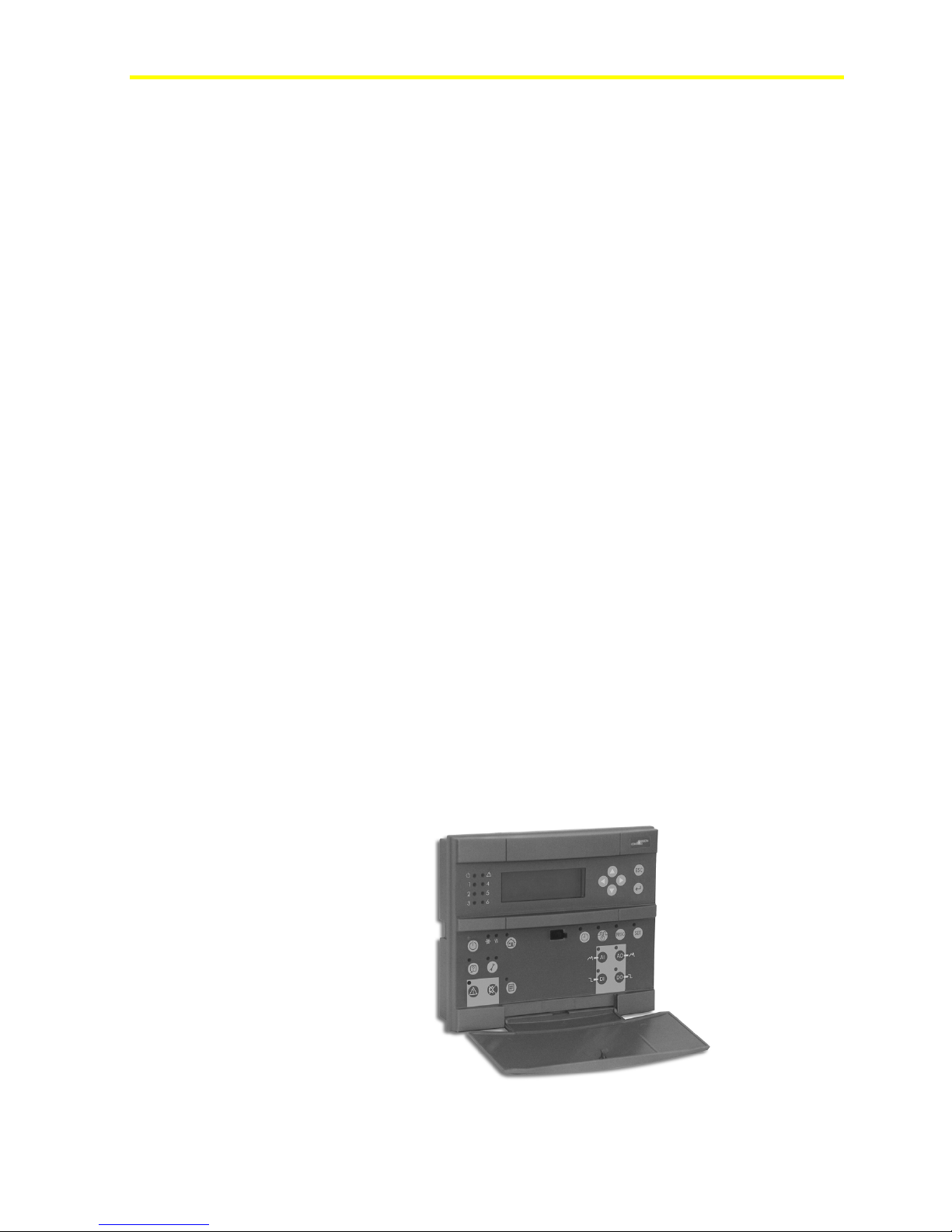
The user interface models connectable to the FX15 are:
• LP-DIS65P10-0C: Large User Interface (LUI), panel, flush mount
or hand held, 4x20 backlit LCD, IP54, extended temperature range:
-20 to +50°C (68 to 122°F), standard JCI front-plate. The
front-plate is fully customizable upon minimum order.
Figure 45 : Large User Interface (LUI)
Page 49
FX15 Controller Technical Bulletin
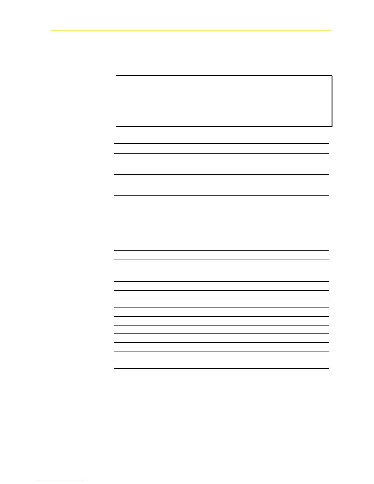
• LP-DIS60U10-C: Integrated Medium User Interface, Integrated,
4x20 backlit Lighting Control Data (LCD), IP54, extended
temperature range: -20°C (68°F) to +50°C (122°F)
Figure 46 : Integrated Medium User Interface (MUI)
• LP-DIS60P10-0C/LP-DIS60P11-0C: Medium User Interface, 4x20
backlit LCD, IP54, extended temperature range: -20°C (68°F) to
+50°C (122°F). Panel mount, non-isolated version, and wall mount
isolated version
49
Figure 47 : Medium User Interface (MUI)
For more details about the connection possibilities, refer to the specific
user interface technical bulletin.
Page 50

FX15 Controller Technical Bulletin
50
Security
The FX Tools Pro and the Facility Explorer controllers come with an
embedded security feature based on the use of two IDs: the Family ID
and the Customer ID.
Family ID
Family ID differentiates different hardware types and prevents the
downloading of the wrong application to the wrong controller.
Table 8: Family ID
Facility Explorer
Controller
FX05 Advanced
FX10 Standard
FX10 Advanced
FX15
FX15 Universal
FX Builder Code Family IDs
FX05P11-02 0218
FX05P11-12 0210
FX05P11-22 0211
FX05P12-02 0212
FX05P12-12 0214
FX05P12-22 0215
FX05P13-02 0213
FX05P13-12 0216
FX05P13-22
FX10B1x
FX10B3x
FX15D1x
FX15D0x
0217
0301
0311
0402
0401
Customer ID
Customer ID protects a controller downloaded with a custom developed
application and protects the application source code from editing by
unauthorized users. Three Customer ID types are used:
• Public ID: applications that are saved with Public ID can be
downloaded and commissioned by any user with the Public ID
enabled in FX Tools.
• Demo ID: applications that are saved with the Demo ID can only be
downloaded to demo controllers.
• Customer/Private Specific ID: Applications that are saved with a
specific customer/private ID will make those applications source
files readable only by users who have the same ID enabled in FX
Tools. Once a controller has been downloaded with a specific
Customer ID, the controller will become customer specific and only
allow downloading of application with the same customer specific
ID.
Page 51

FX15 Controller Technical Bulletin
51
Specifications and Technical Data
Ordering Codes
Table 9: FX15 Controller
Ordering Codes Description
LP-FX15D10-000C
LP-FX15D11-000C
LP-FX15D12-000C
LP-FX15D60-000C
LP-FX15D61-000C
LP-FX15D62-000C
LP-FX15D20-000C
LP-FX15D21-000C
LP-FX15D22-000C
LP-FX15D70-000C
LP-FX15D71-000C
LP-FX15D72-000C
FX15, 4 Relays + 5 triacs, without the application
FX15, 4 Relays + 5 triacs, N2 Open card preassembled,
without the application
FX15, 4 Relays + 5 triacs, L
without the application
FX15, 4 Relays + 5 triacs, integrated MUI display, without the
application
FX15, 4 Relays + 5 triacs, N2 Open card preassembled,
integrated MUI, without the application
FX15, 4 Relays + 5 triacs, L
integrated MUI, without the application
FX15, 9 Relays, without the application
FX15, 9 Relays, N2 Open card preassembled, without the
application
FX15, 9 Relays, L
application
FX15, 9 Relays, integrated MUI display, without the
application
FX15, 9 Relays, N2 Open card preassembled, integrated MUI,
without the application
FX15, 9 Relays, L
MUI, without the application
ONWORKS card preassembled, without the
ONWORKS card preassembled, integrated
Table 10: FX15 Extended Range Controller
Ordering Codes Description
LP-FX15X10-000C
LP-FX15X11-000C
LP-FX15X12-000C
LP-FX15X20-000C
LP-FX15X21-000C
LP-FX15X22-000C
FX15, 4 Relays + 5 triacs, without the application
FX15, 4 Relays + 5 triacs, N2 Open card preassembled,
without the application
FX15, 4 Relays + 5 triacs, L
without the application
FX15, 9 Relays, without the application
FX15, 9 Relays, N2 Open card preassembled, without the
application
FX15, 9 Relays, L
the application
ONWORKS card preassembled, without
ONWORKS card preassembled,
ONWORKS card preassembled,
ONWORKS card preassembled,
Table 11: Communication Card
Ordering Codes Description
LP-NET151-010C
LP-NET152-010C
N2 Open communication card
ONWORKS communication card. On-field commissioning
L
Page 52

FX15 Controller Technical Bulletin
52
Table 12: User Interface Displays
Ordering Codes Description
LP-DIS65P10-0C
LP-DIS60P10-0C
LP-DIS60P11-0C
LP-DIS60U10-C
Table 13: Accessories
Ordering Codes Description
LP-KIT007-000C
LP-KIT015-000C
LP-KIT015-001C
LP-KIT100-000C
DT-9100-8901
LP-KIT100-001C
Large User Interface V.2, (4x20 character) LCD backlit
display (LUI with std JCI front plate)
Medium User Interface V.2, (4 x20 character) LCD backlit
display, panel mount version
Medium User Interface V.2, (4 x20 character) LCD backlit
display, wall mount isolated version
Integrated MUI, (4 x 20) LCD backlit display for FX15
Link cable for the connection of the FX15 to the MUI/LUI
display -3m (19 ft)
Kit of female screw connectors
Kit of female cage clamp connectors
FX Programming Key
Power Supply for Programming Key and LUI: 230 VAC/12
VDC
Power Supply for Programming Key and LUI: 230 VAC/12
VDC
Table 14: Room Command Modules Available Only in Europe
Ordering Codes Description
LP-TR23024-10VA
LP-KIT006-000C
LP-KIT006-001C
LP-KIT006-002C
LP-KIT006-003C
Transformer for FX05, 10 VA
Room Sensor module for FX05 +/- dial, occupancy button,
fan speed, service port
Room Sensor module for FX05 12-28°C dial
Room Sensor module for FX05 12-28°C dial, occupancy
button, service port
Room Sensor module for FX05 +/- dial, occupancy button,
service port
Table 15: Room Command Modules Available Only in North America
Ordering Codes Description
LP-KIT006-004C
LP-KIT006-005C
LP-KIT006-006C
LP-KIT006-007C
Room Sensor module for FX05, warm/cool adjustment
dial, occupancy button, fan speed selector switch, service
port, US mounting kit
Room Sensor module for FX05 warm/cool adjustment dial,
occupancy button, US mounting kit
Room Sensor module for FX05 setpoint (54-82°F)
adjustment dial, occupancy button, fan speed selector
switch, service port, US mounting kit
Room Sensor module for FX05 setpoint (54-82°F)
adjustment dial, occupancy button, service port, US
mounting kit
Page 53

FX15 Controller Technical Bulletin
Table 16: Expansion Modules
Ordering Codes Description
LP-XT91D00-000C
LP-XP91D02-000C
LP-XP91D03-000C
LP-XP91D04-000C
LP-XP91D05-000C
LP-XP91D06-000C
LP-XP91D07-000C
Extension module
Expansion board: 6 AI, 2 AO
Expansion board: 8 DO (triacs)
Expansion board: 4 DI, 4 DO (triacs)
Expansion board: 8 DI
Expansion board: 4 DO (relays) 230 VAC (Europe
only)
Expansion board: 4 DO (relays) 24 VAC (North
America only)
Table 17: Demo Cases and Controllers
Ordering Codes Description
DEMO-FX15-071
DEMO-FX15-072
DEMO-FX15-081
DEMO-FX15-082
LP-FX15DEM-010C
LP-FX15DEM-011C
Demo case FX15 + N2 Open communication, 230 V
Demo case FX15 + LON communication, 230 V
Demo case FX15 + N2 Open communication, 120 V
Demo case FX15 + LON communication, 120 V
FX15 controller + Integrated display + N2 Open
comm. Card with DEMO ID
FX15 controller + Integrated display + LON comm
Card with DEMO ID
53
Table 18: Software
Ordering Codes Description
LP-FXTPRO-0
LP-FXTEXP-0
FX Tools Pro CD-Rom (FX Builder, FX Builder
Express, FX CommPro N2, FX CommPro LON)
FX Tools Express CD-Rom (FX Builder Express, FX
CommPro N2)
Page 54
FX15 Controller Technical Bulletin
54
Technical Specifications
I/O Technical Details
IMPORTANT: For installation with Class 2 inputs and outputs only, no
special mounting precautions are generally necessary. For use with one or
more line voltage outputs (above 30 V), installation as part of a UL 508A
industrial control panel may be required by the local building or electrical
authority. These controllers are presently UL Recognized as Temperature
Indicating and Regulating Equipment in accordance with UL 873. UL Listing as
Open Energy Management Equipment per UL 916 is pending.
Table 19: Analog Input (AI)
Terminals Channel Type Remark/Application
TB1 (1-15)
TB1 (3, 8)
TB1 (13)
List of Available Sensor Input
Sensor Type Linearization Range Accuracy
Ni1000 JCI
Ni1000 JCI Extended
Ni1000 Siemens™
Ni1000 DIN
Pt1000
A99
NTC 2.2K
0 to 5 VDC ratiometric
0 to 10 VDC
0 to 20 mA
AI1, AI2, AI3,
AI4, AI5, AI6
EXT-VDC +16 V, 80 mA Directly power from the
AVPS/EXTVDC
Figure 30. Software configurable.
See
Application: temperature,
humidity, pressure
controller. Maximum four
0-20/4-20 mA sensors
AVPS = +5 V, 20 mA
EXT-VDC = +16 V, 80
mA
To directly power
ratiometric sensors,
with AVPS or
0-10 V, 0/4 - 20 mA
Sensors with EXT-VDC.
The selection between
AVPS and EXT-VDC is
done through jumpers.
@ 20°C (68°F)
ambient
-45 to 120 °C (-49 to 248°F) +/- 0.5° C (0.9°F)
20 to 287°C (68° to 548.6°F) +/- 0.5° C (0.9°F)
-50 to 160°C (-58 to 320°F) +/- 0.5° C (0.9°F)
-60 to 180°C (-76 to 356°F) +/- 0.5° C (0.9°F)
-50 to 605°C (-58°F to 1121°F) +/- 0.6° C (1.08°F)
-50 to 110°C (-58 to 230°F) +/- 0.5° C (0.9°F)
-40 to 150°C (-40 to 302°F) +/- 0.5° C (0.9°F)
10 to 90% of supply voltage 0.3%
0 to 10 Volts 0.3%
0 to 20 mA 0.3%
Page 55

FX15 Controller Technical Bulletin
Table 20: Digital Input (DI)
Terminals Channel Type Remark/Application
TB2 (21-33)
TB2 (34, 35)
DI1, DI2, DI3, DI4,
DI5, DI6, DI7, DI8
DI V~ Hot
DI V~ Com
Potential free
contacts
24 VAC/DC Power supply for the
Digital Inputs. Must be
used in order to maintain
the opto-isolation a
separate power supply
from the one used for the
controller.
Table 21: Digital Output (DO)
55
Terminal
TB3
TB4
TB5
TB6
Channel Type Remark/Application
DO1, DO2, DO3 SPST 8(3)A
power relays
DO4, DO5 SPST 5(3)A
power relays
or
0.5A/24 VAC
triacs
DO6, DO7, DO8 SPST 5(3)A
power relays
or
0.5A/24 VAC
triacs
DO9 SPDT NC
8(3)A 250V
relay
Maximum switching power:
2000VA, 240W, 0.5HP, 250
VAC
UL/CUR rating: 8A 250 VAC
8A 30 VDC
VDE rating: 8A 250 VAC
Expected electrical life min.
operations:
1 x 10⁵ operations (360 ops x
hour)
Dielectric strength:
coil-contacts 4000 Vrms
Maximum switching power:
1.250 VA, 150 W
Rating (resistive): 10 A
125 VAC, 5A 250 VAC, 5 A 30
VDC
Expected electrical life (min
operations):
10A 125 VAC 5x10⁴
5A 250 VAC 5x10⁴
5A 30 VDC 105
Dielectric strength:
coil-contacts 4000 Vrms
for 1 min
Same as TB3 relays
Fail relay for enhanced
security. The relay will return
to its NC position not only at
power fail but also in case the
microprocessor should fail:
watch-dog, brown-out, etc.
Page 56

FX15 Controller Technical Bulletin
56
Table 22: Analog Output (AO)
Terminals Channel Type Remark/Application
TB7
TB8
TB8 (79, 80)
AO1, AO2 0-10 VDC (maximum
AO3, AO4 0-10 VDC (maximum
AO V~ Hot
AO V~
Com
N2 Open Card
Table 23: N2 Open Card
RS-485 line
Devices
RS-485/232 Converter
Electrical Isolation
Used to drive motor
1.5 mA)
1.5 mA)
24 VAC Power supply for the Analog
Maximum length without repeater: 1200 m (4000 ft),
AWG26 twisted pair with shield.
Maximum of 32 per 1200 m (4000 ft) bus segment.
IU-9100 if third party converter is used then make
sure it supports automatic DSC (Data Send Control)
1500 V
actuators, power triacs,
frequency drives. 16-bit
resolution.
Used to drive motor
actuators, power triacs,
frequency drives. 16-bit
resolution.
Outputs. In order to maintain
the opto-isolation a separate
power supply from the one
used for the controller, must
be used.
LON Connection
Table 24: LON Connection
LON network and Line
Terminators
Nodes
Cable type:
Belden® 85102
Belden 8471
Level IV 22 AWG
Daisy chained Bus Topology: two terminators of 100
ohm required, one at each end of the bus.
Free (start) topology: single terminator of 50 ohm
required.
64 (if repeaters are not used),
FTT-10 nodes only.
Length with FTT-10 devices
Bus Topology Free Topology
2700 m (1.7 mi) 500 m (0.3 mi)
2700 m (1.7 mi) 500 m (0.3 mi)
1400 m (0.9 mi) 400 m (0.3 mi)
Page 57

FX15 Controller Technical Bulletin
Programming Key
Table 25: Programming Key
Power Supply
Memory type and size
Connection to controller
Enclosure IP class
Ambient Limits
Agency Listing
Directly powered from the Display Bus port of the
FX15 or from an AC/DC adapter 230V to 12
VAC ÷ 15 VDC min 2 VA
Flash memory 1 Mbytes
Via RS-485, not isolated, 10 cm cable provided
with the key
IP40
Operating: 0°C (32°F) – 40°C (104°F), 10-95% rH
(noncondensing)
Storage: -20°C (-4°F) – 70°C (158°F), 10-95% rH
(noncondensing)
73/23 EEC directive: EN 60730
FX15
Table 26: FX15
Product
Power Supply
Requirements
Power Consumption
Protection Class
Isolation
Ambient Operating
Conditions
Ambient Storage
Conditions
Dimensions (H x W x D)
Weight (with package)
I/O ratings
Connection terminals for
signals and power supply
LON/N2 Open bus
connection terminals
Connection terminals for
extension bus and remote
display
Continued on next page…
FX15
24 VAC ±15%, 50/60 Hz - Class 2 Power
Supply
15 VA at maximum load
IP20 controller
IP40 integrated MUI
See Isolation Diagram.
-20 to +50°C (-4 to 122°F), 10 to 95% rH
(noncondensing)
-20 to +70°C (-4° to 158°F), 10 to 95% rH
(noncondensing)
142 mm (5.6 in.) x 215mm (8.5 in.) x 49 mm
(1.9 in.)
0.74 Kg (1.6 lb)
I/O Technical Details.
See
Screw terminals for maximum 1 x 1.5 mm2
(0.002 in.
or
Cage clamp connectors 1 x 1.5 mm
wires
To be ordered separately
Screw terminals, cable size 0.05 to 1.5 mm
(0.002 in.2), AWG30 to AWG14
Belden cable, 2-core twisted pair with shield
Screw terminals, cable size 0.05 to 1.5 mm
(0.002 in.2), AWG30 to AWG14
2
) wires
2
(0.002 in.2)
2
2
57
Page 58

FX15 Controller Technical Bulletin
58
Single cable lengths
Digital Inputs DI1 - DI8
Analog Inputs AI1 - AI6
Triac outputs (when present)
Analog Outputs AO1 - AO4
Remote Display
Extension Modules
Display and Extensions
cable type
Compliance
United States: FCC Compliant to CFR 47, Part
UL compliance
FX15 Extended Range
Table 27: FX15 Extended Range
Product
Power Supply Requirements
Power Consumption
Protection Class
Isolation
Ambient Operating
Conditions
Ambient Storage Conditions
Dimensions (H x W x D)
Weight (with package)
I/O ratings
Connection terminals for
signals and power supply
LON/N2 Open bus connection
terminals
Connection terminals for
extension bus and remote
display
Continued on next page…
Maximum 100 m (328.1 ft) with diameters ≥ 0.6
mm (0.02 in.)
Maximum 100 m (328.1 ft) with diameters ≥ 0.6
mm (0.02 in.)
Maximum 100 m (328.1 ft) where A ≥ 1.5 mm
(0.002 in.2)
Maximum 100 m (328.1 ft) where A ≥ 1.5 mm
(0.002 in.2)
Maximum 3 m (9.8 ft) if display is powered by
controller. Maximum 1km (1.9 mi) if display
independently powered
Maximum 1km (0.6 mi)
Belden 4-core, twisted pair, shielded
89/336 EEC directive: EN 50081-1
(EN 61000-6-3), EN 50082-1 (EN 61000-6-1)
73/23 EEC directive: EN 60730
15, Subpart B, Class A
Canada: Industry Canada, ICES-003
UL873 Recognized (XAPX2, XAPX8)
FX15 extended range
24 VAC ±15%, 50/60 Hz - Class 2 Power
Supply
15 VA at maximum load
IP20 controller
IP40 integrated MUI
See Isolation Diagram.
-40 to +60°C (-40 to 140°F), 10 to 95% rH
(noncondensing)
-20 to +70°C (-4 to 158°F), 10 to 95% rH
(noncondensing)
142 mm (5.6 in.) x 215 mm (8.5 in.) x 49 mm
(1.9 in.)
0.74 Kg (1.6 lb)
See
Screw terminals for a maximum 1 x 1.5 mm2
(0.002 in
Screw terminals, cable size 0.05 to 1.5 mm
(0.002 in.2), AWG30 to AWG14, included in
the package.
Belden cable, 2-core twisted pair with shield
Screw terminals, cable size 0.05 to 1.5 mm
(0.002 in.2), AWG30 to AWG14, included in
the package.
I/O Technical Details.
2
) wires, included in the package.
2
2
2
2
Page 59

FX15 Controller Technical Bulletin
59
Single cable lengths
Digital Inputs DI1 - DI8
Analog Inputs AI1 - AI6
Triac outputs (when present)
Analog Outputs AO1 - AO4
Remote Display
Extension Modules
Display and Extensions cable
type
Maximum 100 m (328.1 ft) with diameters ≥
0.6 mm (0.02 in.)
Maximum 100 m (328.1 ft) with diameters ≥
0.6 mm (0.02 in.)
Maximum 100 m (328.1 ft) where A ≥ 1.5 mm
(0.002 in.2)
Maximum 100 m (328.1 ft) where A ≥ 1.5 mm
(0.002 in.2)
Maximum 3 m (9.8 ft) if display is powered by
controller. Maximum 1 km (1.9 mi) if display
2
2
independently powered
Maximum 1km (0.6 mi)
Belden 4-core, twisted pair, shielded
Compliance
89/336 EEC directive: EN 50081-1
(EN 61000-6-3), EN 50082-1 (EN 61000-6-1)
73/23 EEC directive: EN 60730
United States: FCC Compliant to CFR 47,
Part 15, Subpart B, Class A
Canada: Industry Canada, ICES-003
UL compliance
The performance specifications are nominal and conform to acceptable industry standards. For
application at conditions beyond these specifications, consult the local Johnson Controls office. Johnson
Controls, Inc. shall not be liable for damages resulting from misapplication or misuse of its products.
UL873 Recognized (XAPX2, XAPX8)
Controls Group Global Headquarters
507 E. Michigan Street
P.O. Box 423 Published in U.S.A. and Europe
Milwaukee, WI 53201
 Loading...