

Page 1

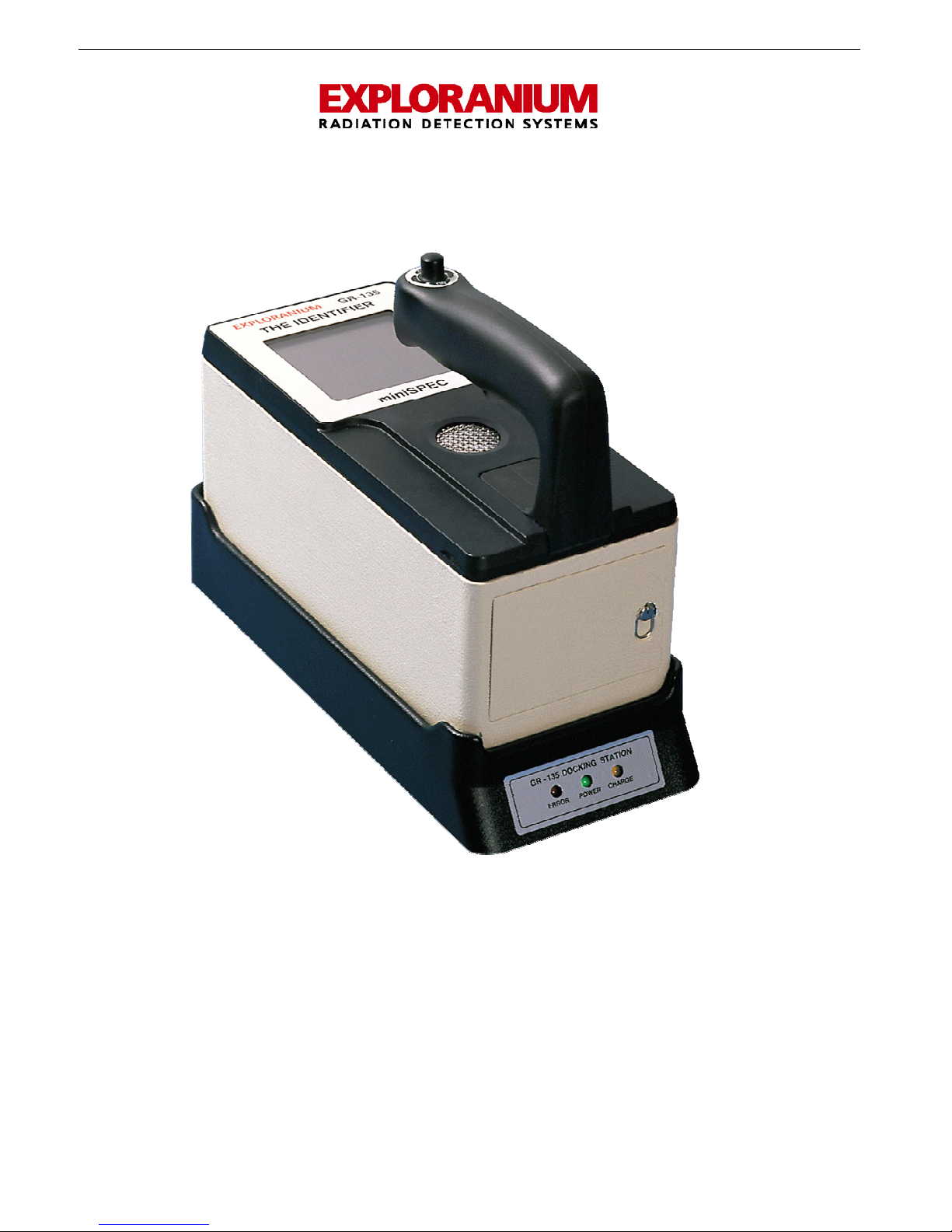
GR-135
THE IDENTIFIER
SYSTEM MANUAL
Part #87317-1 Rev.3.4
July 2004
Page 2

SAIC Exploranium – GR-135 System Manual page: 2
GR-135
THE IDENTIFIER
SYSTEM MANUAL
Table of Contents
1.0 GENERAL SYSTEM DESCRIPTION:....................................................................................6
1.1 GR-135 HARDWARE VERSIONS ....................................................................................6
1.2 GR-135 OPERATIONAL MODES.....................................................................................6
1.3 SOFTWARE RELEASES .................................................................................................6
2.0 SYSTEM DESCRIPTION & FEATURES.................................................................................7
2.1 OPERATIONAL FUNCTIONS..........................................................................................7
2.2 SYSTEM FEATURES......................................................................................................7
3.0 JOYSTICK OPERATION ................................................................................................... 11
4.0 QUICK START – MANUAL MODE..................................................................................... 12
5.0 DETAILED OPERATION GUIDE ....................................................................................... 13
5.1 JOYSTICK..................................................................................................................13
5.2 POWER .....................................................................................................................13
5.3 SWITCHING FROM AUTOMATIC MODE TO MANUAL MODE ..........................................15
5.4 DISPLAY CONTRAST ..................................................................................................16
5.5 MAIN MENU ..............................................................................................................16
5.6 STABILIZATION.........................................................................................................17
5.7 EXTERNAL AUDIO......................................................................................................17
6.0 SEARCH+DOSE...............................................................................................................18
6.1 SEARCH MODE ..........................................................................................................18
6.2 HIGH DOSE...............................................................................................................18
6.3 NEUTRON ALARM ......................................................................................................19
6.4 SEARCH ALARM.........................................................................................................19
6.5 SEARCH - AUDIO.......................................................................................................19
6.6 SEARCH MODE - DATA RECORDING ...........................................................................19
7.0 IDENTIFY........................................................................................................................ 21
7.1 IDENTIFY DISPLAY....................................................................................................21
7.2 ANALYSIS MENU........................................................................................................22
7.3 STORE SPECTRUM.....................................................................................................22
7.4 START MEAS .............................................................................................................22
7.4.1 DATA OVERFLOW ..........................................................................................23
7.5 SEE SPECTRUM .........................................................................................................23
7.5.1 SEE SPECTRUM...............................................................................................23
7.6 PEAK ANALYSIS.........................................................................................................24
7.7 NUCLIDE IDENT ........................................................................................................25
Page 3

SAIC Exploranium – GR-135 System Manual page: 3
7.7.1 NUCLIDE DETAILS............................................................................................25
7.7.2 NEUTRONS.....................................................................................................26
7.7.3 OTHER DISPLAY LABELS .................................................................................26
8.0 STABILIZE....................................................................................................................... 27
8.1 STABILIZATION - GENERAL........................................................................................27
8.2 AUTO-STABILIZATION IN THE DOCKING STATION – AUTOMATIC MODE .....................27
8.3 MANUAL-STABILIZATION IN THE DOCKING STATION .................................................27
8.4 AUTOMATIC CORRECTION WHEN IN USE ...................................................................28
9.0 DATA MEMORY ...............................................................................................................29
9.1 STATUS.....................................................................................................................29
9.1.1 MEMORY SPACE..............................................................................................29
9.2 DUMP........................................................................................................................30
9.3 ERASE.......................................................................................................................30
9.4 MEM SCAN ................................................................................................................30
10.0 SETUP ........................................................................................................................... 32
10.1 SEARCH ....................................................................................................................32
10.2 STABILIZE.................................................................................................................34
10.3 IDENTIFY..................................................................................................................35
10.3.1 DETECTOR.....................................................................................................35
10.3.2 NaI................................................................................................................36
10.3.3 CZT ...............................................................................................................38
10.3.4 NEUTRON ......................................................................................................38
10.4 DOSE........................................................................................................................39
10.5 DATE/TIME ...............................................................................................................40
10.6 ROIS.........................................................................................................................40
10.7 MISCELLANEOUS.......................................................................................................40
11.0 MAINTENANCE ............................................................................................................. 42
11.1 MAINTENANCE MENU ................................................................................................42
11.2 LIBRARY ...................................................................................................................42
11.3 CHARGING................................................................................................................42
11.4 REMOTE....................................................................................................................42
11.5 DEFAULTS.................................................................................................................43
11.5 ADC TEST .................................................................................................................43
12.0 SPECIFICATIONS.......................................................................................................... 44
APPENDIX A - AUTOMATIC MODE OPERATION .................................................................... 48
APPENDIX B - IDENTIVIEW SOFTWARE ............................................................................... 57
APPENDIX C - OPERATION WITHOUT THE DOCKING-STATION........................................... 69
APPENDIX D - NUCLIDE LIBRARIES ..................................................................................... 71
APPENDIX F - DOCKING STATION DETAILS ......................................................................... 71
APPENDIX G – RECOMMENDED PARAMETERS...................................................................... 73
APPENDIX H – WIPE TEST (OPTIONAL)................................................................................ 74
Page 4

SAIC Exploranium – GR-135 System Manual page: 4
APPENDIX J – SENSOR LOCATIONS....................................................................................... 76
APPENDIX X – WARRANTY..................................................................................................... 77
APPENDIX Z - DOCKING-STATION TEST SOURCE SPECS ...................................................... 79
Page 5
SAIC Exploranium – GR-135 System Manual page: 5
GR-135 – THE IDENTIFIER
Page 6

SAIC Exploranium – GR-135 System Manual page: 6
GR-135
THE IDENTIFIER
SYSTEM MANUAL
1.0 GENERAL SYSTEM DESCRIPTION:
The GR-135 - THE IDENTIFIER - represents a major breakthrough in the field of
radiation monitoring, offering the user not only the ability to search for and locate radioactive
material but also to automatically identify the radioactive nuclides present. This capability in a
fully portable hand-held unit will permit its use in a wide variety of applications including :
- Hazard identification and risk assessment
- Inspection of incoming and outgoing material for radioactive contamination
- Inspection of radioactive gauges for leaks
- SEARCH of waste sites for radioactive material
- Employee exposure rate and dose monitoring
- Radioactive source monitoring
- Government inspection for material compliance
- Identification of unknown radioactive material
- Regulatory control of radioactive material
1.1 GR-135 HARDWARE VERSIONS
a) GR-135 – the basic GR-135 model is a 2-detector system – utilizing a Sodium-Iodide detector
for high sensitivity and a G-M detector for extended Dose Rate range. This model replaces the
older GR-130 model
b) GR-135N – a 3-detector system – in addition to the Sodium-Iodide detector and G-M
detector there is an additional NEUTRON detector
c) GR-135CN – a 4 detector system - in addition to the Sodium-Iodide, G-M and NEUTRON
detectors this model incorporates an additional CZT detector for special applications.
d) DOCKING STATION – all of these models can be supplied with a Docking Station, which
permits operation in a special AUTOMATIC mode highly suitable for semi-technical users
(Appendix A).
1.2 GR-135 OPERATIONAL MODES
The GR-135 can be operated in 2 different modes.
a) AUTOMATIC MODE – restricted to SEARCH and IDENTIFY functions only. All other functions
are disabled to simplify system use by non-technical personnel – available only to DOCKING-
STATION users
b) MANUAL MODE – unrestricted system operation
Selection between modes is via a special switch in the battery compartment to restrict
unauthorized adjustments.
1.3 SOFTWARE RELEASES
This manual describes the current software release as defined in the title, all information
regarding system software or hardware changes and improvements are detailed in Appendix Y.
- Classification of radioactive material for a wide variety of users
Page 7

SAIC Exploranium – GR-135 System Manual page: 7
2.0 SYSTEM DESCRIPTION & FEATURES
This manual fully describes the MANUAL mode so full system functionality is covered
See Appendix A for AUTOMATIC mode operation
2.1 OPERATIONAL FUNCTIONS
The GR-135 may be operated in 2 Primary radiation monitoring functions.
a) SEARCH + DOSE mode
In this mode, the GR-135 acts as SEARCH Meter displaying the current COUNT RATE in
counts/sec. A variable-tone AUDIO will indicate radiation intensity with an automatic audio meter
or user adjusted alarm level. A “chart-record” of the last 100 data points is displayed on the
screen during the SEARCH. This mode is typically used to search for radioactive material or to
carry out Total-Count grid Search.
This mode also displays the current DOSE RATE (in selectable units and quantities) as well as
ACCUMULATED DOSE from the time the mode was enabled. The dose meter is used to
determine the relative hazard level and to assess handling requirements of a radioactive material.
Dose Search of an area can also be carried out in this mode
b) IDENTIFY mode – (Nuclide Identification)
In this mode, the GR-135 accumulates spectral data from a sample and analyses the spectrum in
terms of emitted energy level and net count contribution. The nuclides responsible for producing
the spectrum are identified by comparison to a nuclide library and presented in tabular form.
This essential information can then be used to determine risk assessment. If the optional CZT
detector is used the unit automatically decides on detector use as determined by the source
signature, so this is fully automatic.
2.2 SYSTEM FEATURES
a) INSTRUMENT BODY - The instrument body consists of 2 primary parts, the lower case and top
panel. The lower case is deep-formed aluminum that provides a strong basic structure. The top
panel is specially formed ABS plastic that minimizes weight while maintaining the ruggedness of
the unit. The combination of the two parts provides a high degree of system strength, suitable
for field operations where mechanical abuse may be unavoidable.
b) DETECTOR –
1- NaI - The 4.0 cu. in. (0.065L) Sodium-Iodide [NaI (Tl)] detector assembly is specially
designed for rugged environments. The NaI crystal is enclosed in a specially molded
rubber sleeve to give a high degree of mechanical protection against shock and is fully
enclosed within the instrument body.
2 - GM – the rugged GM tube is mounted just behind the instrument front face and is used
to extend the Dose Rate range to 1R+ for special applications
3 - NEUTRON – this detector is a solid-state non-gaseous detector with high sensitivity and
has no travel restrictions.
4 - CZT - this optional detector is used in special applications to improve the systems Nuclide
ID capability. CZT is a specialized detector with a resolution approx twice that of SodiumIodide thus allowing discrimination of some peaks that are impossible to see on a NaI
detector.
c) HANDLE - The handle is a custom designed molded rubber part with a carefully designed
diameter and special indentations for fingers. The rubber type was selected to give a good
balance between strength and comfort.
Page 8

SAIC Exploranium – GR-135 System Manual page: 8
d) JOYSTICK - The GR-135 has only one operating control - the rubber-covered joystick on the
handle. All system functions are controlled by the JOYSTICK that permits very easy instrument
functions EVEN WHEN WEARING GLOVES IN A BIOHAZARD SUIT. The JOYSTICK is a
specially designed switch with five actions – UP, DOWN, LEFT, and RIGHT. The JOYSTICK and
use of menu driven functions makes the GR-135 very easy to operate and avoids the necessity of
“memorizing” complex sequences of action.
OPTIONAL: for AUTOMATIC mode users only – a handle with a single PUSH-BUTTON switch is
available to make user actions as simple as absolutely possible.
e) DISPLAY - An LCD is used for the GR-135 to permit a full range of alphanumeric and graphic
display capabilities. This LCD gives excellent contrast in high light conditions but is not easily
visible in low light conditions.
To solve this problem, the system has a “BACKLITE” function, which provides excellent visibility
in a low light environment. The display contrast may also be manually adjusted depending on
ambient light conditions. The unit also incorporates automatic temperature compensation to
maintain correct contrast even when the temperature substantially changes.
f) BACK-DOOR - The GR-135 has a back door that is removable by a ¼ turn of the integrated
handle. The door may be removed to allow access to the battery compartment to change
batteries and the I/O connectors as required. These connectors are for use when the supplied
Docking-Station is inconvenient. The door is gasketed to provide a high degree of water
protection when in place.
Rear View with Battery Door Removed
COM - RS-232 Communication Connector
AUTOMATIC/MANUAL SWITCH
12 - VDC – Battery Charging Connector
EARPHONE JACK
g) BATTERIES - The GR-135 requires two D-cell batteries. Three types of batteries can be used.
Standard Nickel-Cadmium rechargeable batteries provide 8 hours of normal operation when fully
charged. Nickel-Metal Hydride rechargeable batteries provide 12 hours of operation when fully charged.
Alkaline batteries may also be used. They provide 12 hours of normal operation.
Page 9

SAIC Exploranium – GR-135 System Manual page: 9
WARNING: Users are reminded not to place the GR-135 in the Docking Station, or connect
any battery charger to the unit while alkaline batteries are being used, as this will result in
battery leakage and extensive system damage.
While rechargeable batteries are shipped fully charged, they will self-discharge with time when not in
use. It is important to condition new batteries, whether received with the system or purchased
separately. Conditioning is achieved by first totally discharging the batteries in the GR-135 unit outside
the docking station and then fully charging them in the docking station for at least 12 hours.
NOTE: To get reliable performance and full capacity out of the batteries throughout their life, it is
important to let them fully discharge and then fully re-charge for 12 hours at least once every two
months. This will assure that the batteries provide 8 (12) hours of operation.
WARNING: Leaving the GR-135 in the docking station with the backlight activated over a long period of
inactivity may cause the batteries to be totally discharged. It is recommended to turn the backlight off if
the unit is not expected to be used within 4 hours. Alternately, it is advisable to lift the GR-135 from the
docking station and put it back at least once a day. This restores the charging cycle during the
prolonged period of inactivity.
h) BATTERY-CHARGER – in the GR-135 the battery charger is INTERNAL. This feature has been
added as this permits the battery charging system to be fully under software control. With the
increased availability of specialty batteries, this feature means that a wide variety of battery types
can be used in the instrument – the user simply selects battery type and the charger automatically
selects the correct charging parameters for this battery type.
i) DOCKING STATION (DS) – a Docking-Station is normally supplied with the GR-135. This
device is a cradle that the GR-135 unit sits in. The cradle is connected to the AC connection, has
an internal radioactive source (exempt quantity) and may be connected to a PC. 4 “fingers”
on the base of the GR-135 connect to mating 4 fingers on the Docking Station to provide
charging and data conne ctions without opening the rear access data door
.
The DOCKING STATION system comprises:
- the DS chassis - a special base that the GR-135 is seated in
- the system Test Source mechanically embedded in the DS
- an AC adaptor
- an RS-232 signal cable
Note that a stick on label (see fig) is on the DS
unit that specifies the fact that the internal test
source requires no licensing and no transport
restrictions apply. See the last page in this
manual for specific details of the applicable
documents to source possession and
This unit includes a very low activity radioactive
source. This source has NO license limitations
and NO shipping limitations apply as it is
considered an EXCEPTED PACKAGE as specified in
US NRC 49CFR 173.424 for radioactive material,
excepted package-instruments or articles,
UN2910.
transportation.
NON-DS OPERATION - Most users find that the Docking Station internal source makes it easier
to control sources, as small system test sources are easy to lose. For users who find the
Docking-Station operation unsuitable to their application – please advise Exploranium as a special
NON-DS KIT is available as an option that provides special cabling for charging/data I/O and a
test source to permit NON DS operation (see Appendix C)
Page 10

SAIC Exploranium – GR-135 System Manual page: 10
k) SYSTEM SUPPORT SOFTWARE - Support software named IdentiView is provided with the GR-
135 on a CD-ROM. This is a Windows based program and operates under Windows 95, 98, NT and
2000. The program is described in Appendix B and provides data downloading, data display,
custom library uploading, spectrum display analysis and various other features - as well as ASCII
downloading to produce the data in a format suitable for importing into various Spreadsheet
programs.
l) BOOT - A yellow “boot” is provided with the unit. This boot is custom molded from a
compressive material and, once installed, provides a high level of protection from accidental
mechanical damage. With the boot in place, the unit’s basic rugged design is further improved,
enabling the unit to withstand accidental drops or “knocks” against hard material. The boot also
provides an advantage when the unit is placed on wet or muddy ground by keeping the unit
clean and free from dirt. Note that this boot adds slightly to the system weight and is easily
removed if required, however Exploranium recommends using the unit with the boot in place
whenever possible.
m) VINYL CARRYING CASE - The system is supplied with a soft vinyl carrying case with shoulder
strap for easy transportation of the GR-135. An easy-open zipper flap allows access to the
instrument while providing additional weather protection. The carry-case also has an external
pocket for carrying notebooks, etc.
n) MANUAL - This user manual is supplied with the instrument. A special manual titled USER
MANUAL (AUTOMATIC mode), which covers only the limited AUTOMATIC mode operation
fully described in Appendix A, is available as required.
o) SHIPPING/STORAGE CASE - The GR-135 system is shipped to the customer in a rugged black
polyurethane carrying case that is fully waterproof and highly shock resistant. This case is
intended for shipping and/or storage purposes. It is equipped with a pressure purge valve and is
capable of withstanding air-cargo shipping abuse while offering a high level of protection to the
instrument. On site, most users carry the GR-135 in the vinyl carry-case leaving the storage case
back at the office. However, if the unit is to be transported under conditions where it could be
bumped or dropped, the shipping case is recommended and would prevent other luggage from
damaging the instrument.
NOTE : Even if the user does not intend to use the polyurethane storage case, it should be
kept in storage as Exploranium will only honor the full instrument warranty if the GR135 is returned in this (or a similar) case.
Page 11

SAIC Exploranium – GR-135 System Manual page: 11
3.0 JOYSTICK OPERATION
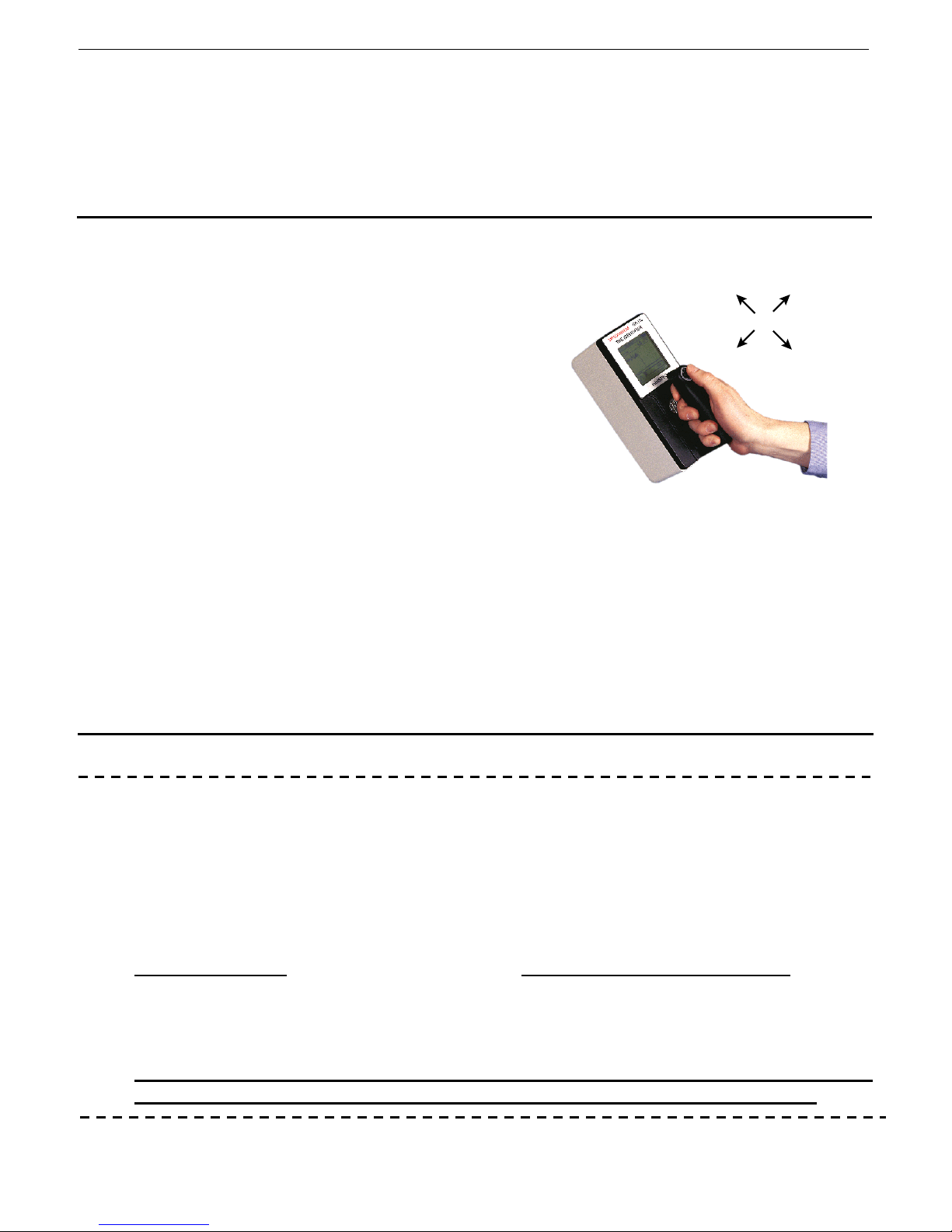
The unit is supplied with a single-button control device called THE JOYSTICK.
JOYSTICK ACTIONS
UP
(away
from you)
LEFT
RIGHT
DOWN
(towards you)
Page 12

SAIC Exploranium – GR-135 System Manual page: 12
4.0 QUICK START – MANUAL MODE
This section offers a VERY simplified guide to system operation; a more complete description is
available in Section 4+. The manual assumes that unit is being operated with the supplied
DOCKING-STATION (DS) – non-DS users please refer to Appendix C
a) CONNECT DOCKING STATION – connect the DS to an AC source using the cable supplied
b) REMOVE THE GR-135 BOOT – remove the attached Yellow protection boot
b) LOAD BATTERIES - remove rear door and insert 2 batteries – check polarity as marked - ONLY use
c) JOYSTICK OPERATION - the JOYSTICK moun ted on the handle (see pictur e above) is the only
d) POWER ON - a CL ICK DOWN for at least 2 seconds - the unit will power ON and after a few
e) DOCKING-STATION – place the unit in the DS to charge the batteries
f) STABILIZE – while in the DOCKING-STATION (which has an embedded 0.25uCi Cs137 stabilization
e) REMOVE from the DS and attach the Yellow boot for unit mechanical protection
f) SEARCH + DOSE - from the Main Menu, activate the SEARCH+DOSE mode by highlighting the
g) STOP – to stop any function – press ENTER until you see STOP on the display. Then ENTER again
h) IDENTIFY - Selecting IDENTIFY from the Main Menu begins a spectral reading for a pre-set
i) For a detailed explanation of these functions and other system functions - see the following Sections
the supplied rechargeable batteries. Replace battery clamp and door and ensure the door is correctly
seated.
control on the instrument. Basic JOYSTICK actions are UP, DOWN, LEFT, RIGHT. Some
operations require a short activation SHORT = less than 0.5secs – or LONG = more then 1
second. ENTER in the manual means LONG DOWN (more than 1 second) – see graphic in
Section 3 above
seconds the MAIN MENU is shown.
source) select STABILIZE then ENTER (LONG DOWN) and follow display prompts to automatically
set the system gain
item in the Main Menu and using ENTER (LONG DOWN) to select. The system display will show
the current count rate in counts/sec while the internal “audio meter” will give an audio response with
the tone related to radiation intensity. DOSE RATE data is also displayed
to go back to the Main Menu
duration. At the end of the sample period, a menu permits viewing the spectrum, peak analysis,
Nuclide Identification, storing the spectrum for later analysis or output of the spectrum to a PC.
Page 13
SAIC Exploranium – GR-135 System Manual page: 13
5.0 DETAILED OPERATION GUIDE
This section offers a detailed guide to system operation. The “AUTOMATIC” (= simplified) mode of
operation is described in Appendix A, note there is a special Users manual for “AUTOMATIC” only
operations.
The manual assumes that unit is being operated with the supplied DOCKING-STATION (DS) – non
DS users please refer to Appendix C for differences
5.1 JOYSTICK
The GR-135 is equipped with a rubber-covered
JOYSTICK on the instrument handle, referred to in
this manual as the JOYSTICK and this is the ONLY
control on the instrument. The great advantage of
UP
(away
from you)
this single button control is that besides being very
easy to use it also permits full operation EVEN
LEFT
WHEN WEARING GLOVES – a definite advantage in
many applications where protective clothing is
required. Various Joystick actions are permitted
depending on the application:
CLICK UP/DOWN - a SHORT (up to 0.5 sec)
push (CLICK) of the JOYSTICK UP (away
from the user) or DOWN (towards the
JOYSTICK ACTIONS
user) is used to scroll through the system
menus
ENTER - holding the JOYSTICK DOWN (toward the ON position on the joystick label) for about
ONE SECOND (in the manual referred to as ENTER) is used to activate the selection
highlighted on the display
CLICK LEFT/RIGHT – SHORT click used in some menus to change parameters and in the Main
Menu to adjust display contrast.
5.2 POWER
a) BATTERIES
The GR-135 has an integrated Battery-Charging capability and operates with the supplied two D-cell
rechargeable NiCd batteries for Docking-Station usage. The internal batter y charger permits the
battery charging system to be fully under software control. With the increased availability of
specialty batteries, this feature means that a wide variety of battery types can be used in the
instrument – the user simply selects battery type and the charger automatically selects the correct
charging parameters for this battery type. Consult Exploranium if special battery usage is required.
Alkaline batteries
damage and battery leakage may occur. An internal temperature sensor in the unit will shut power
down if an increased temperature is detected, to provide a high level of system protection but
system damage from battery leakage could still occur. See Appendix C for NON-DS operation.
When not in use for an extended period of time (1 month or more) – either leave
the unit charging in the DS – or remove the batteries to prevent leakage.
can be used but in this case DS operation is NOT permitted or system
RIGHT
DOWN
(towards you)
Page 14
SAIC Exploranium – GR-135 System Manual page: 14
b) LOADING BATTERIES
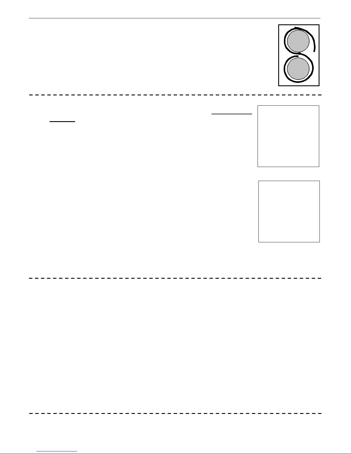
To load the batteries, remove the battery back door at the rear of the instrument
by applying a ¼ turn to the door latch. Insert the two rechargeable D-cell
batteries with the "+" to the small brass ring and the “-“ to the spring. The
fabric strip should be placed BEHIND the batteries to aid in their removal (see
fig). Ensure that both batteries are firmly seated, attach the plastic battery
retainer clip properly then re-attach the door. (Be sure that the door is properly
attached)
c) POWER ON
d) BACKLITE ON
To switch the unit on, CLICK DOWN (towards the user) for at least 2
seconds. The display will come on and show Fig. 1A for a few seconds.
The unit is carrying out internal testing to verify that the units’ components
are functioning correctly during this display.
TESTING
Fig. 1A
After approx. 3 seconds this display will be replaced by the normal startup
display shown in Fig. 1B and an audio beep will be heard.
If any errors are detected, they are displayed (see Appendix E). If n o
errors are found, the display will change to the start up screen (Fig. 4)
shown below after a few seconds
EXPLORANIUM
GR-135
The IDENTIFIER
VERSION 109
SER# 2001
MANUAL MODE ACTIVE
Fig. 1B
MANUAL MODE ACTIVE – shows that the unit is in the MANUAL mode that permits full unit
functionality
A BACKLITE option is built into the GR-135 such that the display may be viewed in low light
conditions. BACKLITE can be enabled in the system setup for frequent use or activated manually for
intermittent use. To enable the BACKLITE, be sure that the unit is OFF, then CLICK DOWN
(towards the user) and HOLD the JOYSTICK in this position. After about 3 seconds the display will
be illuminated (BACKLITE switches ON), after which the JOYSTICK may be released. The BACKLITE
will remain active until the unit is powered OFF. The GR-135 has a built-in battery saving feature
such that the BACKLITE will not turn ON if the battery voltage is below 2.2 V. This low voltage
indicates that there is little battery life left so disabling the BACKLITE feature allows the user to use
the remaining battery life optimally.
Note that to turn off the BACKLITE, the unit must be switched OFF then switched ON again with the
normal short click
The BACKLITE feature may be selected to be ON all the time for some applications or for set periods
of time as described in the SETUP section (Section 10) but users should be aware that enabling the
BACKLITE feature reduces battery life by an estimated 50%.
Page 15
SAIC Exploranium – GR-135 System Manual page: 15
e) POWER OFF - MANUAL
To power the unit OFF, CLICK UP (away from the user) and hold for
approx. 5 seconds. The display (Fig. 2) shows the seconds counting
down; 3, 2, 1. After this countdown the unit powers OFF. At any time
during the countdown, releasing the JOYSTICK will cancel the power
OFF.
LIKE ALL COMPUTER BASED SYSTEMS THERE IS A SLIGHT POSSIBILITY
THAT AN UNEXPECTED COMBINATION OF USER ACTIONS COULD CAUSE THE
WHILE HIGHLY UNLIKELY, USERS ARE ADVISED THAT IF UNUSUAL
ACTIONS OCCUR - SWITCH THE UNIT OFF AS DESCRIBED IN (e) ABOVE AND
f) LOW BATTERY WARNINGS
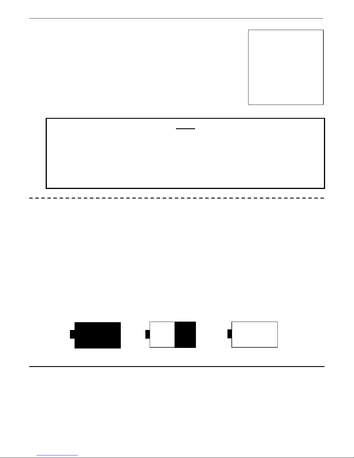
The Battery ICON at the top right of the display is used to provide the user with an idea of the
current battery status. Unfortunately rechargeable NiCd batteries exhibit a very flat discharge curve.
This means that for a very long period the battery voltage is almost constant and then it will
suddenly discharge very rapidly at the end of battery charge. This battery characteristic means that
it is not possible to display a fully accurate battery-life indication.
Exploranium recommends that it is a sensible precaution to carry a spare set of ALKALINE batteries
in the system pouch if extensive field operations are required, to act as a backup (but NOT for DS
operation!). This ensures that battery failure does not prevent data acquisition when required.
For convenience, most users tend to use the NiCd rechargeable batteries. To provide some level of
warning of imminent battery life - if the batteries fall below a certain level then a 3-beep audio
occurs and the Battery ICON changes to the message LOW. The user has between 2 and 10
minutes of measuring time left in the battery at this time. When there is no longer enough power to
allow measuring, the GR-135 turns off.
AT THE NEXT POWER ON THE SYSTEM SHOULD BE OK.
TURNING OFF
NOTE
SYSTEM TO HANG UP.
3 (2,1..)
Fig. 2
Full Charge ½ Charge Low Battery Warning
LOW
Fig. 3
5.3 SWITCHING FROM AUTOMATIC MODE TO MANUAL MODE
With the unit set up correctly and being operated by the user, it is important to ensure that no one
changes the system settings in an unauthorized manner. For this reason there is a “hidden” slider
switch in the battery compartment used to select modes. (On more recent models the slider switch
is located behind the battery door on the right hand side – see Figure on page 8).
The slider switch has 2 modes labeled “
the unit switched OFF, the user should select the m ode of operation then power the unit ON to
activate the mode.
A” for AUTOMATIC mode and “M” for MANUAL mode. With
Page 16

SAIC Exploranium – GR-135 System Manual page: 16
5.4 DISPLAY CONTRAST
When the unit is first turned ON, the user may use the joystick to adjust the Display Contrast to suit
themselves. Clicking LEFT changes contrast to lighter, clicking RIGHT changes contrast to darker.
The control is limited to 10 steps in either direction and when extremes are reach ed, an audio
double-beep is heard to advise the user that they are at the limit of adjustment. Note that the userset display contrast will be retained even when the unit is powered OFF.
Manual contrast adjustment is only enabled during the first 60 seconds
after power on. This is to prevent inadvertent contrast adjustment
during other system operations. 60 seconds is usually long enough for
adjusting contrast, however if further adjustment is required, switch
the unit off then on again to obtain another 60-second adjustment
After the initial contrast setting by the user, the contrast is automatically adjusted by
temperature compensation using an internal temperature sensor.
This is usually because they have set the CONTRAST
If a greenish-colored blank display is seen, switch the unit
OFF (UP for 5 seconds ensures the unit is switched OFF).
Now power ON, wait 5 seconds, then RIGHT click the
Joystick repeatedly. 5-6 clicks is usually enough to restore
the display CONTRAST – the display should now be visible.
If the display is blue, then repeat the above procedure but
click the Joystick LEFT.
Contact Exploranium if the display is still blank.
Some users switch the unit ON
USER ADVISORY
And see NO DISPLAY.
completely wrong.
NOTE
5.5 MAIN MENU
After the initial start-up screen, the GR-135 Main Menu appears.
The user may scroll through the menu items by a short click UP or
click DOWN. Reverse “highlighting” shows the current menu item
selected.
Menu items are selected by highlighting the desired item and using
ENTER to activate the selection.
MAIN MENU
SEARCH + DOSE
IDENTIFY
STABILIZE
DATA MEMORY
SETUP
MAINTENANCE
Fig. 4
Page 17

SAIC Exploranium – GR-135 System Manual page: 17
5.6 STABILIZATION
The GR-135 is designed to automatically carry out system stabilization in the AUTOMATIC mode in
the DOCKING STATION. Once this has been done correctly then internal temperature correction is
used to maintain this level even if the unit has not been stabilized for many hours.
However in the MANUAL mode the system must be stabilized manually using the functions
described in section 7.
If the unit decides that Stabilization is required then a STABILIZATION WARNING display will be
shown – see Fig. 5.
If DEFAULT PARAMETERS are loaded then this warning will be seen as Stabilization is required
before the SEARCH and IDENTIFY functions.
IT IS EXTREMELY IMPORTANT THAT
STABILIZATION BE CARRIED OUT IF REQUIRED
AFTER LOADING DEFAULT PARAMETERS - THE ACT
OF STABILIZATION SETS ALL THE SYSTEM
COMPUTATIONAL REQUIREMENTS FOR CARRYING
OUT THE IDENTIFY FUNCTION. WITHOUT THIS
STABILIZATION SERIOUS DATA ANALYSIS ERRORS
WILL OCCUR!
SEE THE FOLLOWING SECTIONS
FOR DETAILS ON OTHER FUNCTIONS
Fig. 5
5.7 EXTERNAL AUDIO
On the rear of the unit is a special connector as
shown in the rear view of the instrument shown in
the figure (external audio). Normally this
connecter is fitted with a sealing plug for weather
protection. However users with the optional
external earphone can plug it into this socket.
When this occurs the internal audio is silenced and
the audio tones are only audible through the
external earphone.
This silencing of the units audio is especially useful
in covert audio scanning or when the operator
does not wish to alarm anyone with sudden audio
tone increases
EXTERNAL
AUDIO
Page 18
SAIC Exploranium – GR-135 System Manual page: 18
6.0 SEARCH+DOSE
6.1 SEARCH MODE
TOTAL
RATE
NAI
DOSE
SEARCH
1234
MEAS
VS 2K
1.3mR/h
125uR/h
WARNING!!
HI RADIATION
DOSE RATE
MOVE AWAY!!
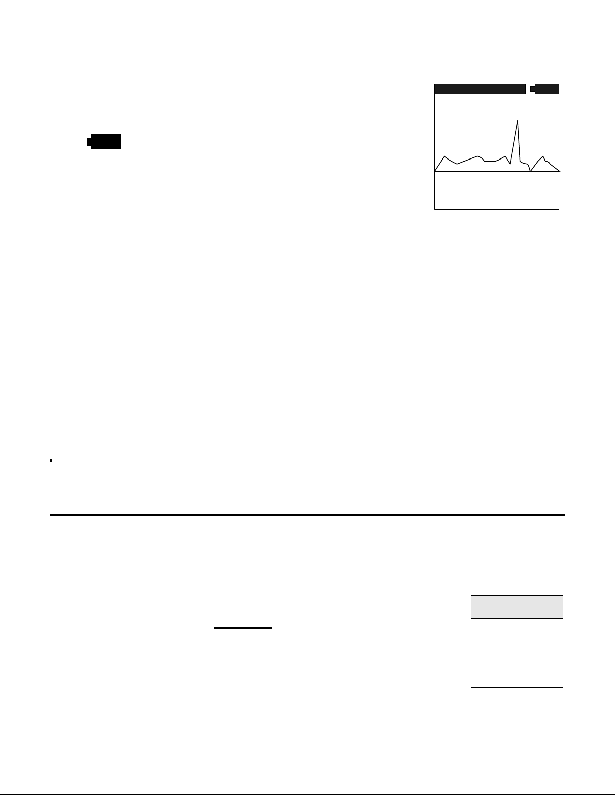
Select this menu item then ENTER to activate – fig. 6 is seen
SEARCH - Shows that the system is in the SEARCH mode.
- The Battery Icon shows battery status.
TOTAL - Shows that the SEARCH mode is using the full Total
Count data. See Section 9.1 for use with special ROI
data.
1234 - Is the current count rate in counts per second (cps)
updated every sample period. Fig. 6
MEAS - means unit is measuring (STOP means it is not measuring)
VS 2K - This is the vertical scale of the “chart-recorder” (in this case 2000cps). Most users let
the unit auto-scale but the user can manually set a fixed scale in SETUP – section 9.1
CHART RECORDER - The data in the data box shows the last 126 samples of data in a “chart-
recorder” format (left to right with the most current data on the LEFT). Therefore, at
a one second data rate, 126 seconds of data are displayed OR at a five second data
rate, 630 seconds of data are displayed etc. The Chart Recorder display is updated at
the end of every sample period.
D.RATE - is the current DOSE RATE in selected units – see Section 9.4 for more details
DOSE - is the TOTAL DOSE accumulated from the point in time SEARCH+DOS E mode was
activated – see Section 9.4 for more details
STOP – to stop this function press ENTER and the display will go back to the Main Menu. If the
user presses AND HOLDS the joystick in the ENTER position, the display will stop updating
and permit the user to inspect the data. Releasing the joystick goes back to the menu.
6.2 HIGH DOSE
The system has a preset maximum Dose Rate level – normally set at 2000uR/h. Below this level
Dose Rates are considered acceptable for system operation. However above this level it is
recommended that users move away from the source of radiation to reduce this Dose Rate level
to an acceptable level. To make things simple, the GR-135 advises the users automatically if the
Dose Rate level goes above the preset limit.
If this level is exceeded a distinctive
display changes (fig 7) :
As noted, the user should back away until the Dose Rate level falls below
this limit and the display warning goes away.
Users should be reminded that short-term operation close to the limit has Fig. 7
a negligible hazard level but prolonged operation significantly above this level is not
recommended
audio warning tone occurs and the
Page 19

SAIC Exploranium – GR-135 System Manual page: 19
6.3 NEUTRON ALARM
The system has a selectable Neutron Alarm Threshold (for settings see
Section 10.3). If this level is exceeded a distinctive audio warning tone
occurs and the display changes (fig 8).
This display will stay on the screen as long as the Neutron data is above the
threshold and for 5 seconds after the data drops below the alarm
threshold to ensure that the user can inspect the data adequately.
Fig. 8
WARNING
NEUTRONS
DETECTED
6.4 SEARCH ALARM
If the ALARM LEVEL parameter (section 10.1) is set to a preset value and
the radiation field exceeds this value, a distinct audio beep will be heard and a
pop-up box will appear as shown in the figure. As the user moves away from
the source the audio and pop-up display will go away.
WARNING!!
ALARM
ABOVE
LIMIT
Fig. 9
6.5 SEARCH - AUDIO
In the SEARCH mode the radiation data from the high-sensitivity Sodium-Iodide (NaI) detector is
used to create an audio search capability thus permitting the user to have an “eyes-free”
operational mode. It is very difficult to scan a vehicle and inspect the display continuously.
The GR-135 scans the incoming data at a 20 TIMES a SECOND RATE – and converts the
radiation field into a mode that changes the frequency of the audio tone to reflect the radiation
field intensity. Various parameters are used (see section 10 for details) to adjust system
performance to suit the user. In the majority of cases the audio gives occasional “beeps” of low
intensity audio on normal background (this shows the user that the audio system is alive) but in
the presence of a real radioactive field the audio frequency changes rapidly. With this feature it
is very easy to scan back and forwards to readily locate the highest audio pitch which is the
maximum radiation intensity.
6.6 SEARCH MODE - DATA RECORDING
The data displayed during the SEARCH mode can be recorded in memory. Recording to memory is
implemented by menu selection in the SETUP - SEARCH menu (Section 9.1). When the “OUTPUT
TO” parameter is set to “MEM” and the SEARCH mode is started, the data is logged into memory at
the selected Sample Rate. The message SEARCH->MEM will be displayed at the top of the screen
during the SEARCH to indicate that the data is being saved to memory.
Data recording is terminated when the memory is full or the mode is stopped (ENTER). Every time
the SEARCH mode is stopped then started again, a new header is written so the data can be
retrieved later with the appropriate time information. Remember that all SEARCH data will be loaded
into memory until the data recording option is disabled in SETUP mode.
The data memory can record approximately 45,000 readings at the selected data rate. Thus, at a
one sample per second data rate, the memory will hold almost 12.5 hours of SEARCH+DOSE data.
Once the GR-135 memory is full the message MF (memory full) will be displayed at the top of the
screen and the user gets a 3-beep audio warning and the SEARCH>MEM label is removed.
Page 20

SAIC Exploranium – GR-135 System Manual page: 20
The user should be aware that at the beginning of each new SEARCH mode activation, a header is
stored in memory. This header uses memory space equivalent to 6 SEARCH samples. Therefore, if a
large number of separate SEARCH samples are stored in memory, slightly less memory is available
for samples than if the SEARCH was taken in one complete set.
When the internal DATA MEMORY is full as described above, users should return to MAIN MENU
(ENTER) and dump the data to an external PC as detailed in Appendix B
To log data directly to a PC refer to Appendix B
Page 21
SAIC Exploranium – GR-135 System Manual page: 21
7.0 IDENTIFY
This mode enables detailed spectral analysis and permits spectrum display, peak identification and
nuclide identification. The user should observe some simple operating procedures to get best results
from the instrument. Exploranium recommends the following procedure:
- Search and locate a source of radiation in the SEARCH mode as this has maximum
sensitivity
- If a source of radiation is found then use the SEARCH mode to estimate its approx.
geographic boundaries (by observing the count-rate or audio)
- Position the detector facing the approximate center of the area of radiation
- Move the unit away (or toward) the source (in the SEARCH mode) until the count rate is
between 2000 and 5000 counts/sec for best results
- Highlight IDENTIFY in the Main Menu and press ENTER to select.
- The GR-135 immediately begins to acquire a spectrum with the display appearing as shown
in Figure 10. Note the system DEAD-TIME – for best results this should be between 10-
25%
- At the termination of the sample the data will be analyzed for radioactive material and the
display will show the results
- See below for full details
NOTE – Section 7.1 covers instrument behavior if IDENTIFY is started from the MAIN MENU.
Section 7.2 – 7.8 cover a different mode of operation
7.1 IDENTIFY DISPLAY
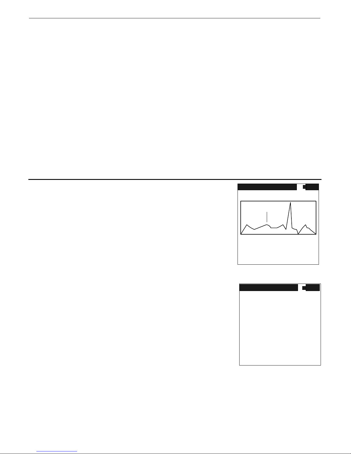
As the sample progresses the display is updated at a 1/sec rate as
shown in Fig. 10 until the preset sample time is reached. For full
details of this display see section 7.4 below.
DETECTOR NAI
D.TIME 30% NEUT 0 CTS
CURSOR 1812 KEV 1234 CTS
ROI# 1 1200 CTS
TIME 42 S SET 60 S
Fig. 10
ANALYSIS DISPLAY
When the sample terminates the Nuclide Identificati on function is
automatically activated. The display shows “COMPUTING –
PLEASE WAIT” for a few seconds then Fig. 11 is displayed.
This display shows any Nuclides that have been identified in 3
columns:
TYPE – the Nuclides in the library are divided into 4 categories
INDustrial, SNM (Special Nuclear Materials), MEDical and
NOR(M). See Appendix D for a list of isotopes and types.
ISOTOPE – the full name of the isotope (see App. D)
Fig. 11
SIZE – the relative size of the peaks of the isotope in SD units.
(Standard Deviation units – this gives a good idea of the significance of the peak)
For isotopes with multiple peaks the individual peaks SDs are summed.
NOTE: This relatively simplified display is intended to offer quick user analysis capability. For more expert
users see the further functions below.
ENTER – pressing ENTER goes to the ANALYSIS menu for further functions
IDENTIFY
sp 1
range 0 - 3072keV
67
MEAS
VS 2K
NUCLIDE IDENT
TYPE ISOTOPE SIZE
I ND Cesium-137 11
ENTER TO CONTINUE
Page 22
SAIC Exploranium – GR-135 System Manual page: 22
7.2 ANALYSIS MENU
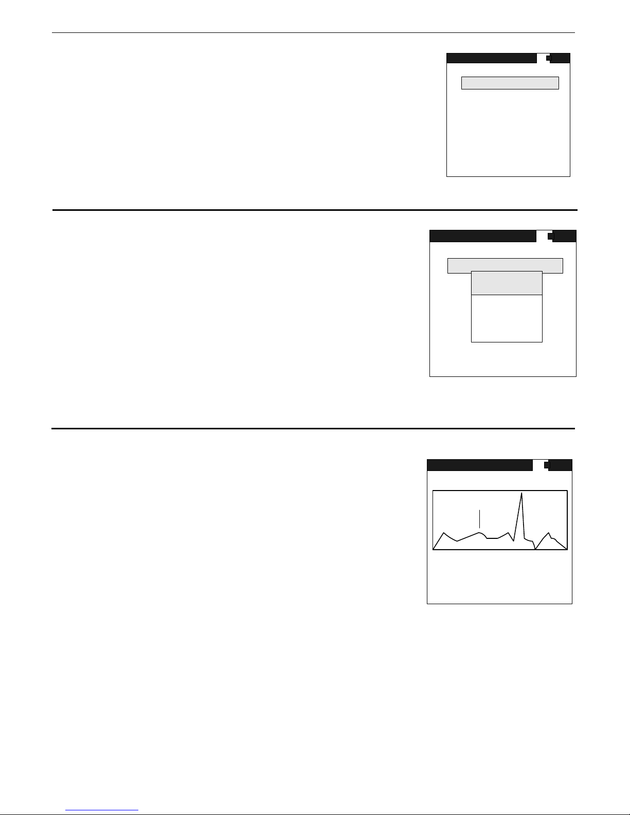
When Nuclide ID is complete, ENTER goes to the main ANALYSIS menu
(Fig. 12) where further functions can be selected
ANALYSIS
STORE SPECTRUM
START MEAS.
SEE SPECTRUM
PEAK ANALYSIS
NUCLIDE IDENT.
OUTPUT SPECTRUM
MAIN MENU
Fig. 12
7.3 STORE SPECTRUM
This option stores the current (most recently measured) spectrum in
the memory of the GR-135, assigns it a unique Sample Number and
tags it with the date and time of measurement for easy
identification. All data recorded in memory can be downloaded to
an external computer.
To store data in memory, highlight STORE SPECTRUM and
ENTER. A new display appears for 10 seconds as shown in fig.
13 – in this case showing that this spectrum has been stored as
Spectrum #12.
Note that the GR-135 can store up to 187 complete 1024 channel spectra in memory.
ANALYSIS
STORE SPECTRUM
START MEAS.
MESSAGE
SEE SPECTRUM
SPECTRUM
PEAK ANALYSIS
NUCLIDE IDENT.
#12
STORED
OUTPUT SPECTRUM
MAIN MENU
Fig. 13
7.4 START MEAS
This option allows the user to take another spectrum sample
without having to go back to the Main Menu and selecting
IDENTIFY again. If this option is selected then the IDENTIFY
sampling display (shown in 7.1 above) is shown and data
accumulation begins again. As the sample progresses the display
is updated at a 1/sec rate as shown in Fig. 14 until the preset
sample time is reached.
NOTE: If the IDENTIFY analysis capability is started from the
START MEASUREMENT menu item then at the end of the sample
the display goes to the ANALYSIS menu so the user can select
DETECTOR NAI
D.TIME 30% NEUT 0 CTS
CURSOR 1812 KEV 1234 CTS
ROI# 1 1200 CTS
TIME 42 S SET 60 S
subsequent actions. However if IDENTIFY is started from the Fig. 14
MAIN MENU it automatically carries out NUCLIDE ID to try to somewhat
simplify user actions.
Labels are:
Sp1 – the last spectrum # that was stored. So if the current sample (when complete) is stored – it
would be Spectrum #2
RANGE 0-3072keV shows that the full 3MeV spectrum is displayed
MEAS – means that the system is in measurement mode
IDENTIFY
sp 1
range 0 - 3072keV
67
MEAS
VS 2K
Page 23
SAIC Exploranium – GR-135 System Manual page: 23
VS 2K – means that the vertical scale is currently 2K (2000cps). This is automatically changed if
any channel exceeds this limit.
DETECTOR – NaI shows that the Sodium-Iodide detector is currently in use
D.TIME – shows the Sodium-Iodide dead time as a %
NEUT – The count rate for the Neutron detector in cts/sec
CURSOR – KEV - CTS – the cursor position data in Channels and Counts
ROI# - CTS – the ROI# and counts in the ROI in counts
TIME – shows sample progress (42 secs currently)
SET – shows the preset sample time of 60 seconds.
The sample accumulates until the preset sample time is reached but the user can stop the sample at
any time by pressing ENTER. When the sample is complete it automatically activates the Nuclide ID
mode and the display results as shown in Fig. 11 are seen.
7.4.1 DATA OVERFLOW
The maximum count possible in any channel is 65535 during a sample. If any channel exceeds this
level the channel data is flagged and “frozen” but the sample time continues until it is complete.
This way the high count rates of lower energy nuclides do not inhibit the analysis of higher energy
peaks
7.5 SEE SPECTRUM
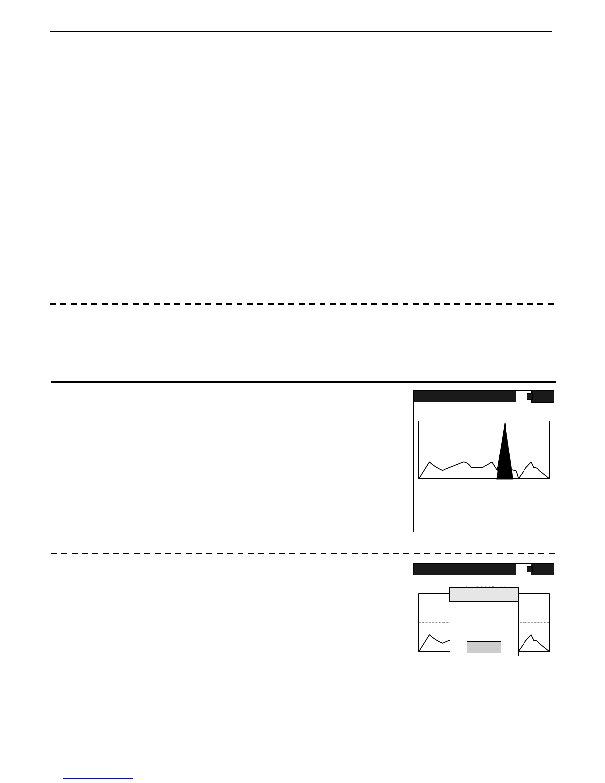
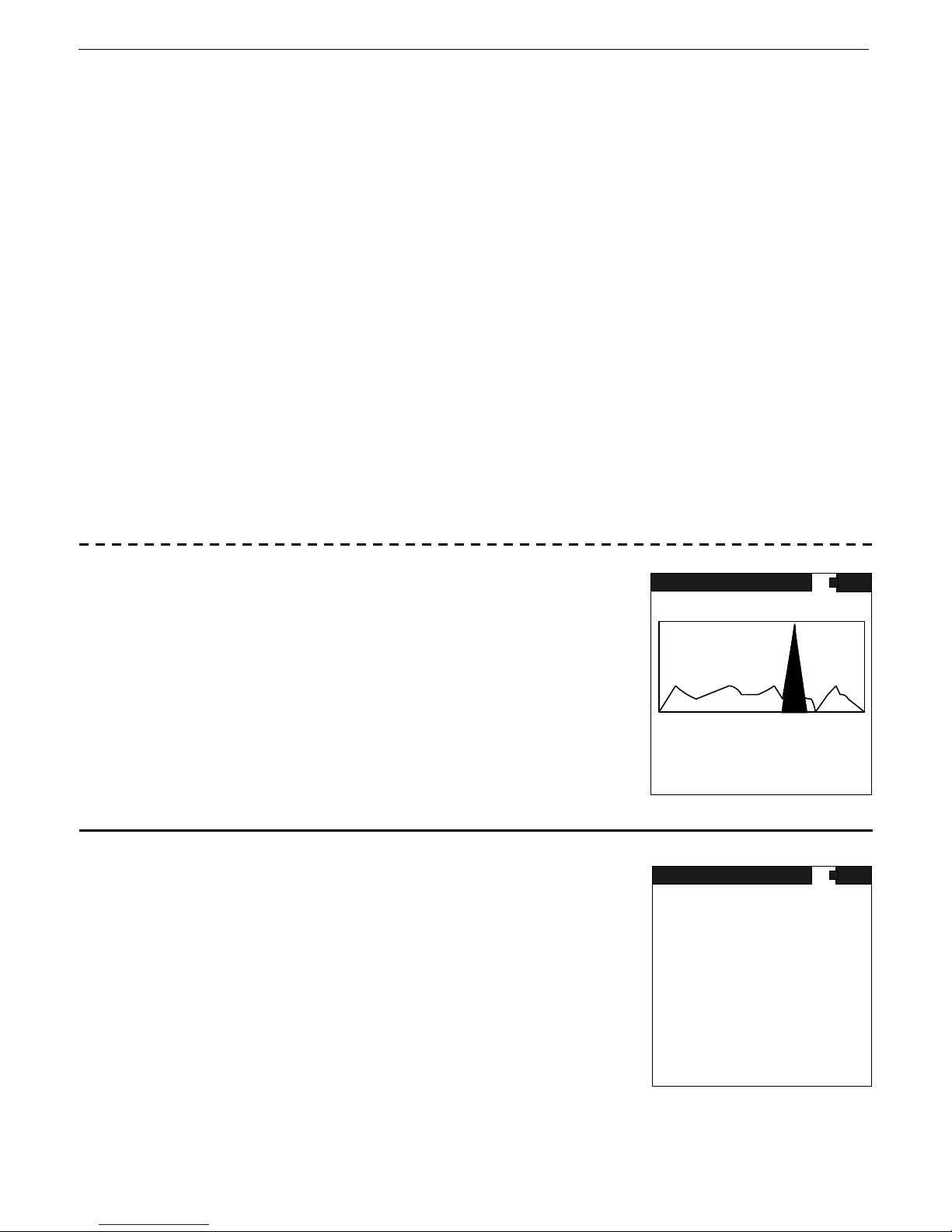
This display shows the spectrum of the last sample analyzed. The
figure shows a typical display. Data are defined as described in 6.4
RANGE 470 - 854 keV
ANALYSIS
STOP
VS 2K
above. The only difference is:
TIME/SET - show the sample preset time period – the fact they
are the same means the sample terminated at it’s full count
(in this case no premature termination due to overflow)
DETECTOR NAI
PEAK 662 KEV 220 CH:
CURSOR 1025 KEV 65535 CTS
ROI NO 0 1234567 CTS
TIME 30 S SET 30 S
Fig. 15
7.5.1 SEE SPECTRUM
The display is only 128 pixels (dots) wide and the GR-135 utilizes a
1024 channel spectrometer. Thus if the full spectrum is displayed,
each pixel shows the average of 8 actual data channels. In many
cases the user wants to inspect the spectrum in greater detail so a
zoom feature is available. To activate this featu re press ENTER and
a new display appears (Fig. 16):
The cursor goes immediately to the ZOOM RETURN selection and
if ENTER is pressed again it goes back to the ANALYSIS menu
DEAD-TIME:30% DET:NAI
CURSOR 1812KEV 1234CTS
ROI#: 1 1200CTS
TIME: 60 S SET: 60 S
IDENTIFY
sp 1
range 0 - 3000keV
NEXT
ZOOM 8x
ZOOM 4x
ZOOM 2x
67
ZOOM 1x
RETURN
MEAS
VS 2K
The other selections permit the zoom feature:
X8 – this is the maximum zoom selection and sets the display to show 1 pixel = 1 channel. This
means that the full display now covers 128 channels = 384keV
Page 24
SAIC Exploranium – GR-135 System Manual page: 24
X4 - this selection sets the display to show 1 pixel = 2 channels. This means that the full displ ay
now covers 128 channels = 768keV
X2 - this selection sets the display to show 1 pixel = 4 channels. This means that the full displ ay
now covers 128 channels = 1536keV
Fig. 16
X1 - this selection sets the display to show 1 pixel = 8 channels. This means that the full displ ay
now covers 128 channels = 3072keV
RETURN – goes to the Analysis Menu
Correct operation of the ZOOM feature is t o cursor al ong the display and position the cursor on a
peak of interest, then activate the zoom feature. Once the zoom selection is made the display is
centralized on the peak. As an example:
- the user positions the cursor on the 662keV Cesium peak
- then they select the x8 zoom and press ENTER
- the display now displays only the selected peak at the center of the display and the display
covers only a 384keV range.
Thus the limits of the display are shown as 470-854keV and this range is shown on the display
If the user moves the cursor the cursor stays at the center of the display and the spectrum scrolls
past it until the limits of the display are reached.
PEAK DISPLAY -
In the SEE SPECTRUM mode as the cursor moves ac ross the display ,
any peaks that have been identified in the analysis routine are
highlighted and if the cursor enters this highlighting area the display
RANGE 470 - 854 keV
ANALYSIS
STOP
VS 2K
shows the peak information on the display as KEV and CH# - as
shown in Fig. 17
If the cursor is moved to the next peak, the first peak will continue
to be displayed until the next peak is entered in which case the
PEAK display shows the new peaks data.
DETECTOR NAI
PEAK 662 KEV 220 CH:
CURSOR 1025 KEV 65535 CTS
ROI NO 0 1234567 CTS
TIME 30 S SET 30 S
Fig. 17
7.6 PEAK ANALYSIS
Selecting the PEAK ANALYSIS mode results in an automatic analysis
of the last recorded spectrum to identify peaks. The results are
displayed in ascending order, sorted by energy level. Data labels:
Peak - two data are shown, the peak position in keV
(77) and channels (29)
FWHM - Full Width Half Maximum - The computed FWHM of the
located peaks in % gives an idea of the quality of the peak.
SIZE - The amplitude of the peak in SD units
Fig. 18
PEAK ANALYSIS
PEAK FWHM SIZE
77 29 34.1 4
197 69 10.9 4
665 221 6.7 17
PRESS ENTER TO CONTINUE
Page 25

SAIC Exploranium – GR-135 System Manual page: 25
“-more-“ - The word “-more-“ is displayed at the bottom of the screen when more peaks have
been identified than can be displayed on one screen. A short CLICK DOWN will show the
next screen with a continued display of computed peaks. If “more” is not shown, then all
identified peaks are displayed and ENTER returns you to the ANALYSIS menu.
ENTER to go back to the Identify menu
7.7 NUCLIDE IDENT
If this mode is activated then a new Nuclide Identification analysis of
the selected spectrum is carried out. The display shows
“ANALYZING SPECTRUM PLEASE WAIT” for a few seconds
then the display shows the NUCLIDE LIST screen – Fig. 19. Note
that this display is a more complex version of the previous Nuclide
ID display shown in Fig. 11 as this secondary display is intended to
show a higher level of details for further user analysis.
Cs-137 – is the isotope label of the identified isotope
21 - this is the relative amplitude of the isotope in Standard-
Deviation units. In the case of an isotope with multiple Fig. 19
peaks this is the sum of all the relevant peaks.
Non Identified – this shows the sum of all the peaks that cannot be identified. Usua lly these peak s
are very small so they are suppressed in the simplified analysis screen as for most users they
are confusing, however for specialized users they may be of interest. Note in the AUTO
display, any peaks that are statistically unimportant are suppressed
HIGHLIGHTING – when the display appears, the first isotope is highlighted. The joystick can be
used to move up/down the displayed list to highlight a required item
RETURN – pressing ENTER goes to the main Identify menu
7.7.1 NUCLIDE DETAILS
When the highlighted isotope is selected by cursor, then ENTER
pressed, the details of that isotope selection are displayed – Fig. 20.
This display shows all the peaks related to the isotope and various
data about them:
Cs-137 – is the isotope identified then selected
1/1 – relates to the isotope identification requirements in this case
a single peak is required for identification
662 – the peak in keV
Fig. 20
6.6 – the FWHM of the peak, a useful measure of peak quality
15 – the amplitude of the peak in SD units
ENTER returns to the IDENTIFY screen
NUCLIDE LIST
Cs-137 21
Non Identified 4
RETURN
NUCLIDE DETAILS
Cs-137 1/1
662 6.6 15
30 30.0 11
ENTER TO CONTINUE
Page 26
SAIC Exploranium – GR-135 System Manual page: 26
7.7.2 NEUTRONS
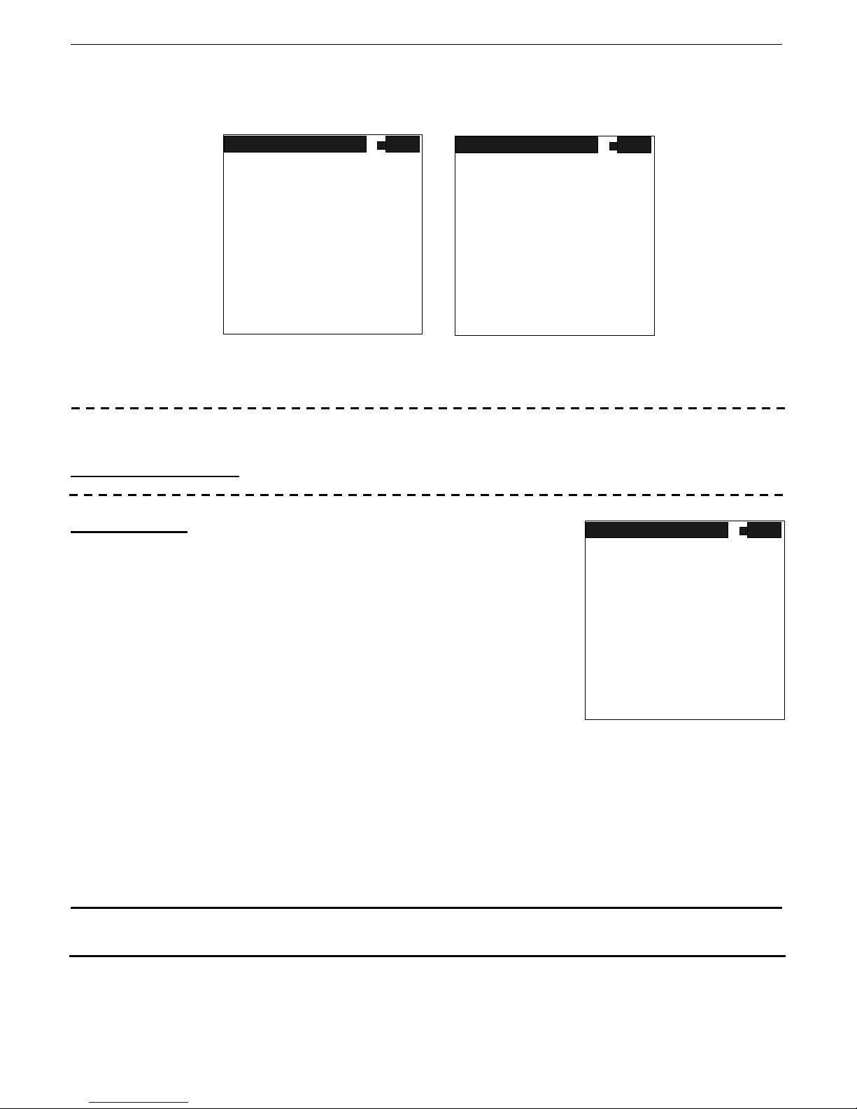
If the integrated NEUTRON sensor detects the presence of Neutrons, this data is displayed as pseudo
Dose data (calibrated for Cf-252) as shown in Fig. 21 and 22 (or as COUNTS depending on
parameter settings in SETUP)
NUCLIDE IDENT
TYPE ISOTOPE SIZE
I ND Cesium-137 11
NEUTRONS 0.452uSv/h
NUCLIDE LIST
Cs-137 21
NEUTRONS 0.452uSv/h
RETURN
ENTER TO CONTINUE
Fig. 21 Fig. 22
In SETUP (section 10) special parameters are used to optimize Neutron performance.
7.7.3 OTHER DISPLAY LABELS
NO NUCLIDES FOUND
– this means that the analysis routines found no identifiable nuclides
CZT REQUIRED
– this means that the analysis showed some uncertainty
NUCLIDE IDENT
about the peaks so a CZT analysis is required. In the AUTOMATIC
mode this is fully automatic, however in the MANUAL mode the
user must use SETUP/IDENTIFY/DETECTOR and set
DETECTOR=CZT then carry out data analysis
TYPE ISOTOPE
CZT Required
I ND Thorium-232
In this case the Sodium-Iodide spectral analysis and the CZT
spectral analysis are totally separate
ENTER TO CONTINUE
Fig. 23
NOTE: USERS ARE ADVISED THAT IN THE MANUAL MODE THE SODIUM-IODIDE DATA
ANALYSIS RESULTS ARE SEPARATE FROM THE CZT ANALYSIS RESULTS. SO IT IS
NECESSARY TO NOTE THE RESULTS FROM THE NaI BEFORE SWITCHING TO THE CZT (as
long as the spectra are all stored – use STORE SPECTRUM – then the users can go back
and look at all spectra when they want)
MAIN MENU Exits back to the Main Menu
Page 27

SAIC Exploranium – GR-135 System Manual page: 27
8.0 STABILIZE
8.1 STABILIZATION - GENERAL
When any spectrometer is turned ON, the internal electronic components exhibit some level of warmup drift with time, which may be exacerbated by chang es in the ambient temperature. SodiumIodide crystals typically exhibit a +/-15% change over the -10 to +50
uncorrected, this drift could seriously affect data analysis. For this reason, the GR-135 incorporates a
procedure called STABILIZATION to remove these effects. Stabilization automatically “fine-tunes”
the system to adjust the internal system gain and align the spectrometer correctly.
The GR-135 carries out Stabilization in various ways.
a) AUTO-STABILIZATION in the DOCKING STATION – AUTOMATIC
b) MANUAL-STABILIZATION in the DOCKING STATION – see section 8.3
c) AUTOMATIC CORRECTION when in USE – see section 8.4
e) MANUAL-STABILIZATION with no DOCKING STATIO N – at any time the user can activa te
STABILIZE from the Main menu and then use an external Cesium source to carry out the Stabilization
function
8.2 AUTO-STABILIZATION IN THE DOCKING STATION – AUTOMATIC MODE
If the GR-135 unit is set in the AUTOMATIC mode and placed in the DS, the system starts
automatically stabilizing on the very small (0.25u Ci) Cesium source embedded in the DS. The display
shows system activity and advises the user when stabilization is complete. During the entire time
the unit spends in the DS, the batteries are continually charged and the system is continually
stabilized. See full details in Appendix A
8.3 MANUAL-STABILIZATION IN THE DOCKING STATION
For normal operation the Docking Station is used (refer to Appendix C
for non-DS operation). From the MAIN MENU select “STABILIZE”
and press ENTER the display shows Fig. 23
This function is usually used with an external source, hence the
display wording. The user can assume that the source in the DS is
positioned correctly - so press ENTER to continue. (Selecting UP
returns to the Main Menu).
Fig. 23
Stabilization will now occur, the system is fully automatic, various
displays will be seen (the word “COMPUTING” may appear as well
as some data are being processed), then finally a beep shows that
the process is complete with the display as shown as in Fig. 24
These data are:
PEAK - this is the peak channel of the centroid of the
accumulated spectrum. The correct final channel for
CESIUM stabilization is channel 220 (+/- 0.5ch).
Fig. 24
o
C temperature range. If
MODE – see section 8.2
STABILIZE
PLACE CS SOURCE
AT THE FACE
OF THE GR-135
PRESS ENTER
TO CONTINUE
OR UP TO EXIT
STABILIZE
STABILIZATION
COMPLETED
REMOVE CS SOURCE AND
PUSH ENTER TO CONTINUE
PEAK: 220.1
FWHM: 6.8%
OLD GAIN : 522
NEW GAIN : 514
Page 28

SAIC Exploranium – GR-135 System Manual page: 28
FWHM - the Full-Width-Half-Maximum is a measurement of the quality of the detector to
resolve narrow peaks. The best detectors when new have a FWHM of 6 – 6.5%
but good operation is possible up to 8.5%. Above 8.5% the spectral peaks are
widening, making accurate peak analysis very difficult, and above 9.5%
spectral analysis, especially in the lower energy area, is almost impossible.
NEW GAIN - the Gain computed based on the error of the peak centroid calculation
OLD GAIN – the gain setting before the gain is corrected
System stabilization is now complete so the unit may be removed from the Docking-Station and
used. However if the user is not ready then the GR-135 may be left in the DS to keep the
batteries charged. This process also keeps the unit “warmed-up” as well as continuously
charging the batteries so when not in use it is recommended that the unit remains in the DS.
NOTE: In this software release – automatic stabilization in the DS in the MANUAL mode is NOT
supported
8.4 AUTOMATIC CORRECTION WHEN IN USE
When the unit is removed from the Docking-Station, the GR-135 electronics detects this change.
Stabilization on Cesium is automatically halted and the current detector temperature noted. As the
detector temperature changes, the system automatically corrects for any gain drifts using a built in
gain-correction Vs temperature curve so the Gain is maintained correctly.
Page 29

SAIC Exploranium – GR-135 System Manual page: 29
9.0 DATA MEMORY
If this is selected a new menu appears :
Fig. 25
9.1 STATUS
Selecting STATUS shows the current state of the data memory. The
GR-135 can store data from the 2 operational modes
(SEARCH+DOSE and IDENTIFY) in different formats. Each set of
data is tagged with a special header that identifies the type of data.
The SEARCH+DOSE data are classified as SAMPLES and IDENTIFY
data are classified as SPECTRA.
STORED - This indicates the current status of data storage.
9.1.1 MEMORY SPACE
SPACE AVAILABLE - This indicates available space for additional sample or spectral data.
The SEARCH+DOSE data are stored in a fixed data forma. For all data storage, the header is
written to memory first and then each data sample is recorded separately.
The header is 47 bytes in size and each sample is 8 bytes. Thus, a 10 sample record contains,
Header 47 bytes
10xSample (8) 80 bytes
Checksum 1 byte
TOTAL 128 bytes
Therefore, the amount of memory space occupied by data is a function of how many samples ar e
recorded. The system automatically computes available space based on this information but
considers the presence of only one set of header information and the rest being dat a. If the user
takes separate sets of readings (i.e. more than one header) the number of samples required to fill
the data memory will be less than that calculated by the GR-135 due to the memory requirement for
the extra headers. Therefore, the available memory display data should be used only as a guide.
The IDENTIFY mode records data in a much larger format as each reading is a 1024 channel
spectrum with 2 bytes/channel stored as follows:
Header 47 bytes
1 spectrum 2048 bytes
Checksum 1 byte
TOTAL 2096 bytes
DATA MEMORY
STATUS
DUMP
ERASE
MEM SCAN
MAIN MENU
STATUS
STORED
SAMPLES 0
SPECTRA 0
SPACE AVAILABLE
SAMPLES 39313
SPECTRA 187
ENTER TO CONTINUE
Fig. 26
Page 30
SAIC Exploranium – GR-135 System Manual page: 30
9.2 DUMP
DUMP is a utility for outputting data stored in the GR135 memory to an external utility program
such as the Exploranium supplied PC utility program IdentiView (described in Appendix B). .
Selecting DUMP allows the user to transfer stored Survey, Dose and Spectral data to an external
PC via the data transfer cable from the DS unit. It is critical that the GR-135 be turned OFF
before connecting the unit to the data transfer cable. If the unit remains ON, any shock or
power surge arising from the connection may corrupt data in memory.
User may use such utilities as HyperTerminal to output the stored data however the majority of
the stored data is in a Binary format so the user must have special conversion utilities to convert
the data in the format they require.
Note the RS232 port is configured as :
- Baud = 19200
- Data bits = 8
- Parity = none
- Stop bit = 1
- Flow control = none
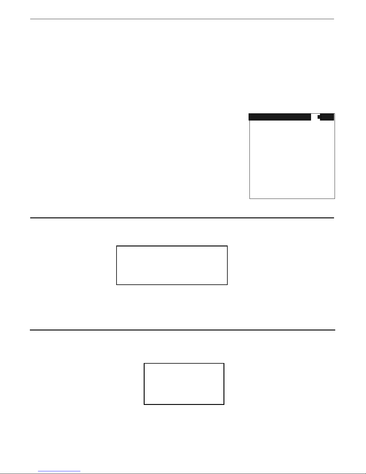
Selecting DUMP will produce the display shown in fig. 27. When
the appropriate PC software is operating, data may be transferred
by CLICK DOWN. Pushing the button up will cancel
this function. When data transfer is complete Fig. 27
DATA MEMORY
TO DUMP MEMORY
PUSH BUTTON DOWN
OR UP TO QUIT
9.3 ERASE
Selecting this function produces a new display. The display shows:
Pressing the button down three times erases the data memory completely. The first two times the
button is pressed, the word CLEAR should appear at the bottom of the display.
Users Are Warned That Erased Data Cannot Be Recovered!
PUSH ENTER THREE TIMES
TO ERASE MEMORY
OR ONCE UP
TO QUIT
9.4 MEM SCAN
This selection lets the user inspect and re-analyze spectra previously stored in memory.
If this option is selected, the first spectrum in memory summary is displayed. For example:
Note the DATE is in YY – MM – DD format
The user must CLICK LEFT/RIGHT to select the required spectrum. The spectrum number is the
same one used as a label during the spectrum store. The Date/Time of the recorded spectra are also
provided for reference.
SPECTRUM #1
DATE 02 01 18
TIME 12 36 50
Page 31
SAIC Exploranium – GR-135 System Manual page: 31
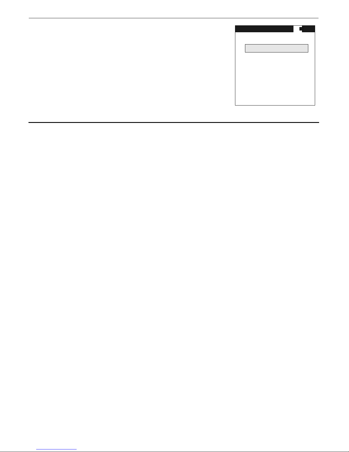
Once a spectrum is selected then ENTER activates this feature
and the selected spectrum is selected and the MEM SCAN menu
REANALYSIS
is shown. The user may select PEAK ANALYSIS etc. as required
The features and displayed data are exactly the same as in the
IDENTIFY features described in sections 6.4 etc.
MEM SCAN
START MEAS.
SEE SPECTRUM
PEAK ANALYSIS
NUCLIDE IDENT.
MAIN MENU
Fig. 28
Page 32
SAIC Exploranium – GR-135 System Manual page: 32
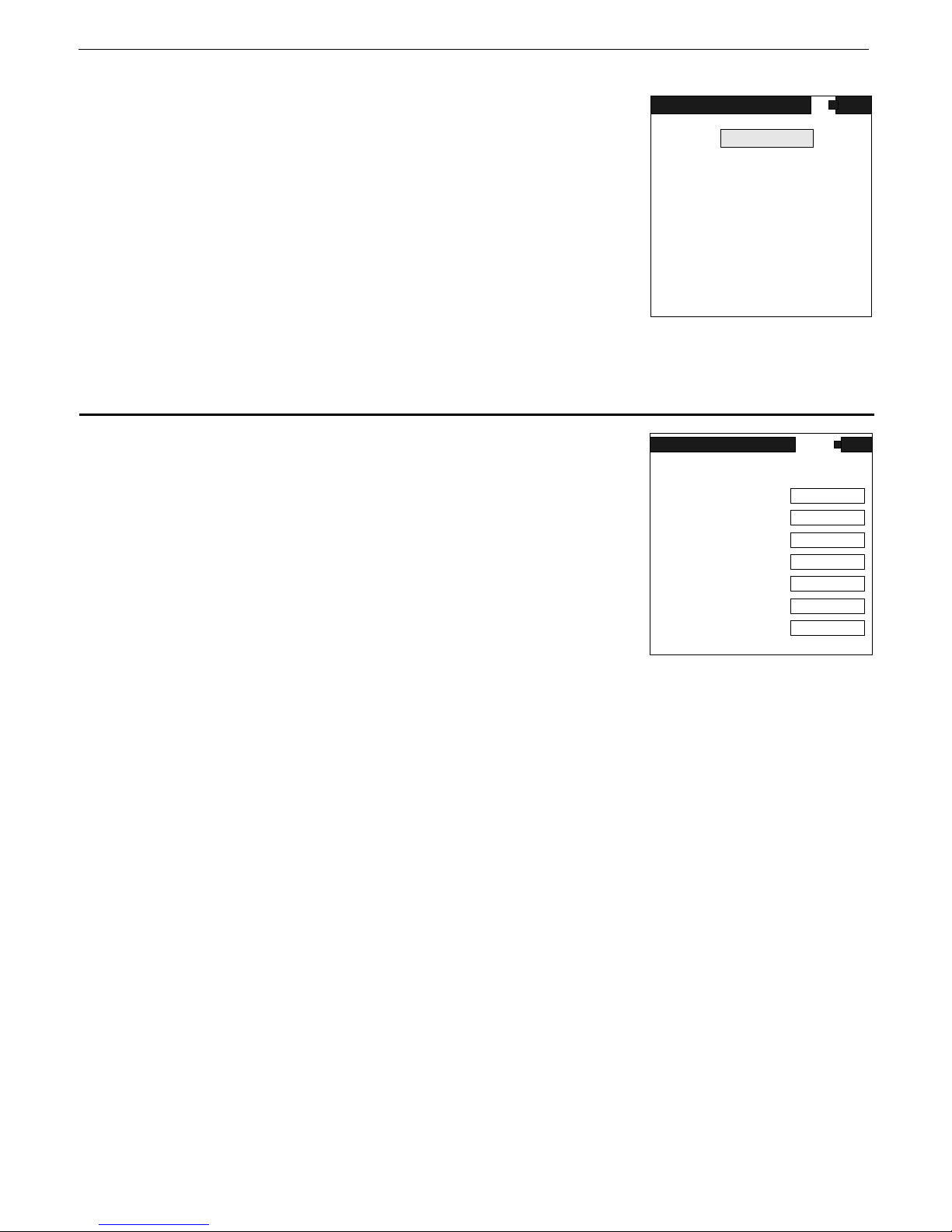
10.0 SETUP
These menus permit the user to setup the required operating
parameters. If this item is selected from the MAIN MENU this
display is seen.
Use the cursor UP/DOWN to select (highlight) the required
selection then ENTER to activate this selection.
Inside each menu use UP/DOWN cursor action to select a
parameter then LEFT/RIGHT cursor action to change the item.
ENTER to exit and accept the changes
Fig. 29
For all the selections below, the normal default selection is shown in large bold print
10.1 SEARCH
Selections are:
a) OUTPUT TO - Options -
OFF - the data is shown on the display but is not recorded into
data memory - this is the default operating mode.
MEM - the SEARCH data is to be stored in the GR-135 internal
memory
Fig. 30
b) SAMPLE TIME – this indicates the interval at which SEARCH samples are taken.
Selections are:
Under most conditions, a 5 second sample gives reasonable accuracy however, a 1 second selection
is advisable if the unit is being used in a continuous search mode and numeric data is required.
NOTE: The Audio response is NOT affected by this time selection as it is updated at a fixed 20
times/second rate.
c) CHART RANGE
This sets the maximum vertical chart scale in counts for the “chart recorder” display.
Selections are: 64cps, 128, 256, 512, 1K, 2K, 4K, 8K, 16K, 32K, 64Kcps and
Some users prefer to have a fixed display so they can judge relative changes in the data while “chart
recording”. They can select the desired range from the above selections.
NOTE : If a fixed full scale value is set and exceeded the display will saturate at the top. Thus if you
set 1K (1000cps) then the chart display will have 0 at the bottom and 1000cps at the top. As long as
the radiation field stays BELOW 1000cps then the display is normal.
If the radiation field goes above 1000cps then it will reach the upper limit and stay there until the
radiation comes below 1000cps. The numeric data on the display are unaffected by these limits.
OFF, MEM or PC
CHART RANGE
AUDIO METER
ALARM LEVEL
SCAN WINDOW
AVERAGING
1, 2, 3, 4, 5, 6, 7, 8, 9, 10, 20, 30, 40, 50 or 60 seconds.
SETUP
SEARCH
STABILIZE
IDENTIFY
DOSE
DATE/TIME
ROI'S
MISCELLANEOUS
MAIN MENU
SEARCH
OUTPUT TO
SAMPLE TIME
AUTO.
OFF
1
AUTO
200
OFF
TOT.
OFF
Page 33

SAIC Exploranium – GR-135 System Manual page: 33
The AUTO mode automatically changes the vertical scaling to optimize the “chart recorder” screen
display. For example, if the current chart scale is 500 counts and the radiation level is exceeded by
60% of the current scale, the vertical scale changes to the next highest value (in this case to 1K or
1000 counts). If the number of counts exceeds 65535, the chart record scale will remain at 64K.
If the radiation level decreases, the vertical scale will remain its current level (say 2K) until the
“peak” that caused the scale change disappears from the “chart record” (60 samples of data are
displayed at one time.)
The vertical scale changes back according to the 30% rule - that is, the scale decreases such that the
highest value appearing in the chart record is 30% of the maximum vertical scal e. In the above
example, the radiation level may drop to 105 counts, at which time the vertical scale returns to 500.
d) AUDIO METER - determines the mode of operation of the Audio meter system
Options are OFF,
AUTO : In this mode, the variable radiation level digital data displayed on the screen will also give a
variable tone audio which directly follows the radiation level. Thus a sudden increase in
radiation level will give a corresponding increase in audio pitch. This is a very important
feature of the SEARCH mode as it permits a very sensitive “eyes free” search tool. The data
is sampled at a 20Hz (50mSec) rate with an optimized filter to give a quick audio response as
radiation increases.
If this mode is selected, then when the SEARCH mode is started - the fir st 3 samples are
averaged and a 2 Standard Deviations Audio Alarm Threshold set above this average value.
This stays as the permanent Audio Threshold until the mode is de-selected and re-started.
This method is suitable for most applications as it automatically averages Background levels
to define a reasonable threshold above background.
50..250 : These selections permit a fixed count rate audio threshold to be selected rather than the
automatic selection as above. Once this threshold is exceeded then the audio gives a
variable tone following the variable radiation level
OFF: This selection switches the audio meter OFF to disable the audio search mode
e) ALARM LEVEL: selections are
This selects a specified ALARM THRESHOLD LEVEL. When this threshold is
exceeded a special audio warning tone is heard and the display shows a popup window – see Fig. 31.
AUTO, 50, 100, 150, 200, 250cps
OFF, 100, 200,250, 300, 350, 400, 450, 500, 600, 700,
1000, 2000, 5000, 9000cps
WARNING!!
ALARM
ABOVE
LIMIT
Fig. 31
Page 34

SAIC Exploranium – GR-135 System Manual page: 34
f) SCAN WINDOW : selections are TOT, ROI1, ROI2, ROI3
This selects the data used in the SEARCH mode. If TOT is selected then the display will show
TOTAL and the full spectrum data is used – everything above the lower threshold of 20keV
Any of the ROI selections utilize data ONLY FROM THIS ROI for the SEARCH mode. Settings for the
ROIs are explained in section 9.6. Thus with ROI1 at its default setting for Americium-241 – then if
ROI1 is selected then only the Americium data will be used for the SEARCH scan.
NOTE: users are advised that, in most cases, using the TOT selection is recommended as this
selection gives you the highest count-rate and therefore the highest sensitivity.
g) AVERAGING: selections are OFF,
This selection permits data filtering. 3P = 3 point filtering – really a 3 point moving average. So at a
1 second base sample rate the data will be displayed at a 3 second average updated at a 1/sec rate.
This makes the data chart display smoother and easier to read but users are cautioned that
averaging also reduces small peaks amplitudes so if the instrument is rapidly moved then small peaks
may be missed.
OFF – raw data only, no data averaging
3P = 3 point averaging
5P = 5 point averaging
10P = 10 point averaging
3P, 5P, 10P
10.2 STABILIZE
Selections are CZT FINE GAIN and RE-STAB MODE
10.2.1 CZT FINE GAIN
Set by Exploranium, see system CALIBRATION SHEET for the correct setting. The calibrated value
for this parameter is stored in system memory. When defaults are loaded the calibrated value is
automatically loaded
10.2.2 RE-STAB MODE
Selection currently are only S.VALIDITY
10.2.2.1 S. VALIDITY
Selections are OFF, 12H,
This parameter is used to advise users when system re-stabilization is required in the AUTO mode
24H
OFF - with this selection (in the AUTO mode) - when the unit is removed from the DS unit then the
correct Gain is maintained using the reference temperature correction. The OFF parameter
means that NO WARNINGS are given to the user of when a recommended stabilization in the DS
is required. This setting is often used by users who have no realistic capability of using the DS
prior to instrument deployment so would find the requirement to stabilize in the DS as
impractical. Users are advised that although the temperature correction is quite accurate under
some special conditions the accuracy of the correction may be inadequate. The rule of thumb is
that if during operation you get an “UNIDENTIFIED ISOTOPE” message then this is possibly
because the gain correction is a little off.
Page 35

SAIC Exploranium – GR-135 System Manual page: 35
In this case users are advised to stabilize the system in the DS and then repeating the
measurement. If the same “UNIDENTIFIED ISOTOPE” message is received again then this
truly is an isotope whose characteristics are not in the system library.
12H, 24H – if either of these parameters are selected it means that 12 hours (12H) or 24 hours (24H)
after removing the system from the DS – a message will appear on the GR135 display requiring the
system to be returned to the DS for system stabilization. The standard setting is 24 hours as this is a
reasonable time for system operation without the super accurate requirement of DS stabilization.
Most AUTO mode users keep the unit in the DS when not in use so in most cases this parameters
effects are not seen
10.3 IDENTIFY
There are 4 sub-sections – DETECTOR, NaI, CZT, NEUTRON
10.3.1 DETECTOR
a) DETECTOR – this selects the detector used in the IDENTIFY mode, choices are
AUTO – normal selection. In this mode the system starts off with the NaI detector and if required
the CZT detector is automatically enabled
AUTO, NaI, CZT
NOTE: ALWAYS SET THIS MODE TO AUTO UNLESS SPECIAL CZT EXPERIMENTS
ARE BEING CARRIED OUT. IT IS ESSENTIAL TH AT FOR NORMAL OPERATION
THAT THIS IS SET TO AUTO OR CORRECT SYSTEM OPERATION IS IMPAIRED IN
THE AUTO MODE
NaI – selects only
CZT – this selects only the optional CZT detector (NaI is disabled)
the Sodium-Iodide (NaI) detector (CZT is disabled if present)
b) PILEUP – this sets the Pile-up rejector ON or OFF
The Pile-up rejector only applies to the NaI detector, as the relative inefficiency of the CZT detector
does not require this function. So this parameter controls only the NaI data collection, CZT analysis
automatically disables the Pile-Up detector regardless of how this parameter is set. For the NaI
detector this item automatically detects if 2 pulses are impacting the detector simultaneously.
Normally such pulses would combine to produce an incorrect energy pulse. The Pile-up rejector
automatically rejects BOTH pulses and changes the Dead-Time counter to compensate. The OFF
selection permits system testing for special applications.
c) PEAK LIMIT – selections are 10, 15, 20, 25,
This parameter is essentially a “sensitivity” setting for Nuclide Identification.
During Nuclide Identification, a spectrum is ta ken then a Peak Analysis engine is used to select
significant peaks. This engine suppresses backscatter peaks etc and other spurious peaks during its
action and then defines a list of all peaks found. For each peak the error on that peak is computed
and the amplitude of the peak is determined in Standard-Deviation (SD) units.
The PEAK LIMIT setting is then used to rem ove low amplitude peaks. So if 30 is selected (the
default value) then any peak 2.9 SDs or below is eliminated before the peak list is used for Nuclide
Identification.
30, 35, 40, 45, 50
Page 36

SAIC Exploranium – GR-135 System Manual page: 36
This parameter is useful in some applications where low amplitude peaks need to be excluded for
special application. However if this value is set too low then some spurious peaks may occur so the
default setting of 30 usually gives the best results
d) AUTO NI LIM. – selections are 10, 15, 20,
The libraries have been optimized for various applications to suit the majority of normal cases. It is
possible that occasionally the user will come across an unusual isotope that has not been included in
the library. However during routine analysis, spurious peaks are quite often detected (caused by
pile-up events, back scatter or various other scattering phenomena). In the MANUAL mode, peaks
that are not accounted for in the Nuclide Identification process are summed and shown as N.I. (Non
Identified peaks). This is an acceptable procedure for skilled uses as their experience allows them
to asses the relevance of such “extra” peaks. However in the AUTO mode where semi-skilled users
involved these N.I. peaks cause confusion as in most cases they are relatively insignificant.
In software version 1V22 this problem is solved by computing the percentage of NI peaks in the
analysis. After peak analysis when all the low amplitude peaks have been removed via the PEAK
LIMIT parameter, all remaining peak amplitudes (in SD units) are summed. The Nuclide
Identification takes place. Any NI peaks left over from this analysis also have their amplitude
summed. The NI ratio is then computed being (NI amplitude/All peak amplitude). If this amplitude
exceeds the NON-ID THRESHOLD parameter then the display shows UNKNOWN ISOTOPE.
The default setting of 25% is a reasonable compromise for normal operation and prevents semiskilled users from having unnecessary concern when operating in the AUTO mode as unimportant
peaks are just suppressed.
10.3.2 NaI
Selections here are :
a) MEAS TIME – sets the sample time in seconds for acquiring a Sodium-Iodide spectrum in the
IDENTIFY mode– selections are 10, 20, 30, 40, 50,
b) MEAS MODE - Selections are: LIVE,
GENERAL COMMENTS regarding LIVE-TIME and DEAD-TIME
data, each incoming signal pulse from the detector takes a finite time to process (convert from an
analog amplitude indicative of energy level to the corresponding channel number in the spectrum).
The time taken to process each pulse is referred to as DEAD-TIME and is usually expressed as a %
of the available time. [As an example, see DT in Figure 10]. If the incoming count rate is very high
then the Dead-Time will be very high. As an example, if Dead-Time = 50% then for every second of
sample time, the system is only “available” for 50% of the time = 0.5 seconds - to process new
pulses, so any incoming pulses encountered during signal processing will be lost. Thus when
accumulating data the system is “LIVE” only for a fraction of the time.
At very low count rates, the Dead-Time is relatively insignificant. However at higher rates DeadTime correction is important. The standard way of dealing with Dead-Time is to normalize the data
to compensate for this sampling Dead-Time by using the actual system LIVE-TIME, where :
LT (Live-Time) = ST (Sample-Time) - DT (Dead-Time)
The system LIVE-TIME is automatically accumulated by the GR-135 and stored as a data variable
that is output on the data stream to permit data correction on external processing systems. The
displayed DEAD-TIME is computed at a 1/sec rate for display purposes only
DT%= [(ST - LT)/ST]*100
CLOCK
25, 30, 35, 40, 45, 50%
55, 60 .. 100, 200 .. 600, 1200, 1800, 3600 secs
. When the spectrometer is acquiring
by the simple formula -
Page 37

SAIC Exploranium – GR-135 System Manual page: 37
For example, if a 100 second sample had a Live-Time of 91.373 secs then:
ST - SAMPLE -TIME = 100.000 sec
LT - LIVE-TIME = 91.373 sec
Therefore DT = 8.6% from the above formula.
The DEAD-TIME is only computed for display purposes to advise the user in the ANALYSIS mode of
the approximate intensity. As mentioned previously for best data analysis Dead-Time below 20% are
advised as above this level the local radiation field is so intense that scattering may cause data
analysis problems. Since the radiation falls off as the inverse square - moving a few feet away from
a “hot” source will reduce the DT thus giving better data analysis AND reducing the users exposure.
To give an idea of Dead-Time:
10% Dead-Time
= a DOSE Rate for Cs-137 of approx. 0.5mR/h
= a count rate of approx. 5000cps in the SURVEY mode
The LIVE-TIME data is what is important and it is used to correct the data for the “lost” sampling
time as shown in the following example:
ST = 100.000 secs
LT = 91.373 secs
Channel 128 = 1850 counts after the 100 secs sample = 18.5 counts/sec
The REAL value for Channel 128 = 1850/91.373 = 20.25 counts/sec
As can be clearly seen – LIVE-TIME correction is essential for proper data analysis.
LIVE - This setting enables an automatic correction method
CLOCK - In this mode, the preset sample time is the actual sample time and any Dead-Time
(As an example the Exploranium IdentiView program described in Appendix B provides the
To make data analysis simpler, the user has 2 options on how to correct this effect by as follows.
and this correction essentially
increases the sample-time by the Dead-Time to account for all the pulses that would have
been lost because the electronics were “too busy” to process the incoming pulse.
If LIVE mode is selected, the preset sample period is AUTOMATICALLY extended by the
Dead-Time so the final data is automatically Dead-Tim e corrected. Thus if you set a 100
second sample period and there is a 10% Dead-Time, then the actual sample period will be
approximately 110 seconds thus all the “lost” time has been compensated for and the data
represents a true 100 second sample. The selection of LIVE mode is an advantage to users
who want “automatic” operation to minimize data processing. In low count areas extending
the sample period also gives slightly more accurate data. The main drawback to this mode of
operation is that the actual duration of the sample is variable.
occurring must be corrected manually. The data output includes the system Live-Time so
that correction is quite simple especially if using a spreadsheet program.
option to output the spectra to a spreadsheet. In the process the data is automatically LiveTime corrected and normalized to counts/minute.) The CLOCK mode is used primarily when
several analyses are being compared without time normalization and it is necessary to have
the same sample time.
NOTE
USERS ARE REMINDED THAT IN THE LIVE
TIMES WILL BE MUCH SLOWER IN HIGH COUNT RATE AREAS. IF
ONLY NUCLIDE-ID IS REQUIRED THEN USE OF CLOCK
ENSURE THAT THE PRESET SAMPLE TIME IS THE ACTUAL SAMPLE
TIME.
MODE – ACTUAL SAMPLE
WILL
Page 38

SAIC Exploranium – GR-135 System Manual page: 38
c) ADC – denotes the number of channels in the spectrum – system is currently hard wired at 1024
channels = 3keV/channel
d) AUDIO – selections are
This sets a mode so that at the end of the data sample the audio will beep to remind users that the
sample is complete. The OFF selection sets no beep.
e) GAIN CORR – selections are
This enables the automatic correction of detector drift as a function of temperature. Normally this is
ON as this feature is mandatory for proper system operation. However under special conditions the
user may wish to disable this correction so an OFF capability is permitted
10.3.3 CZT
This sets system parameters for the optional CZT detector. Parameters are the same as the NaI
detector select ions. See section 9.3.2 fo r a detailed explanation of each selection
a) MEAS TIME – sets the detector sample rate – selections are 60, 120,
The CZT detector is very small and relatively inefficient so much longer sample times are required for
correct operation
b) MEAS MODE – usually set at
c) ADC – fixed at
d) AUDIO – usually set
e) CZT OFFSET – set by the factory – see system CALIBRATION SHEET for the correct value
10.3.4 NEUTRON
This sets the parameters for the Neutron detector -
a) N SUMMING – Selects the data averaging. Selections are OFF, 3P,
applies to the SEARCH mode data analysis. The default selection “5P” sets a 5 sample moving SUM
for the data. Users should note that this is NOT a moving average but a moving SUM. The reason
for this is to improve effective sensitivity. Since the Neutron detector is quite small in area, during
operation occasionally for statistical reasons the sample counts may be zero. If an average is used
then this “pulls” the average down. Since we are using Integer math here it is impossible to use
non-whole numbers as a threshold to compensate. So using the SUM method means that intege r
values can readily be used without limiting system performance. The only disadvantage to this
method is the N SUMMING/ ALARM LEVEL and SAMPLE TIME are interactive so users should consider
all these parameters before selecting the final set of parameters. It is recommended that the
DEFAULT values be used for best performance in the SEARCH mode.
b) ALARM LEVEL – Sets the detector alarm level in COUNTS. Selections are OFF, 1, 2,
8, 9, 10, 20, 50, 100 counts - this parameter only applies to the SEARCH mode data analysis. Since
the detector has a very low Gamma interference the 3 level is recommended for good sensitivity.
1024 channels
ON, OFF
ON, OFF
300, 500, 1000, 2000secs.
CLOCK
ON
5P, 10P - this parameter only
3, 4, 5, 6, 7,
Page 39

SAIC Exploranium – GR-135 System Manual page: 39
c) SAMPLE TIME – sets the SEARCH analysis sample time – selections are 1, 2, 3, 4, 5, 6, 7, 8, 9, 10,
15, 20, 50, 100 secs - this parameter only applies to SEARCH mode data analysis. In the SEARCH
mode it is usually essential to operate at a 1sec rate or it is too easy to miss a source as the user
moves the instrument past the container/vehicle of interest.
d) NE IDENT THR – sets the alarm threshold level in the IDENTIFY mode – selections are OFF, 1, 2, 3,
5, 6, 7, 8, 9, 10, 15, 20, 50, 100 counts. When the user enters the IDENTIFY mode, the normal
4,
Neutron alarm system is disabled. Instead the system accumulates the sum of all Neutron counts
detected in the IDENTIFY sample period. Thus fo r the default IDENTIFY sample time of 30 seconds
– once IDENTIFY is started, an internal counter counts all Neutron pulses detected in the 30 second
sample time. At the end of this period the TOTAL COUNTS are then compared to the NE IDE NT
THR which is also set in counts. If the TOTAL COUNTS ex ceed the threshold set then the wor d
NEUTRONS appears on the NUCLIDE ID display followed by a number either in counts or uSv/h
depending on the setting of the next parameter. If the TOTAL COUNTS is below this threshold then
only the normal Nuclide ID data is displayed.
e) NE UNIT – sets the Neutron UNITS used for display – selections are
decided that most users are best suited to see the Neutron data in estimated Dose Rate in uSv /h .
However some users prefer to see the raw Neutron counts. So this parameter permits the user to
select what they require.
cps or uSv/h. The IAEA has
10.4 DOSE
These selections set the DOSE parameters.
a) MEAS UNIT – sets the Dose measurement units – selections are
Gy (GRAYS) : the system is calibrated to the AIR KERMA RATE for Dose in GRAYS
R (Roentgen) : a conversion factor is used GRAYS -> R = x 114 (NUREC #ICRU-47)
Sv (Sievert) : Unit is directly calibrated in Ambient Dose Equivalent (H*10), (H*10 is the
International cal standard for Dose)
b) SAMPLE TIME – sets the Dose update sample time – selectable
This sets the actual update time in seconds of the DOSE measurement. If a 5 second sample time is
selected when the DOSE mode is started, the display shows “0” for 5 seconds and then displays the
current reading. This display will then stay constant for another 5 seconds and then the new value
will be seen.
c) AVERAGING – selects data averaging. Settings are
running mean updated at the sample rate. So a sample rate of 1 second and a Averaging of 3P
means that the data is a 3 point average updated every second.
d) CORRECTION - Selections are: 80, 85, 90, 95,
This feature permits users to change the Dose Calibration to suit local standards. The system should
correctly be set for 100%. However if a local calibration shows that the system is reading +10%
high, then adjusting this parameter to -10% will correct the data to achieve local calibration.
NOTE : Users should leave this setting at 100% if at all possible as careful calibration has shown
that this is the correct value and many calibration facilities may be inaccurate at the lower Dose
levels used in the GR-135
3P, 5P, 10P, OFF. This uses a selectable
100, 105, 110, 115, 120%
R, Sv, Gy
1, 2..10, 20 ..60 seconds
Page 40

SAIC Exploranium – GR-135 System Manual page: 40
e) ALARM LEVEL -
This sets the DOSE Alarm Level in micro units. Once set, if the Dose exceeds this level the audio will
alarm to warn the user. Note that this setting changes depending on the units selected, as follows :
- R - OFF, 10, 20, 50, 100, 200, 500, 1000,
- Sv - OFF, 0.1, 0.2, 0.5, 1.0, 2.0, 5.0, 10.0, 20.0, 40.0, 50.0, 90.0 uSv/h
- Gy - OFF, 0.1, 0.2, 0.5, 1.0, 2.0, 5.0, 10.0, 20.0, 40.0, 50.0, 90.0 uGy/h
Note that a factor of 100 is maintained between R and Gy/Sv that approximates the relati onship.
Thus if you set 2000u in the R setting this means a threshold of 2000uR/h – if the units are changed
from R to Sv – this value will automatically change to 20.0uSv/h. Thus the parameter setting is
always in micro (u) units
In AUTOMATIC mode this parameter sets the upper (right hand) limit of the bar graph.
In both modes, if this level is exceeded, a pop-up data box warns of HIGH DOSE and warns users
to MOVE AWAY.
whether R, Gy or Sv.
2000u, 4000, 5000, 9000 uR/h
10.5 DATE/TIME
This selection permits the user to set up the local Date and Time. Since all stored data is date
stamped it is important to set this up correctly as an aid in locating data for data analysis
Use LEFT/RIGHT cursor to select the digit to change then UP/DOWN to change it
Ensure you follow the displayed conventions for Year, Month etc. to set the data correctly.
10.6 ROIS
This selection permits the user to select 3 ROIs to whatever channel range in the spectrum is
required.
Default settings are :
ROI#1 – 15-30 – centered on Americium-241
ROI#2 – 210-230 – centered on Cesium-137
ROI#3 – 320-470 – centered on Cobalt-60
ROI#0 – fixed at 20keV - 3000keV = TOTAL COUNT
ROIs are used in various ways:
a) SEARCH DATA – some users need the ability to search only for a specific isotope so setting the
appropriate ROI in this menu then selecting the appropriate ROI in the SEARCH menu permits this.
b) In the SEE SPECTRUM mode (see later) the ROI contents can be displayed for special applications
10.7 MISCELLANEOUS
a) LANGUAGE – selects the language for the displays. In this release, selections are
DEU (German), FRA (French), POL (Polish), ESP (Spanish), SVE (Swedish), NOR (Norwegian, or
CZ (Czech). Future releases will support RUS (Russian) and JAP (Japanese).
b) BATTERY – sets the battery type. Current selections are
(Alkaline).
NICD (Nickel Cadmium) and ALK
ENG (English),
Page 41

SAIC Exploranium – GR-135 System Manual page: 41
c) BACKLITE – sets the display Backlite operating mode. Selections are OFF, ON, 5S, 10S, 30S, 60S.
OFF – means that the Backlite will only be switched ON when the user powers on the unit by
holding the joystick down for 4 seconds. If this is done the Backlite will come on and stay on
until the unit is powered off.
ON - means that the Backlite is switched ON permanently until the selection is changed. With this
setting when the unit is power on the Backlite will come on and stay on
5S(10—60S) – means that the Backlite will come on and stay on for 5 seconds then go off.
However every time the joystick is activated it will come on again for 5 seconds
Backlite use reduces battery life by 50% so is only recommended when essential.
d) ACTIVE LIBR – this sets the Library used for analysis – selections are
STAND (Standard),
MEDIC (Medical), INDUST (Industrial), WASTE (Waste sites) or USER. These libraries have been
selected as optimum for the different applications. However some users have special requirements
and require a special library. In this release of software, all special libraries must be constructed by
Exploranium (send request to [email protected]
or [email protected]) as required. These new
libraries are then loaded into the USER location using the Exploranium supplied PC support program
IdentiView (see Appendix B for more details). A new release of PC su pport software currently
scheduled for Jan 2003 will provide a “LIBRARY BUILD” program so users can construct their own
libraries.
Note that once selected in this parameter setting, the actual isotopes in the library can be viewed in
MAINTENANCE/LIBRARY as described below.
Page 42
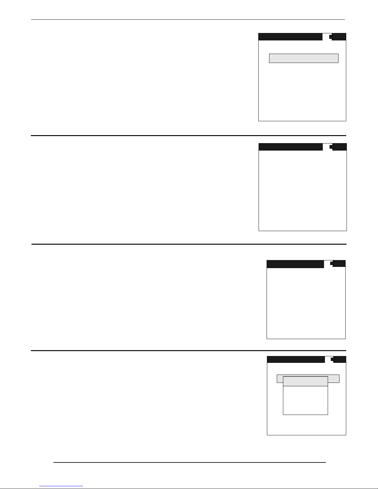
SAIC Exploranium – GR-135 System Manual page: 42
11.0 MAINTENANCE
This section has a selection of special utility programs for special
functions
11.1 MAINTENANCE MENU
This is the main Maintenance menu – see fig. 36
11.2 LIBRARY
Selection of this option displays the nuclides in the system library
– see Fig. 37. For the current library list refer to Appendix D
11.3 CHARGING
This special feature is used during system setup
IT IS NOT RECOMMENDED FOR GENERAL USE
AS IT CONTAINS NO USEFUL INFORMATION
FOR THE NORMAL USER.
11.4 REMOTE
This sets the RS232 port to the active state to permit data transfer
using the Exploranium IdentiView software described in Appendix B.
This setting works as a latch – the first activation sets the port
ACTIVE and the next activation sets it INACTIVE. Normally the
port should be INACTIVE for normal system functions.
In the system architecture the RS232 port and the AUDIO sound
share a common data point. This is normally not an issue as the
Audio is not normally active during RS232 functions.
Users are advised that when the REMOTE mode is active, the AUDIO is disabled.
MAINTENANCE
LIBRARY
CHARGING
REMOTE
DEFAULT
ADC TEST
MAIN MENU
Fig. 36
LIBRARY
STANDARD LIBRARY
U-238 RA-226
TH-232 K-40
CE-139 I-131
CS-137 CO-60
BA-133 TC99M
CO-57 AM-241
XE-133 NP-237
PD-103 IR-192
ENTER TO GET MORE
Fig. 37
CHARGING
BAT VOLTAGE 243
EL.METER 01273
EXT.POWER OFF
CHARGING OFF
CH.TIME 00000
REFRESH OFF
ERR.STATUS 02
Fig. 38
MAINTENANCE
LIBRARY
MESSAGE
CHARGING
REMOTE
REMOTE
MODE
DEFAULT
ACTIVE
ADC TEST
MAIN MENU
Page 43

SAIC Exploranium – GR-135 System Manual page: 43
11.5 DEFAULTS
This selection permits the user to LOAD DEFAULT PARAMETERS.
This is sometimes useful when the instrument has not been used for
a long period or when “strange” system performance occurs.
Like all computer-based systems, sometimes the data memory gets
corrupted. The system software checks all functions continuously to
try to trap any problems that could cause memory corruption but not
all features can be protected against.
For these reasons sometimes it is necessary to clean the entire
system memory and load the basic Default parameters.
This is done by selecting this function and a new figure appears
NOTE – LOADING DEFAULT PARAMETERS ERASES ALL DATA
MEMORY SO IF NECESSARY THE USER SHOULD SAVE THE DATA
USING IdentiView BEFORE LOADING DEFAULTS
As the display shows, press ENTER 3 times to activate this feature.
The screen then shows the figure on the right. The unit will return
to the Maintenance screen when defaults have been loaded.
11.5 ADC TEST
This special feature is used during system setup
IT IS NOT RECOMMENDED FOR GENERAL USE
AS IT CONTAINS NO USEFUL INFORMATION
FOR THE NORMAL USER.
MAINTENANCE
PUSH ENTER THREE TIMES
TO LOAD DEFAULT
OR UP ONCE
TO EXIT
Fig. 39
.
MAINTENANCE
DEFAULT LOAD ROUTINE
ENGAGED
WAIT UNTIL FINISHED
Fig. 40
ADC TEST
CH 15 CNT 1
CH 28 CNT 1
CH 30 CNT 1
CH 34 CNT 1
CH 40 CNT 1
CH 47 CNT 1
MAX 48 CNT4
F GAIN 512
TOT.COUNT 32
GM-DET 0 NEV 0.000
LIVE TIME 949
COSMIC 1
CONTRAST 32
TEM P 25 27 24 VOL T 241
PILEUP 0
Fig. 41
Page 44

SAIC Exploranium – GR-135 System Manual page: 44
12.0 SPECIFICATIONS
DETECTORS
a) SODIUM-IODIDE
Detector: Sodium Iodide (Thallium) [NaI(Tl)] 4.0 cu ins ( 65 cm
1.5" diam * 2.2” long (38 mm dia x 57mm long) with an integral bi-alkali PMT.
Resolution: Better than 9.0 % FWHM for Cesium 137 at 662 keV.
b) G-M tube : 0.5” diam x 2” long – energy compensated GM tube
Range – 1mR/h to 10R/h for Cesium-137
c) NEUTRON detector (optional): solid state N detector coupled with a miniature PMT
0.86” long by 0.7” diam.
Sensitivity : ITRAP spec – will alarm on a 20KN/s source at 25cms in 5 seconds
d) CZT detector (optional) : 10x10x5mm CZT Capture detector
Resolution: Better than 11.0% FWHM for Barium-133 at 81 keV.
ANALOG TO DIGITAL CONVERTER
Type: Buffered, high speed, high linearity, 8 ΦS - Successive Approximation ADC.
# of channels: 1024
Lower threshold: Internally adjustable – set at 15keV
Upper threshold: Fixed to Ch 1023, all pulses above this level are Cosmic and are accumulated
and displayed in Channel 1024.
ADC Offset: Internally adjustable.
Maximum Count per Channel: 65,535
Dead Time Correction: Automa tic, 0.1% precision.
DOSEMETER
Sample time: 1, 2, 3, ... , 10, 20, 30, ... , 60 s
Energy range : 50 keV - 3.0 MeV set by the spectrometer
Meas. units: Selectable R, Sv, Gy.
Meas. range: Sodium-Iodide only: 1 µR/h - 5 mR/h
System may overload at the higher level at a different rate depending on the
isotope. Approximate
maximum levels are 2mR/h for Am-241 and 5 mR/h for
Cs-137.
Meas. Range : G-M tube : 1 µR/h - 1 R/h (10nSv/h – 10mSv/h)
3
) volume detector
Page 45

SAIC Exploranium – GR-135 System Manual page: 45
Precision (NaI) :
±10% in range 100 keV - 3.0 MeV
±20% in range 60 keV - 100 keV
Output: Memory or PC.
MISCELLANEOUS
CLOCK - CALENDAR
Type: Built in 24-hour clock, 4-year calendar (including leap year).
Full battery backup, 10 year retention time.
Precision: +/- 3 s/day at 25 deg. C.
+/- 30 s/day over full operating temperature range.
DATA STORAGE
Type: 2MB CMOS SRAM memory, with Li-battery back-up.
Capacity: 40,000 samples, including time/date (SEARCH+DOSE mode)
or
187 spectra ( IDENTIFY mode - 1024 channels ), including time/date
Data Retention Time: Typically 10 years, limited by Li-battery life.
Stored Data Retrieval: Via serial channel to a computer.
DATA OUTPUT
Type: Serial channel RS-232C, 1 start bit, 8 data bits, no parity, 1 stop bit.
Baud Rate: 19200 Bd.
Format: Binary data in packets - see Appendix I.
GENERAL DATA
DISPLAY
Type: WTSTN (Wide Temperature Super Twist Nematic) graphics LCD, 128 x 128
Contrast: Digitally adjustable in 20 steps, by joystick in selection menu.
POWER REQUIREMENTS
Battery voltage = 3 V
Power usage OPERATION NORMAL
Measurement: 0.65 W 1.2 W
Main menu and
all setting menus: 0.35 W 0.7 W
pixels, LED backlight. Viewing area: 67 x 67 mm.
Page 46

SAIC Exploranium – GR-135 System Manual page: 46
POWER SUPPLY OPTIONS
A.
Internal Rechargeable Battery
Type: 2 "D" cells, 1.25 V NiCd.
Operation time: Typically 8 hours of operation at 25
o
C, no backlight, 4 AH NiCd.
Charging: External, constant current float charger, overnight charging,
full charge indication by LED.
B. Internal Battery
Type: 2 "D" cells, alkaline.
o
Battery Life: Typically 15 hours of operation at 25
C, no backlight,
with Alkaline EVEREADY #1250.
C. External
:
Type: 12 VDC, 1.0A external power supply
Voltage Range: From 9-24VDC.
CONNECTORS
Charger (Ext. Power Supply): 2.5 mm power circular jack, "+" on the center pin.
Mating connector: 2.5 mm power circular plug.
Serial Channel: 3.5 mm stereo jack.
Mating connector: 3.5 mm stereo plug.
Docking Station: 4 spring loaded pins for power and RS232
PHYSICAL
Dimensions: L = 9.25" (235 mm)
W = 4.5" (110 mm)
H = 3.9" (100 mm), 6.75" (170 mm) including handle
Weight: 1.9 kg ( 4.4 lbs) without battery.
2.4 kg ( 5.5 lbs) including battery.
ENVIRONMENTAL
Operating Temperature Range: - 10 to + 50
o
C
o
Storage Temperature Range: - 20 to + 60
C
Protection: Weather proof , dust and water sealed (no immersing).
Non-condensing Relative Humidity: Less than 90% at 40
o
C.
Vibration: 0.5G max. (10 - 300 Hz, XYZ directions, 1 h)
Shock: 3G (10 mS, XYZ directions, 1 time each).
RFI/EMI Emission: Complies with FCC rules (47 CFR Part 15) for class A.
Full CE Certification
Page 47

SAIC Exploranium – GR-135 System Manual page: 47
ACCESSORIES
Standard: - GR-135 Unit.
- 110VAC Charger Adapter for battery charging.
- Vinyl carrying case.
- CD-ROM with IdentiView Windows software.
- RS-232 cable for PC connection.
- Reference Source Cesium 137 (0.25 µCi).
- Operating Manual.
- Padded, compartmentalized carrying case.
Optional: - 220 VAC Charger Adapter for battery charging.
- DOCKING STATION for automatic charging and PC connection
- External earphone system
- 2uCi Cs source if permitted by local regulations
Page 48
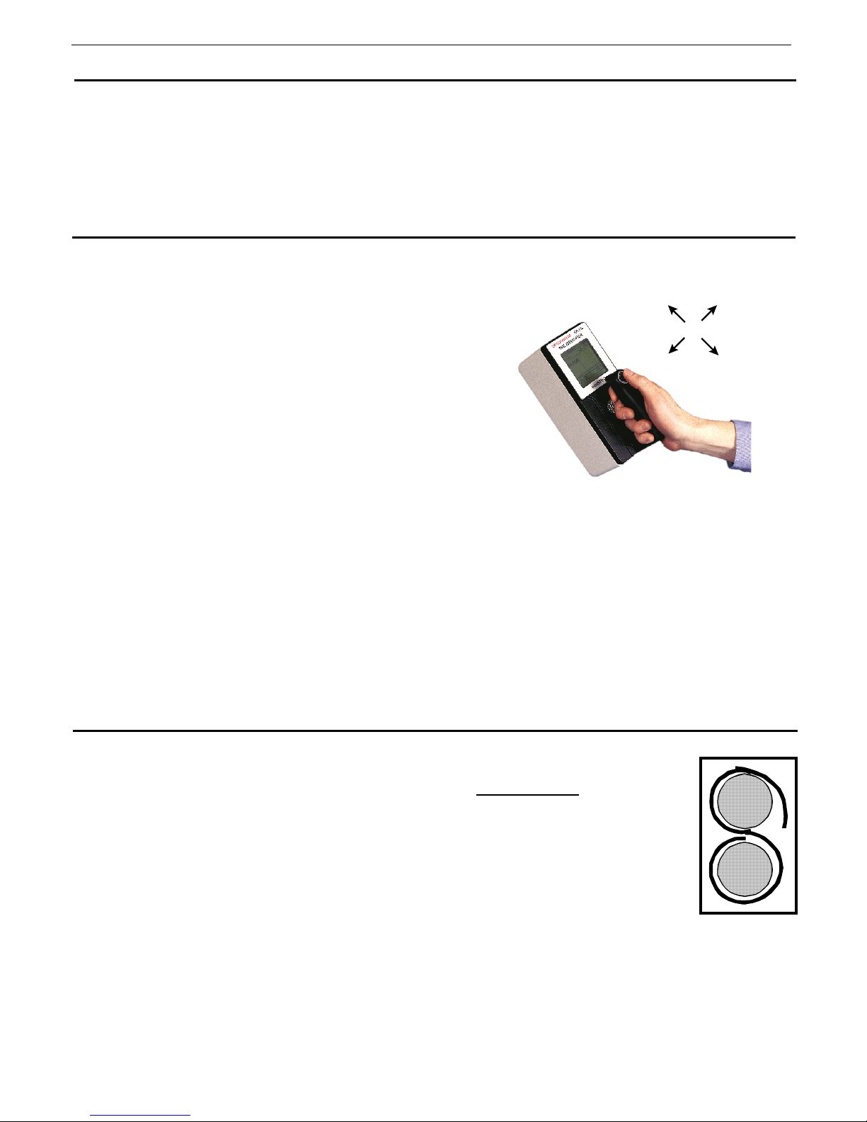
SAIC Exploranium – GR-135 System Manual page: 48
APPENDIX A - AUTOMATIC MODE OPERATION
GENERAL: this mode was developed for semi-technical users who only require a limited number of
instrument functions and do not want to select relatively complex system functions and
parameters.
The operating parameters are selected by a local technical person to suit the application and then
the system is set into the AUTOMATIC operating mode. Operating functions are described
below.
A.1 JOYSTICK
The GR-135 is equipped with a rubber-covered
JOYSTICK on the instrument handle, referred to in
this manual as the JOYSTICK and this is the ONLY
control on the instrument. The great advantage of
this single button control is that besides being very
easy to use it also permits full operation EVEN
WEARING GLOVES – a definite advantage in many
applications where protection clothing is required.
As the figure shows
(away from you) and
are the 4 normal actions of the joystick. For
mechanical reasons the user can also press the
button
IN (into the handle) BUT THIS
HAS NO EFFECT AT ALL.
For ease of use the system is arranged so ANY ACTION EXCEPT UP – is considered an action and
is referred to in this manual as
you) any of these actions act as an
pressing the button DOWN is the easiest)
LEFT, RIGHT, UP
DOWN (towards you)
JOYSTICK ACTIONS
ENTER. This means that LEFT/RIGHT and DOWN (towards
ENTER command to the system. (Most users find that
UP
(away
from you)
LEFT
RIGHT
DOWN
(towards you)
Once again - IN has NO FUNCTION
A.2 LOADING BATTERIES
To load batteries, remove the battery backdoor at the rear of the instrument by
applying a ¼ turn to the door lock. Insert the two rechargeable
with the "+" to the small brass ring and the “-“ to the spring. The fabric strip
should be placed BEHIND the batteries to aid in their removal in an “S” fashion to
be able to remove each battery separately (see fig).
Ensure that both batteries are firmly seated, attach the plastic battery retainer clip
then re-attach the door.
D-cell batteries
Page 49
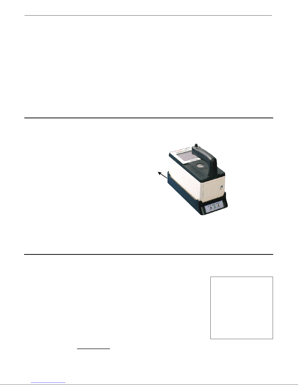
SAIC Exploranium – GR-135 System Manual page: 49
A.3 SETUP DOCKING STATION (DS)
Place the DS at a convenient location, connect the supplied AC plug into an AC socket then plug it
into the DS. If data retrieval is required, also attach the supplied 9 pin cable to yo ur computer
RS232 port (see Appendix B for computer software installation and description)
Observe the lights on the front of the Docking-Station labeled – ERROR, POWER, CHARGE
Correct operation after power connection
WITH NO UNIT IN THE DS is –
ERROR (RED) – flashing
POWER (GREEN) – on
CHARGE (YELLOW) – off
A.4 PLACE UNIT IN DOCKING STATION
Remove the YELLOW protective
“boot” from the instrument that
exposes the 4 “pads” on the base of
When not in active use the GR135 stays in the
Dockin g Station
the unit. Note the 4 “pins” on the
base of the DS.
Place the GR-135 unit in the DS so
DS 115V A C
wall plug
the pads match the pins (the rim
around the DS ensures that correct
positioning of the unit in the DS is
very easy).
The audio should beep as the unit is
automatically switched ON as it is
seated in the DS
GREEN
light = power ON
YELLOW
light = cha r gi ng
The front panel CHARGE (YELLOW)
light on the DS should come ON to
show that the batteries are charging
A.5 STARTUP DISPLAYS
The unit automatically switches on when it is placed in the DS and various displays are seen:
a) STARTUP – this display appears for only a few seconds. Data
shown are:
GR-135 – instrument name
VERSION 104 – the software version in the unit
SER# 2001 – the serial number of the unit
AUTOMATIC MODE ACTIVE – shows the unit is in the
AUTOMATIC
mode of operation
EXPLORANIUM
GR-135
The IDENTIFIER
VERSION 104
SER# 2001
AUTOMATIC MODE ACTIVE
Page 50
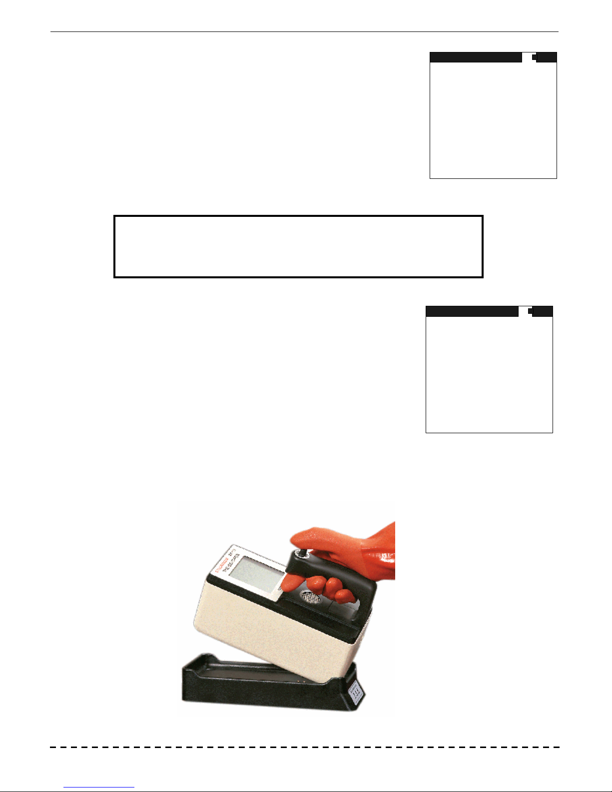
SAIC Exploranium – GR-135 System Manual page: 50
b) WARMING UP
After the Startup screen is seen a new display appears as shown.
WARMING UP
As specified in the display, the system is warming up so WAIT.
During this time the system is automatically adjusting its internal
parameters as well as charging the batteries
SYSTEM NOT
READY
This basic process should take approximately 2 minutes but users are
recommended to leave it in the DS for approximately 1 hour before
starting any system operations to give the batteries time to take a
WARMING UP
WAIT
charge
Note that this “warm-up” mode only occurs when the unit is first put in use or if the unit has been
left out of the DS for an extended period of time (see section 10.2)
NOTE:
LEAVE THE UNIT IN THE DS WHEN NOT IN USE
c) SYSTEM READY
Once the system has AUTOMATICALLY adjusted the basic system
parameters correctly, the display shows :
SYSTEM READY – means that internal parameters are set correctly
REMOVE WHEN REQUIRED – means the unit is ready for use. As commented above if this is a
first time use, it is good practice to leave the unit in the DS for 1 hour to get some level of
battery charge.
When the unit is removed from the DS, system operation is automatically started in the SEARCH mode.
WARMING UP
SYSTEM
READY
REMOVE WHEN
REQUIRED
Page 51
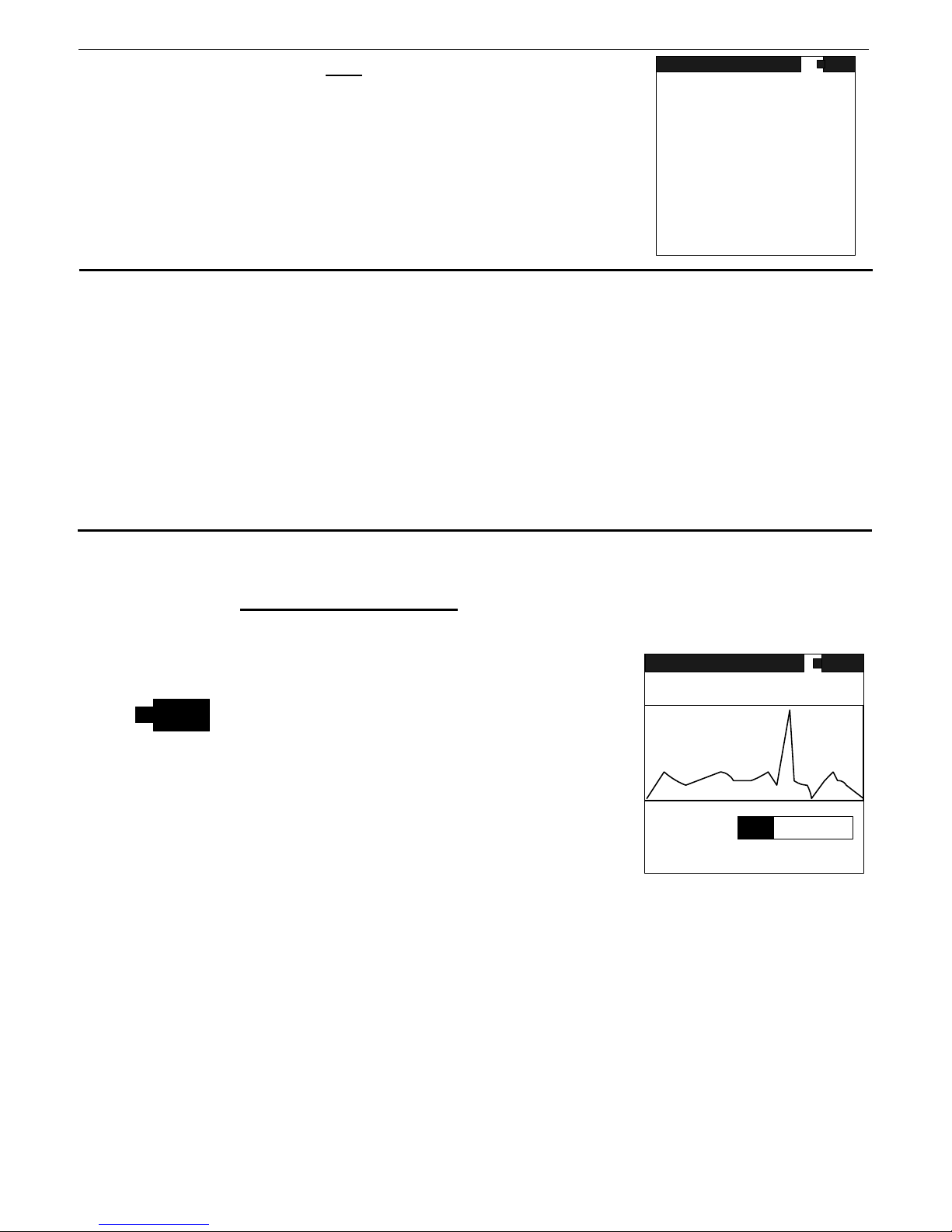
SAIC Exploranium – GR-135 System Manual page: 51
d) POWERING ON WHEN NOT in DS – normally the GR135 needs to
WARMING UP
be in the DS when not in use. System parameters normally require
being in the DS at least once every 24 hours. If this time is
exceeded a special message is seen (see figure).
SYSTEM NOT
READY
As noted on the display, users should place the unit IN the DS and
then the system will automatically adjust itself (minimum period ion
the DS = 2 minutes but longer is recommended for battery
PLACE UNIT IN
DOCKING STATION
charging).
A.6 SYSTEM USE
The GR-135 in the AUTOMATIC mode only operates in 2 modes – SEARCH and IDENTIFY
The SEARCH mode is used to search and locate radioactive material in vehicles, packages or on
people etc. The user can easily scan the suspect item and look for a significant increase in radiation
using the tools described in the SEARCH section below.
Once a source of radiation is found, the SEARCH mode is used to find it’s maximum point and then
the user selects the IDENTIFY mode.
As described in detail below, the IDENTIFY mode takes a sample (usually for 60 seconds) then
automatically analyses it and advises the user of the details of any radioactive material found.
A.7 SEARCH MODE
This special mode is used for searching for radioactive material. When the unit is removed from the
DS this mode is automatically selected
Data displayed are:
SEARCH – the function currently activated (i.e. SEARCH)
and the display shows the SEARCH display (see fig).
SEARCH
TOTAL 1234
MEAS
VS 2K
- a battery icon that shows battery status.
TOTAL – an operating mode set by the supervisor
1234 – this is the radiation level in cps (counts per second).
This level will always show some counts even if no
apparent radioactive material is present as this is the
local radiation background of an area. Typically in low
D.RATE
173
500
uR/h
PRESS ENTER TO IDENTIFY
background areas, 50-100cps are common.
MEAS – shows that measurement is in progress
VS 2K – shows that the vertical scale on the chart display below is 2K (2000cps). This scale will
change automatically as radiation increases so the chart will always contain the peak
radiation
CHART DISPLAY – this is a chart display of the radiation data. The bottom of the chart is ZERO
cps and the top of the scale is automatically scaled. The display moves from left to right
so the LEFT hand data is the current data. The chart shows the last 120 samples and is
a very useful “view back” at the data making it very easy to see any significant radiation
increases. Note that the numeric cps data is not energy dependent so very small
changes of any type of radioactive material emitting gamma rays can be easily seen.
Page 52
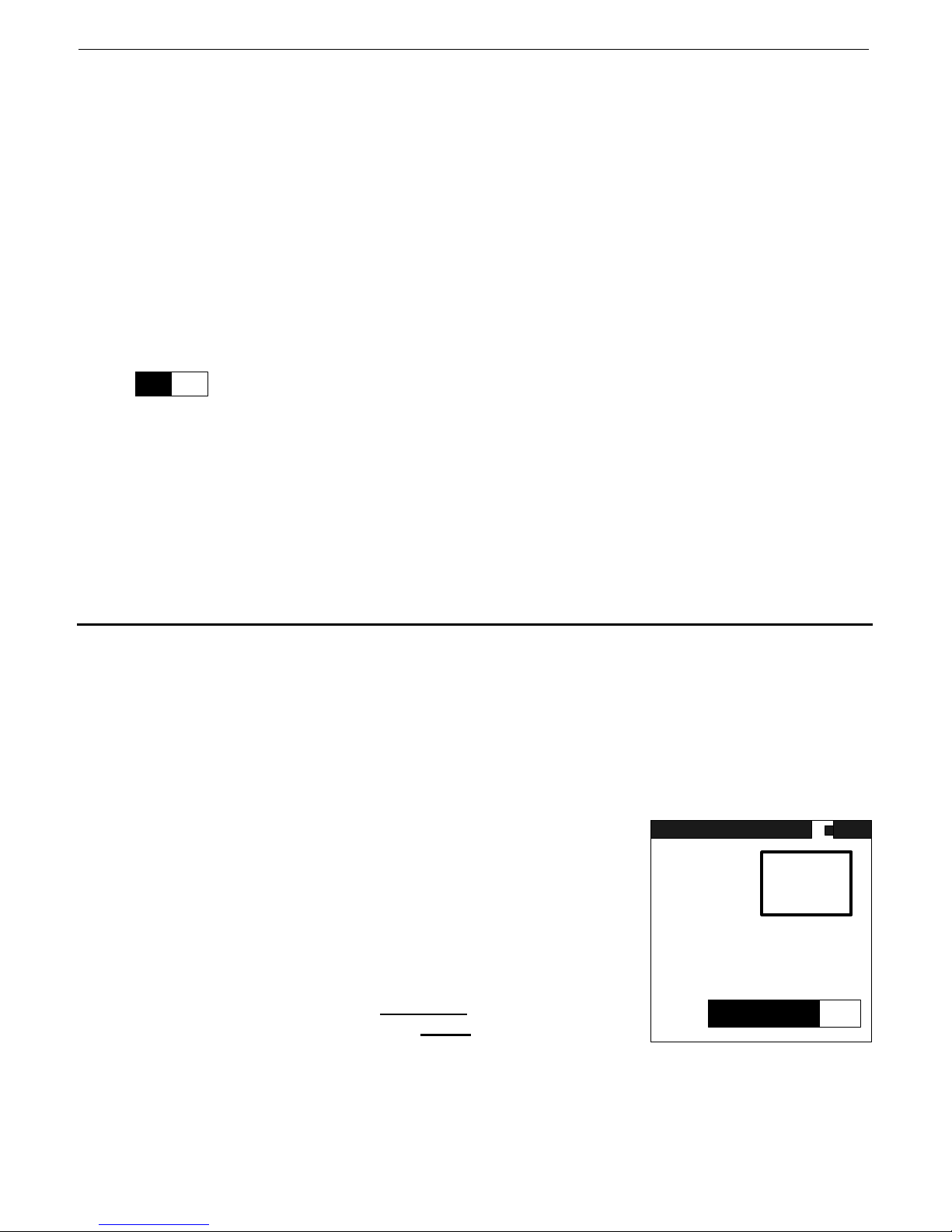
SAIC Exploranium – GR-135 System Manual page: 52
D.RATE – the bar display and the numeric data show the Dose Rate data. The numeric data
shown above (1234cps in the figure) is an essential tool to locate radioactive material
but the DOSE data gives the user an idea of the potential hazard level of such material.
173uR/h – this is the numeric value of the Dose Rate in the selected units, in this case
Roentgen/h usually referred to as R/h. Many users find the numeric display useful but
some users find it’s changing units gets confusing which is why the bar graph and the
numeric data are both shown
500 - this shows the defined limit selected by the system supervisor that is the maximum
range on the bar graph. If this limit is exceeded a special alarm occurs (se below).
Note that this user is in the units selected – in the display shown – since the D.RATE is
in uR/h then the 500 = 500uR/h. At this setting, if the DOSE RATE exceeds 500uR/ h
then the warning alarm will occur (see A.10 below)
PRESS ENTER TO IDENTIFY - pressing the JOYSTICK is referred to as ENTER, so the user is
- this bar graph gives the user an easy visual display of the Dose hazard level (Zero on the
left and Maximum on the right). The users technical personnel determine at what
Maximum Dose level their personnel are permitted to work in. This is then set in the
system parameters and defines the upper level of this bar graph. Once the is limit is
exceeded the user is warned – see the HIGH DOSE section A.10 below
advised that pressing ENTER will change the operating mode to the IDENTIFY mode
described below. As noted above, when the center of the radiation is located in the
SEARCH mode then the user presses ENTER to analyze the radiation as explained
below.
A.8 IDENTIFY MODE
When this mode is activated from SEARCH by pressing ENTER, a new display appears:
IDENTIFY – shows the mode of operation (IDENTIFY)
SAMPLE IN PROGRESS WAIT – advises the user that a sample is in progress for the time
period set in the unit so the unit should be held in a fixed position to enable a proper
sample to be taken.
IDENTIFY
OK – this flashing box advises users of a way to get the best
sample. The system has internal parameters that assess
detector functions. If OK is shown this means that the data
accumulation is OK for good system analysis.
Alternative displays in this box are :
MOVE CLOSER – means that the signal is very weak
so if possible
the unit closer
of radiation. In many cases this is
impossible so no action need be taken, but if possible move the unit
closer until the display shows OK
MOVE AWAY – means that the signal is stronger than is necessary to take a proper
sample. Correct action is to back away until the display shows OK.
the user should move
to the suspect source
DET: NAI
SAMPLE IN
PROGRESS
TIME
1
MIN
OK
WAIT
Page 53

SAIC Exploranium – GR-135 System Manual page: 53
TIME this shows the selected sample time, in this case 1 minute. Thus the progress bar
1 shows the progress of the 1-minute count time
MIN
the progress box shows the time progress to the end of the sample period (1 minute
in the example)
A.9 RESULTS
After the sample time is complete the system automatica lly
the data to determine the isotope of the material and displays the
results as shown.
analyses
NUCLIDE IDENT
TYPE ISOTOPE
I ND Cesium-137
TYPE – shows the category of the isotope identified.
Labels used are :
- IND – Industrial isotope
- MED – Medical isotope
- SNM – Special Nuclear Material
ISOTOPE – is the actual name of the isotope
SPECTRUM STORED AS #6 - every time an IDENTIFY analysis takes place the radiation data
(spectrum) from this analysis is stored in memory where it can be accessed with special
software for subsequent analysis by the users radiation experts as required. The display
advises the user what the data set is with the label SPECTRUM #6. This number can be
anywhere from 1 to 999 and serves to uniquely identify the data in system memory for use
during data retrieval and analysis.
An additional feature is that under special conditions the user may see various special nuclear
items that are NOT included in the system library. In this case the manufacturer can
analyses these data and if required the internal analysis library can be updated so in future
this type of material would be identified.
UP TO REPEAT SAMPLE – sometimes if the radiation levels of the material being analyzed are
very low, it is possible that, at the end of a 60 second sample p eriod, the analysis of the
sample may show NO NUCLIDES FOUND. In some cases the user may wish to take a
longer sample to improve the analysis.
If the button is pressed UP (away from the user) then a second sample takes place. If the
system is set for a 1 minute sample time then pressing UP will take an additional 1 minute
sample, add it to the original sample to produce a 2 minute sample, store this in a second
spectrum in memory and carry out NUCLIDE IDENTIFICATION again. Perhaps this time the
improved data quality from a longer count will permit an identification to be performed.
This UP (to repeat the sample) can be performed as often as the user requires to build up a
larger and larger sample for analysis.
PRESS ENTER TO SEARCH – pressing ENTER moves the user to the SEARCH mode again
UNKNOWN ISOTOPE
The GR-135 has a wide selection of radioactive isotopes in its internal library. However it is possible
that a very rare isotope can be encountered. In this case the system cannot identify the isotope so
the message UNKNOWN ISOTOPE is displayed. If this message is seen we recommend that you
retrieve this stored spectrum and send it to [email protected]
SPECTRUM STORED AS #6
UP TO REPEAT SAMPLE
PRESS ENTER TO SEARCH
at Exploranium for further analysis.
Page 54
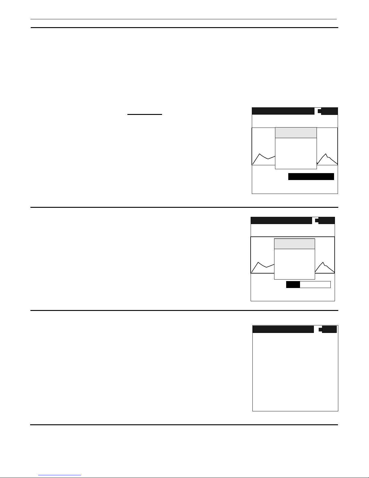
SAIC Exploranium – GR-135 System Manual page: 54
OTHER FEATURES:
A.10 HIGH DOSE
The system has a preset maximum Dose Rate level – normally set at 2000µ/R. Below this level
Dose Rates are considered acceptable for system operation. However above this level it is
recommended that users move away from the source of radiation to reduce this Dose Rate level
to an acceptable level. To make things simple, the GR-135 advises the users automatically if the
Dose Rate level goes above the preset limit.
If the level is exceeded a distinctive
audio warning tone occurs
and the display changes (see fig)
As noted the user should back away until the Dose Rate level falls
below this limit and the display warning goes away.
Note that the lower Dose Rate bar graph also shows t hat the
Dose rate is at or above the preset limit.
Users should be reminded that short-term operation close to the
limit has a negligible hazard level but prolonged operation
significantly above this level is not recommended
A.11 NEUTRON ALARM
If the integrated Neutron detector computes an alarm above it’s
preset alarm threshold then a Neutron Alarm is declared. A
distinctive audio warning tone occurs and the display changes
(see fig).
A.12 NEUTRON S DETECTED DURING IDENTIFY
If any Neutron activity is detected during IDENTIFY this data is
shown on the display – see Fig.
Since the IDENTIFY period is for typically 55 seconds as opposed
to the SEARCH analysis which is only for a few seconds, a weak
Neutron source may be detected in the IDENTIFY mode of
analysis where it may be missed in the SEARCH mode.
The display shows the Neutron activity in DOSE units to give an
idea of the relative intensity of the Neutron activity. However
many users set the system for counts/second (cps)
TYPE ISOTOPE
NEUTRONS 0.452uSv/h
SEARCH
TOTAL
DOSE
12345
WARNING!!
HI RADIATION
DOSE RATE
MOVE AWAY!!
MEAS
VS 2K
4215
uR/h
PRESS ENTER TO IDENTIFY
SEARCH
TOTAL 12345
WARNING
NEUTRONS
DETECTED
DOSE
MEAS
VS 2K
173
uR/h
PRESS ENTER TO IDENTIFY
NUCLIDE IDENT
I ND Cesium-137
ENTER TO CONTINUE
Page 55
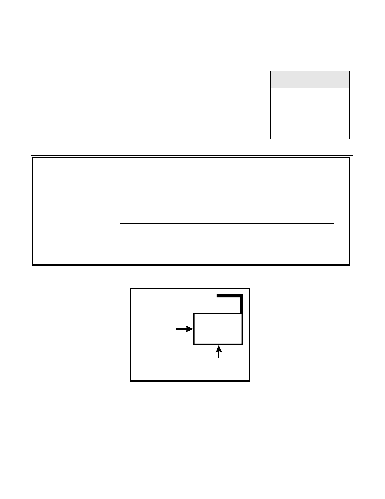
SAIC Exploranium – GR-135 System Manual page: 55
A.13 AUTOMATIC CZT DETECTO R ACTIVATION
The system has a special high sensitivity detector located inside. Special analysis determines the
special case where using such a detector will improve system analysis. If this occurs the actual
operation will be as follows:
- Unit takes the normal 55 second analysis and computes the
results
- Normally the Nuclide ID results are displayed
- However if the analysis determines that CZT is required the
unit will:
- beep 3 times as a warning
- automatically change detectors
- the display will show DET=CZT and a pop-up menu
(see fig) will appear to warn the user that CZT data
analysis will now take place.
MESSAGE
CZT DETECTOR
ACTIVATED
ENTER TO
START CZT
NOTE
CZT ANALYSIS IS REQUIRED UNDER SPECIAL CONDITIONS WHERE IT IS
POSSIBLE THAT SNM MATERIAL IS PRESENT. THE CZT DETECTOR IS A
RELATIVELY HIGH RESOLUTION DETECTOR AND THUS USING ITS DATA CAN
ENHANCE DATA ANALYSIS. HOWEVER IT IS VERY INSENSITIVE SO A LONG
COUNT TIME IS REQUIRED SO THE SYSTEM IS USUALLY SET FOR A 5 MINUTE
CZT COUNT TIME. 5 MINUTES IS A LONG TIME TO HOLD THE INSTRUMENT
AGAINST SOMETHING SO MOST USERS PREFER TO PROP THE UNIT IN PLACE
DURING THIS LONG ANALYSIS PERIOD. ALSO THE CZT DETECTOR IS LOCATED
AT THE BOTTOM OF THE INSTRUMENT SO THE INSTRUMENT SHOULD BE
POSITIONED ACCORDINGLY
- position the detector as required (see figure)
- press ENTER to start the automatic CZT analysis
- at the end of the CZT count period, the CZT spectra is stored and this spectrum #
is shown on the display as usual. Note that the original NaI spectrum was also
stored so at the end of the CZT spectrum period, the displayed stored spectrum #
is for the CZT and the one before is the NaI spectra. Thus if after CZT analysis
the spectra is stored as SPECTRUM #9 then SPECTRUM #8 is the related NaI
spectrum
- after data storage the spectra from the NaI and CZT are automatically analyzed
and the combined result shown to the user on the display
OPTIMUM
NAI ANALYSI S
DIRECT ION
GR-135
OPTIMUM
CZT ANAL YSI S
DIRECT ION
Page 56

SAIC Exploranium – GR-135 System Manual page: 56
A.14 POWER OFF - MANUAL
To power the unit OFF, IT MUST BE REMOVED FROM THE DS UNIT. Then
CLICK UP (away from the user) and hold for 4 seconds. The display will
show a special display (see Fig.) with the seconds counting down; 3, 2, 1.
After this countdown the unit powers OFF. At any time during the
countdown, releasing the JOYSTICK will cancel the power OFF.
A.15 BACKLITE
A BACKLITE option is built into the GR-135 such that the display may be viewed in low light
conditions. BACKLITE can be enabled in the system setup for frequent use or as shown below for
intermittent use.
To switch the BACKLITE on it is first necessary to switch the unit OFF as described above in A13.
With the unit OFF, press ENTER and HOLD the JOYSTICK in this position. After about 4 seconds
the display will be illuminated, after which the JOYSTICK may be released. The BACKLITE will
remain active until the unit is powered OFF.
The GR-135 has a built-in battery saving feature such that the BACKLITE will not turn ON if the
battery voltage is below 2.2 V. This low voltage indicates that there is little battery life left so
disabling the BACKLITE feature allows the user to use the remaining battery life optimally. No te that
to turn off the BACKLITE, the unit must be switched OFF then switched ON again with the normal
short click action.
The BACKLITE feature may be selected to be ON all the time for some applications but users
should be aware that enabling the BACKLITE feature reduces battery life by an estimated 50%.
A.16 LOW BATTERY WARN INGS
The Battery ICON at the top right of the display is intended to provide the user with an idea of the
current battery status. For convenience, most users tend to use the NiCd rechargeable batteries. To
provide some level of warning of imminent battery life - if the batteries fall below a certain level then
a 3-beep audio occurs and the Battery ICON changes to the message LOW. The user has between 2
and 10 minutes of measuring time left in the battery at this time. When there is no longer enough
power to allow measuring, the GR-135 turns off.
TURNING OFF
3 (2,1..)
Full Charge ½ Charge Low Battery Warning
LOW
Battery Icons
A17. PROBLEMS
NOTE
LIKE ANY COMPUTER BASED SYSTEM IT IS POSSIBLE THAT A SPECIAL
COMBINATION OF EVENTS CAUSES THE SYSTEM TO “HANG-UP”. IF THIS
OCCURS – POWER THE UNIT OFF AS DESCRIBED IN THIS SECTION AND
THIS WILL OVERRIDE ANY INTERNAL PROBLEMS AND SHUT THE SYSTEM
DOWN. THEN POWER ON AS USUAL AND ALL SHOULD BE OK.
Page 57
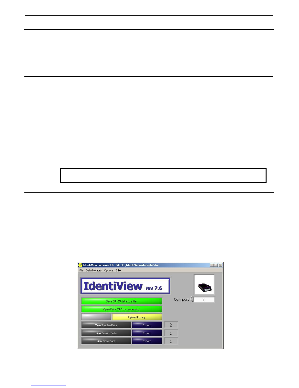
SAIC Exploranium – GR-135 System Manual page: 57
APPENDIX B - IDENTIVIEW SOFTWARE
1. GENERAL
IdentiView is a specially designed software program supplied by Exploranium that is used to
download data from the GR135 instrument and view/analyze/format the data. In t his version of
software documentation it is assumed that the user is ALWAYS in the AUTOMATIC MODE and only
spectra will be downloaded. For MANUAL mode operation, the procedure for downloading data from
the GR-135 is identical except that the GR-135 must first be set to the REMOTE data access mode.
2. Installing the Software
1. Load the Exploranium “Program/Document Support” CD into the PC.
2. Select RUN and BROWSE, then navigate to the GR135\Software\Identiview release
version xxx\disks directory, where xxx is the version number. Select the file setup.exe
and click OK.
3. Select desired install location (default = C:\IdentiView).
4. Click FINISH. After some screen activity, the screen should show “Successful
Installation”.
5. Once the IdentiView Application program appears, right-click and use “Send-to” to
setup an icon on the Desktop.
6. Close this window.
7. Follow screen prompts to install the LabView engine software.
8. Exit all screens.
Note: The GR135 is hard-wired to operate at 19200 Baud to suit most computers.
3. USING THE SOFTWARE IN AUTOMATIC MODE
3.1 SETTING UP THE SYSTEM
Set up the system as follows:
1. Connect the DS to the PC com port via the supplied 9 pin cable.
2. Apply power to the DS with the power cord. The green light should be on.
3. Click the GR135 joystick button down for at least 2 seconds. The unit will power ON and
after a few seconds the SYSTEM READY message appears.
4. Start the program by clicking the IdentiView icon. The following screen appears.
Fig. B1
Page 58
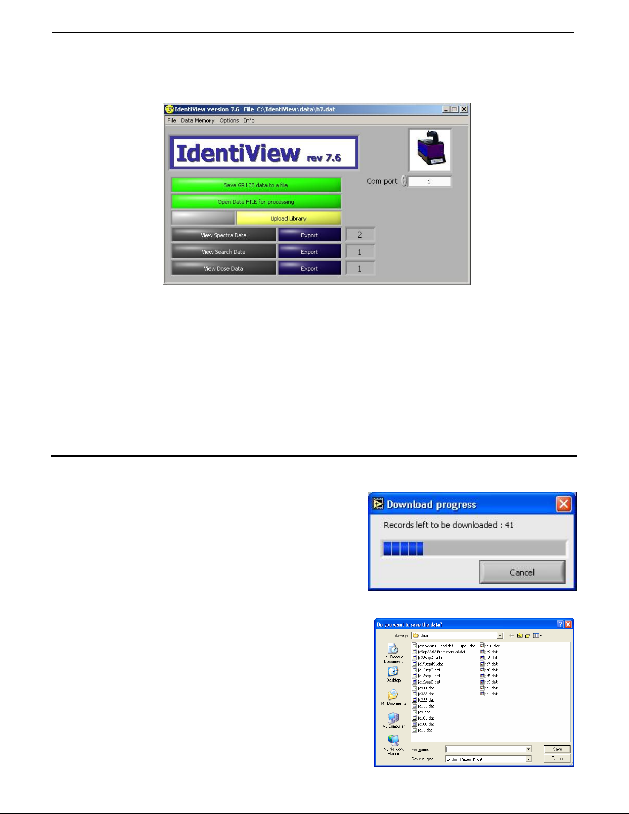
SAIC Exploranium – GR-135 System Manual page: 58
The icon in the top right-hand corner of the display indicates when the GR135 IS NOT in the DS,
or if it is not communicating with the PC. If the unit IS in the DS then this graphic is replaced
with an icon depicting the unit in the DS as shown below:
Fig. B2
If the correct icon as in Fig. B2 is NOT seen, check:
that the GR135 is correctly placed in the DS
the DS is cabled to the correct COM port (to check this change the COM port
settings on the IdentiView screen)
that the DS and the GR135 are both powered on.
If the icon is still not visible, remove the GR135 from the DS and power off. Exit the software
(File/Exit), restart the software, then place the GR135 in the DS. If the icon is still incorrect,
contact Exploranium.
3.2 DOWNLOADING DATA
- As soon as the IdentiView software recognizes
that the GR135 is in the Docking Station it
automatically starts to download the data and
the following display appears:
- The program is downloading the data at approx
1 spectra/second.
- At the end of data transfer the following screen
on the right appears.
- Enter an appropriate location and filename and
click “Save”.
- The default file location is C:\Indentiview\Data.
- Enter an appropriate location and filename and
click “Save”.
Page 59
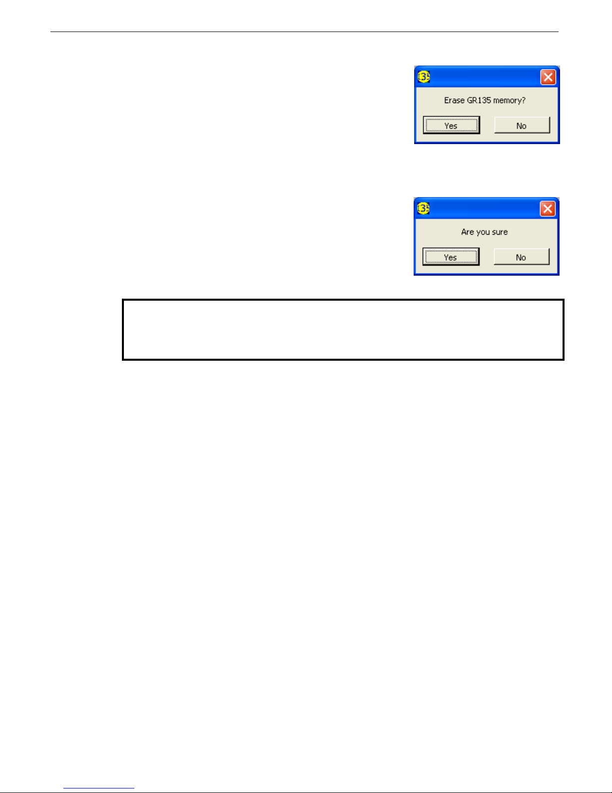
SAIC Exploranium – GR-135 System Manual page: 59
- Once the data is saved a new message appears. This
permits the user to erase all the spectra in the data
memory of the GR135. This is usually a good idea as
once the data is transferred then it is not really necessary
to keep it in the 135. In addition if the memory is not
cleared then next time data is transferred the same
spectra will be downloaded again (plus any new spectra
recorded since the last download). Eventually data transfer will be very time consuming
as the system memory can accommodate 187 spectra (187 secs to download!).
- If YES is selected a second message appears to ensure
that this is the preferred action
- Click “NO” to NOT erase the memory
NOTE: Normally, erasing the data is the correct action. However, these spectra are
important evidence of an event, so the following procedure is recommended.
- Inspect the data
- Once you are confident all is OK, select “Data Memory Erase” from the main menu and
erase the data.
Checksum
Checksum is a simple error-detection scheme in which each transmitted message is accompanied by a
numerical value based on the number of set bits in the message. The receiving station then applies the
same formula to the message and checks to make sure the accompanying numerical value is the same.
If not, the receiver can assume that the message has been garbled.
IdentiView has two checksum processes:
• Transfer — occurs during RS232 download only. A transfer error can occur due to improper
packet transfer action. If this happens, you can recover from the error: don’t erase or download
the data again.
• Data record — occurs when opening a data file or while viewing a data record after downloading
it. A data checksum error can occur if the data inside the GR-135 memory already has this error.
This rarely happens and it would usually be isolated to one record. In this case, the data is not
recoverable. If this error occurs frequently, reload the default configuration.
A data checksum error, transfer checksum error, or both can occur during the checksum process.
Page 60
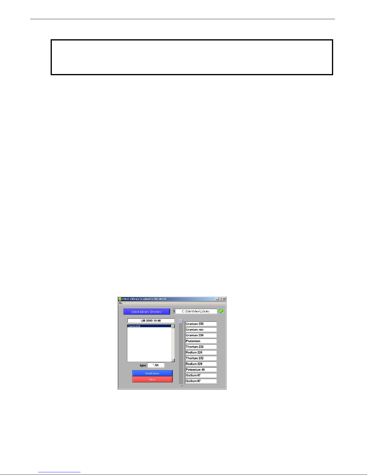
SAIC Exploranium – GR-135 System Manual page: 60
NOTE: When viewing dose/scan data from earlier versions of IdentiView, a checksum error
will be displayed due to a problem with calculating checksum values inside the GR-135
version 1.24 or earlier.
Data Memory
You can download data directly from the GR135 anytime by selecting Download from the Data Memory
menu on the main IdentiView screen. If the GR135 is removed from the DS, you can still save the data
(since it was downloaded to a .temp file) by clicking the “Save GR135 data to file” button on the main
IdentiView screen. Once the data is saved you can erase all the spectra in the data memory of the
GR135 by selecting Erase from the Data Memory menu.
Opening data files
You can open a previously saved data file by clicking the “Open data file for processing” button on the
main screen and selecting a data file from the Open box.
Uploading isotope libraries
The installed LabView software comes with a standard isotope library. You can load this library or other
isotope libraries into your IdentiView software:
1. Click the Upload Library button on the main screen. The Library dialog box appears.
2. Click the Select Library Directory button. The Select a Library Directory dialog appears.
3. Find a library folder and click the Select Cur Dir button.
4. Select the desired library file. The library name, type, directory path, and associated isotopes now
appear in the Library dialog box.
5. Click the Upload Library button to have IdentiView accept and apply the library information.
The isotopes will now appear in the display when you view the search data.
Page 61
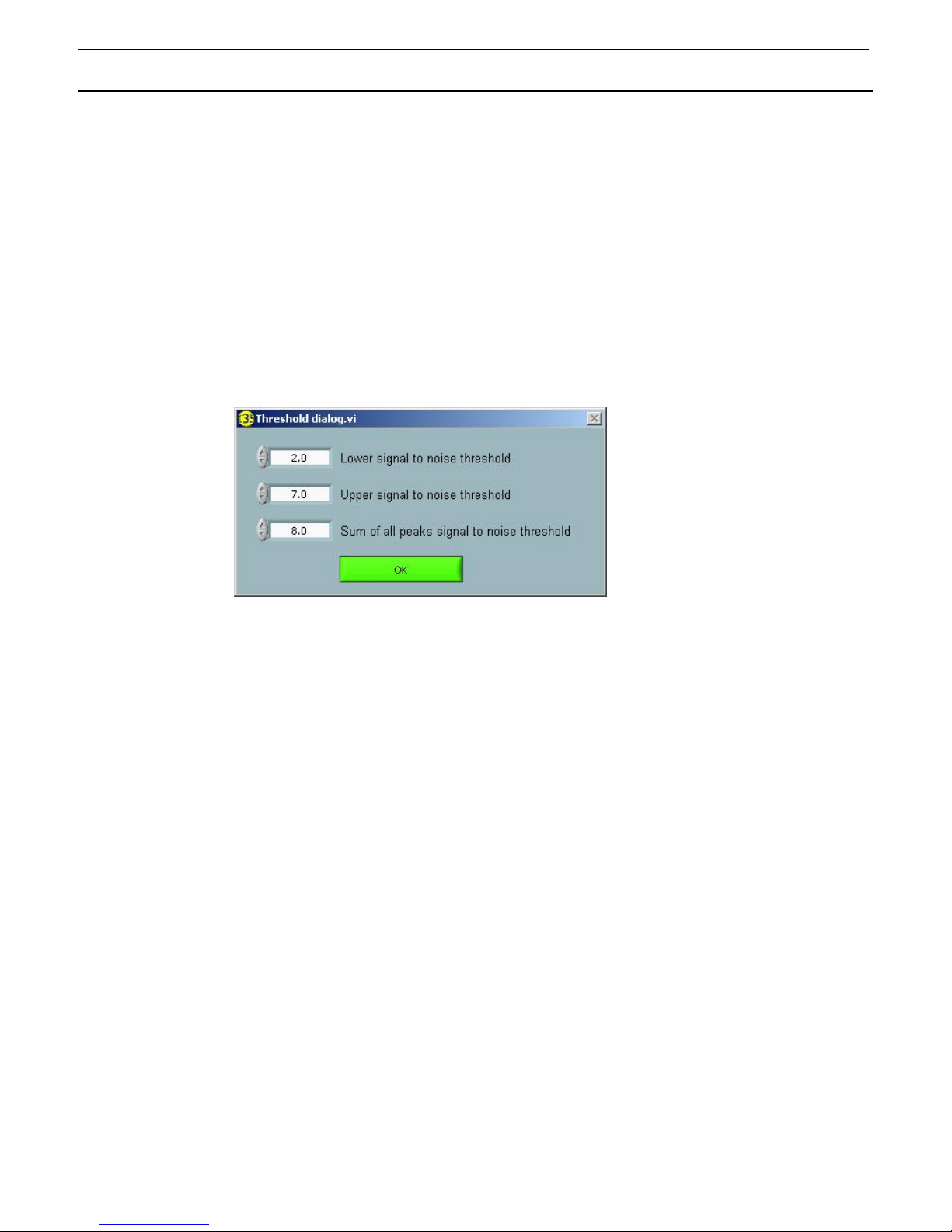
SAIC Exploranium – GR-135 System Manual page: 61
3.3 SETTING IDENTIVIEW OPTIONS
IdentiView lets you do the following tasks through the Options menu on the main IdentiView screen:
• Set the signal to noise thresholds
• Retrieve data from a previous IdentiView version
• Select the time and date format
Setting signal to noise thresholds
You can set the signal to noise thresholds by selecting Threshold Settings from the Options menu. The
following dialog box appears:
Set values for the following thresholds using the up or down arrows:
• Lower signal to
noise threshold
• Upper signal to
noise threshold
• Sum of all peaks
signal to noise
threshold
Retrieving data from a previous IdentiView version.
If you have a data file that was created and saved using a previous version of the IdentiView software,
you can retrieve it using the latest version as follows:
1. Select Advanced from the Options menu.
2. From the submenu, select Open 1v16 file. A dialog box appears.
3. Select the file to be opened.
- This is the level at which peaks are considered to be “real” or significant and
can be used to identify isotopes. Unidentified peaks above this level but
below the upper threshold are shown as a blue line. The default value is 3.0.
- This is the level at which peaks are considered to be significant and can be
used to identify isotopes. Unidentified peaks above this level are shown as a
red line. The default value is 6.0.
- This is a threshold that will reduce the number of false positives by requiring
that for each isotope identified the total sum of all peaks’ signal to noise ratio
is greater than this number. To disable this feature for maximum sensitivity,
change this threshold to 3.0 (the same as the lower threshold). The typical
range would be 4.0 to 9.0.
Page 62
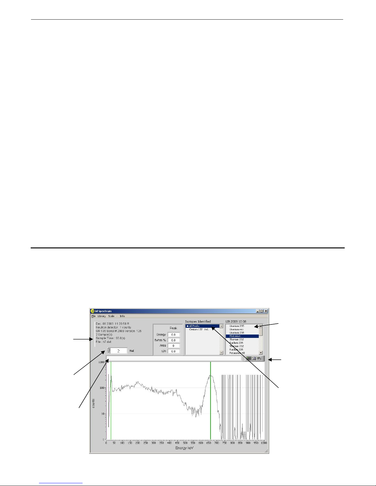
SAIC Exploranium – GR-135 System Manual page: 62
Selecting the time and date format
IdentiView gives you several time and date formats from which to choose. From the Options menu,
select Time and Date, and choose one of the following:
• Show local time
- Displays the local time of day in the View Spectra Data, View Search Data,
and View Dose Data charts. For display purposes only, data and unit still
contain GMT time.
• Show GMT
(UTC) time
- Displays Greenwich Mean Time of day in the View Spectra Data, View Search
Data, and View Dose Data charts. No time zone conversion is done.
• Synchronize on
- Synchronize the time of day to Greenwich Mean Time (UTC). The default is
automatically set every time the unit is placed in the docking station.
• Synchronize off
- Allows you to set the time manually.
• Date format
- Lets you choose one of the following options for displaying the date:
- MMM DD YYYY
- MM DD YYYY
- DD MM YYYY
- YYYY MM DD
3.4 VIEWING SPECTRA DATA
Once the spectra have been down loaded and stored on the PC they can be inspected.
Click the “View Spectra Data” button to see the spectra graphically.
Identifies the GR135 unit, firmware
version, sample
time, and date and
time of the
spectrum. Each
specific has its own
date/time stamp.
Select spectrum #
using up/down
arrows. This box
goes RED when
the last spectrum is
reached.
Optional user text
box where custom
comments can be
entered (for printing
purposes only)
Current library in use.
Graph pallete with
cursor and search
functions.
Active indication (double
click to force All peaks)
Page 63

SAIC Exploranium – GR-135 System Manual page: 63
The main display shows the selected spectrum in LINEAR mode. You can use the “Scale”
button to select LOG if required. The following information is shown:
• The GREEN lines show the peaks that have been identified by the spectral analysis engine
and the “Isotopes Identified” data box names these isotopes.
• The BLUE lines show peaks found but too small to use for accurate analysis.
• The RED lines show peaks that are over the signal to noise threshold but relate to isotopes
that could not be found.
• The dotted vertical PURPLE is the cursor. The mouse can be used to drag this cursor
(position, left-click and hold then drag)
• From the current library (in the upper right corner) you can click on any line and the required
lines for that isotope will appear on the spectral display. This allows you to quickly scan
through the library and compare selected isotopes to the displayed peaks for a more in depth
analysis.
• Any lines that find peaks that match the selection show as GREEN. If there is no match then
they show as RED.
Using isotope libraries and CZT data
The isotope library file that is used to upload to the GR-135 is the same as the one that can be
loaded for analysis. The data will be re-analyzed with the new isotope library. The registry will
remember the last library selected and will always use that library.
CZT data is shown in the same manner. In the event that CZT spectra have been collected the
software recognizes this and changes the labels at the middle-right to define which detector the
spectrum represents.
As explained earlier in the manual, if the system triggers an automatic analysis using the CZT
detector, then the previous recorded spectrum is the NaI spectrum. If, for example, there are 4
spectra in memory then a new NaI spectrum would be #5. However, if the CZT is triggered then
the final display will show “Recorded as spectrum #6”. This means that the CZT spectrum is #6
and therefore its corresponding NaI spectrum is #5.
On the graphic display shown it is very easy to see the differences in these data as the NaI
spectra is very large in amplitude compared to the CZT spectra.
Focusing on portions of the spectra
You can focus on certain portions of the spectra by using the Graph Pallette:
1. Turn off Auto-scaling by clicking the Scale menu and deselecting X Auto Scale and Y Auto Scale.
2. If you don’t see the Graph Pallette, right-click anywhere on the graph, select Visible Items, and
select Graph Pallette from the sub menu. The toolbar appears.
Page 64
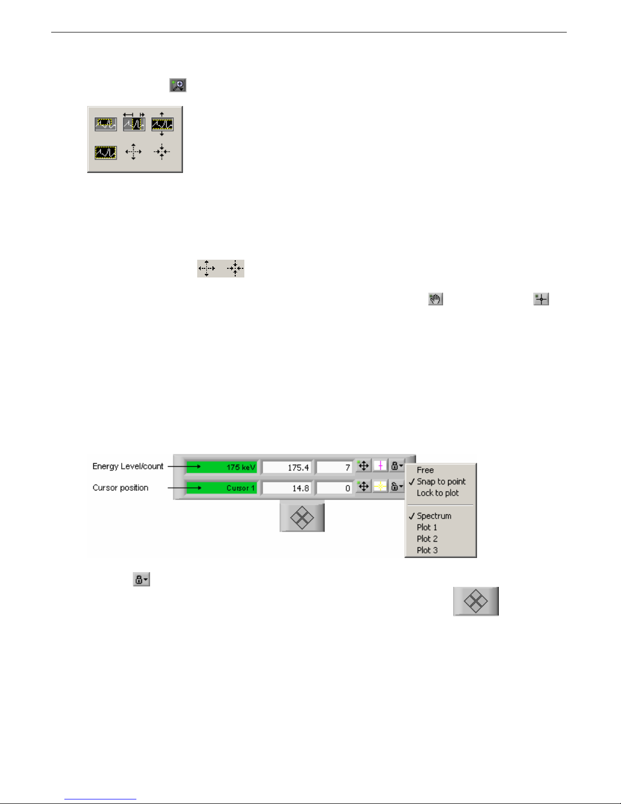
SAIC Exploranium – GR-135 System Manual page: 64
3. Click the Search
icon. The Graph Pallette appears.
4. Select one of the options to let you block off a certain vertical, horizontal, or square portion of
the graph.
5. Drag the cursor across the area of the graph that you want to examine. That area now becomes
the focus. The Counts and Energy scales re-adjust accordingly.
6. Use the zoom options to magnify or reduce the area you are examining.
You can move the graph in any direction with the cursor by first clicking the
icon. Clicking the
icon returns the cursor to its normal state.
Examining the spectra in detail
You can examine on certain portions of the spectra in more detail by using the Cursor Legend:
1. Turn off Auto-scaling by clicking the Scale menu and deselecting X Auto Scale and Y Auto Scale.
2. If you don’t see the Cursor Legend, right-click anywhere on the graph, select Visible Items, and
select Cursor Legend from the sub menu. The Cursor Legend appears.
3. Click the
icon, then select Snap to point.
4. Drag the cursor by the purple line or click the left and right arrows on the
The cursor will now follow the spectra activity lines, displaying the energy level at each point along the
scale. When the cursor moves close to any peak, the details are displayed in the Peak section.
pad.
Page 65
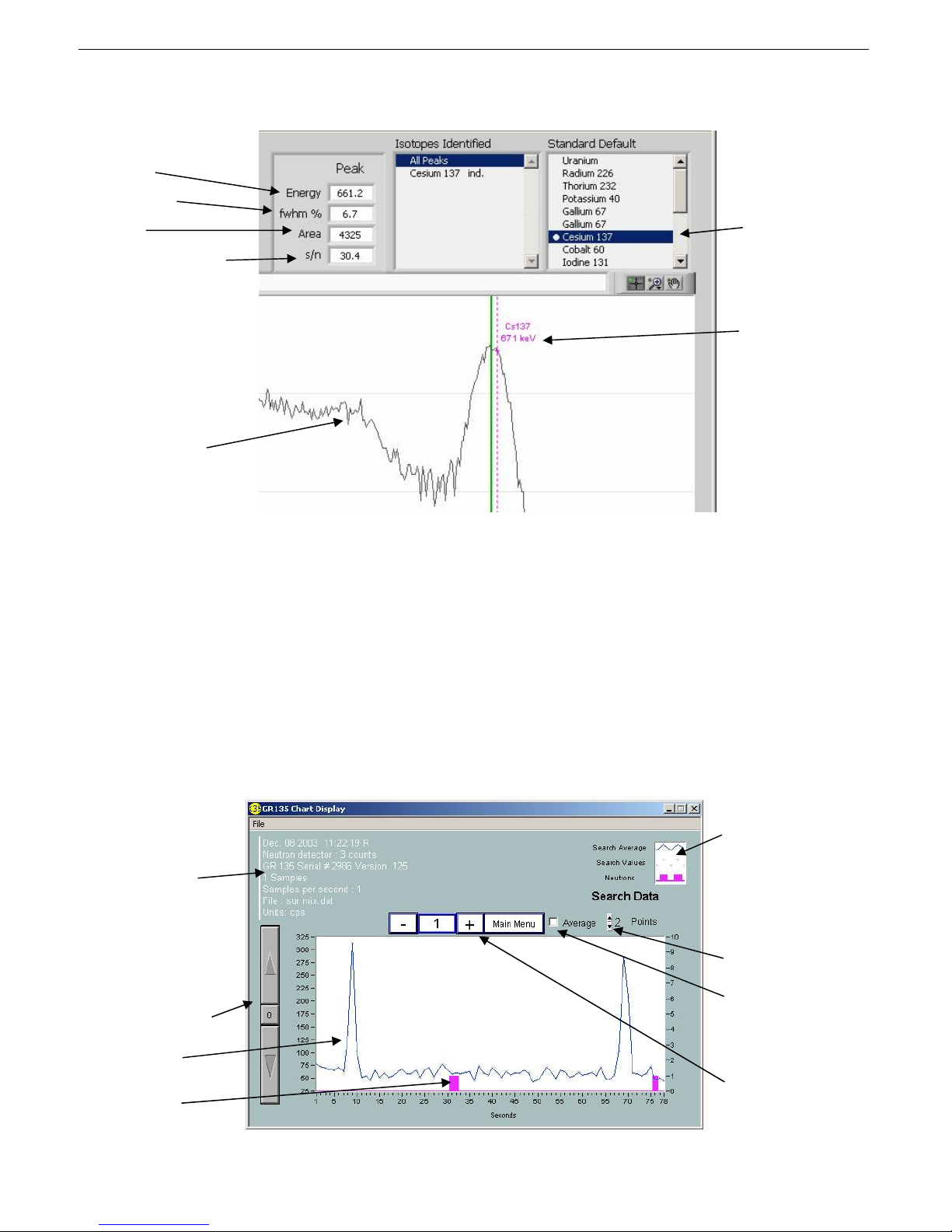
SAIC Exploranium – GR-135 System Manual page: 65
Peak info closest to the
cursor
Resolution
Size
Signal to noise ratio
Compton edge
Active Indicator
Cursor energy
A negative signal to noise ratio indicates that a peak has been found but is likely the result of
backscatter or a Compton edge. Even if the peak is not highlighted with a red, green, or blue indicator,
the peak info will be displayed.
3.5 VIEWING SEARCH DATA
You can views counts per second as a function of time. Click the View Search Data button on the
IdentiView main screen. The Chart display appears.
Identifies the GR135 unit, firmware
version, sample
time, and date and
time of the
spectrum. Each
specific has its own
date/time stamp.
Adjust cps scale
Gamma data
Neutron data
Plot Legend (enabled
from Visible items on
the context menu)
gives you various
styles and options for
displaying the
spectra.
Sets the average for
the number of data
points
Averages the search
data
Select spectrum
number using -/+
buttons.
Page 66
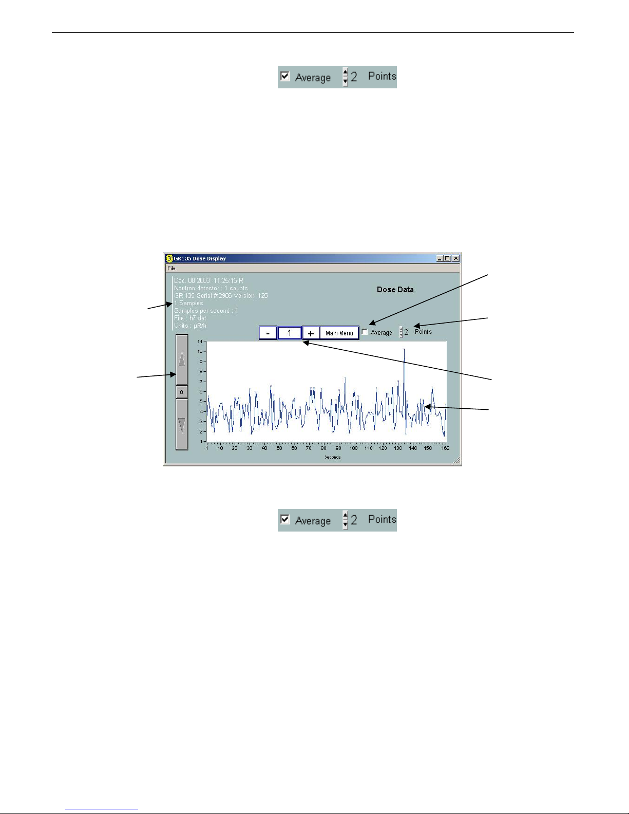
SAIC Exploranium – GR-135 System Manual page: 66
You can use the Average and Points controls
to reduce statistical noise in order
to see a more accurate view of counts and neutron data.
By default, search data is not stored; you have to choose to save search data as part of the setup.
3.6 VIEWING DOSE DATA
Dose data lets you see a replay of how high the actual radiation dose level was for each spectrum. You
can review the dose data history for each spectrum by looking at the chart.
Identifies the GR-135
unit, firmware
version, sample time,
and date and time of
the spectrum. Each
specific has its own
date/time stamp.
Adjust cps scale
Averages the
search data
Sets the average
for the number of
data points
Select file/record
number using -/+
buttons.
Dose data
Dose data is calculated based on the full counts for the spectrum (spectra-weighted dose calculation).
You can use the Average and Points controls
to reduce statistical noise in order
to see a more accurate view of dose data.
By default, dose data is not stored; you have to choose to save search data as part of the setup.
3.7 EXPORTING DATA
From the main display you can choose to export spectra, search, and/or dose data to a separate file.
(The box to the right of each export function shows the number of spectra). The exported data is
reformatted and stored under a similar filename with at .txt extension. These data are Live Time
corrected and stored in an ASCII text format that permits direct loading into programs such as Excel as 1
spectra/column. The spectrum data files can be sent as email attachments for viewing on other
computers that are running the IdentiView program. This is the preferred way to send data for further
evaluation. However, data can also be exported to other programs as a text file.
Page 67
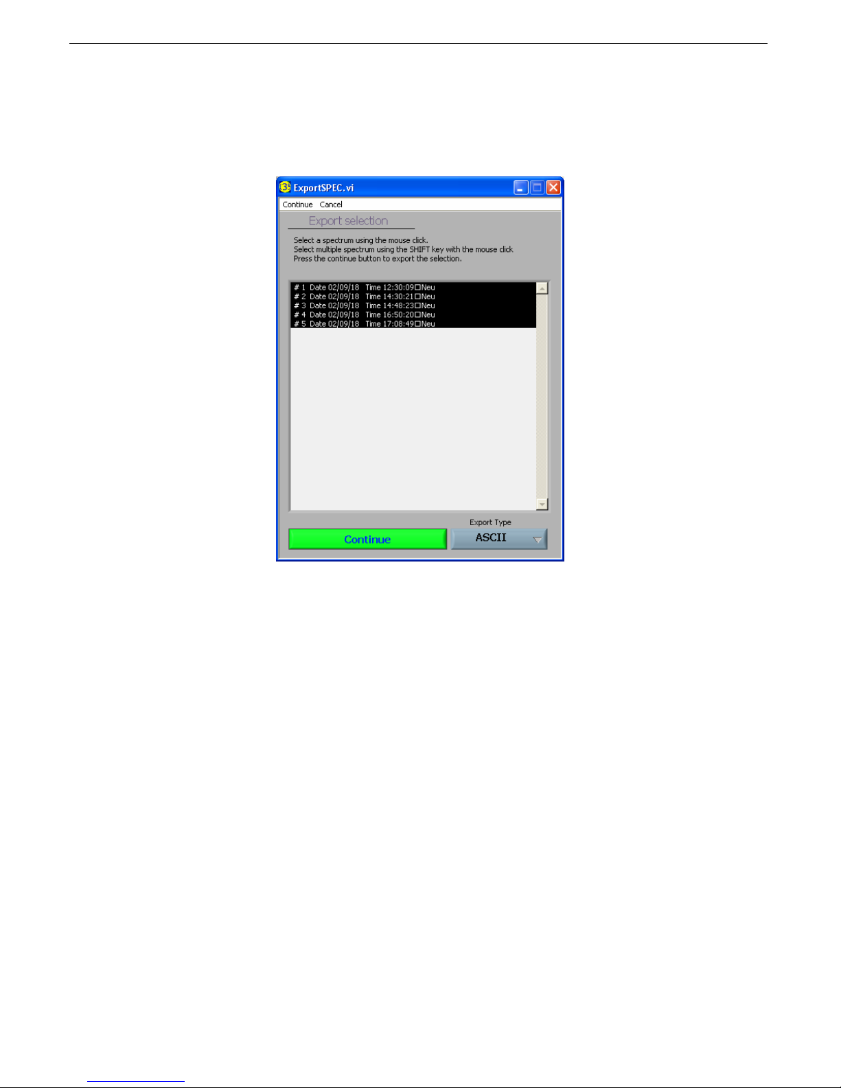
SAIC Exploranium – GR-135 System Manual page: 67
This process is carried out as follows:
- Press the “Export” button and a new display appears:
-
- As the display above shows, the mouse is used to select a single spectrum or SHIFT-click
to select multiple spectra. Note that the date and time of when the spectra was stored is
also displayed, which helps in data selection.
- The button labeled “ASCII” permits ASCII or GBS. GBS data is a standard used by the
IAEA for data analysis. ASCII is text data that can be easily imported into any
spreadsheet.
- Click “Continue” to save the data to any required location. We recommend a *.txt file
extension if ASCII format is selected to make it easier to import into Excel as required.
However, since this will be an ASCII file then the user can use it as required.
- The saved file can then be attached to an email as required and sent to experts for further
analysis.
- Exported dose and scan data are the same (see the following illustration of exported dos e
data).
Page 68
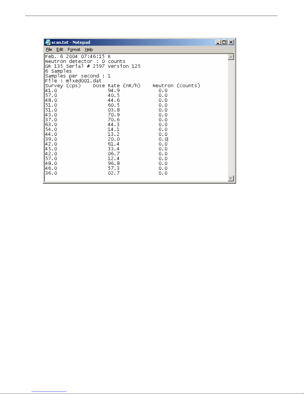
SAIC Exploranium – GR-135 System Manual page: 68
Page 69
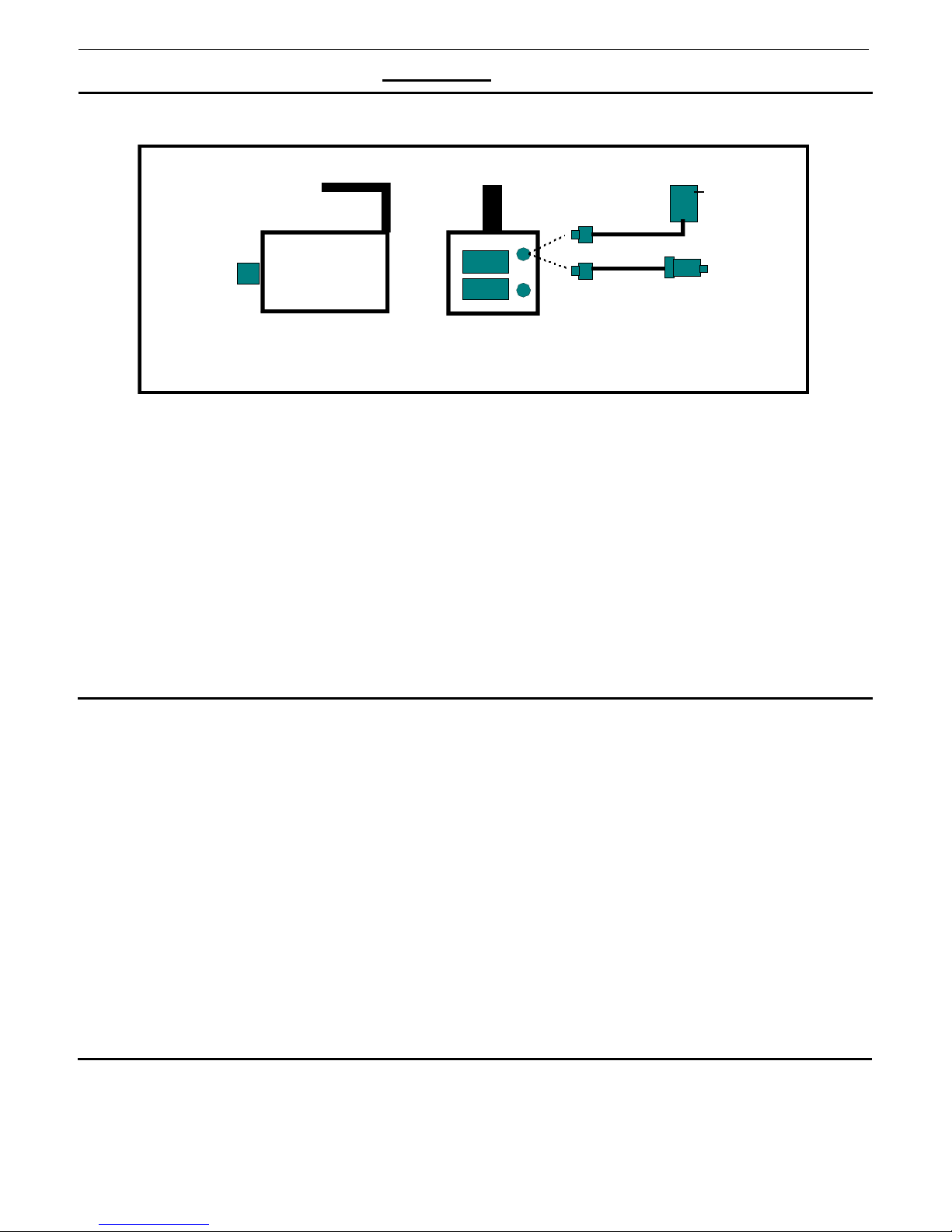
SAIC Exploranium – GR-135 System Manual page: 69
APPENDIX C - OPERATION WITHOUT THE DOCKING-STATION
1. DESCRIPTION
0.25uCi
Cs-137
source
The figure shows the necessary hardware requirements for non-DS operation. Normally the GR135 is supplied with a DOCKING-STATION (DS) but additional accessories are available. For nonDS use, the user needs a TEST SOURCE and a POWER CABLE, these optional items are:
a) TEST SOURCE
b) POWER CABLES
- PN 92309-3 – 115VAC (Australia) – 12V DC assembly
- PN 92309-4 – Universal 115/220VAC (North America) – 12V DC assembly
- PN 87387-1 – Cigarette lighter plug - 12V DC assembly
2. STABILIZATION
Stabilizing the GR135 outside the DS depends on the MODE of operation.
a) MANUAL MODE
From the MAIN MENU select STABILIZE then proceed as described in Section 7.3 except in
this case the source is held against the face of the unit rather than sitting the unit in the DS.
b) AUTOMATIC MODE
In this case it is necessary to let the unit think it is in the DS as the Automatic mode functions
are optimized for this mode of operation. This is easily done as follows:
- place the Test Source against the face of the instrument
- plug in one of the sources of external power shown above in the figure
- as long as external power is supplied the unit will continue to automatically stabilize as
described in Appendix A
NOTE – if the Test Source is removed an error message will appear on the display
3. BATTERY CHARGING
The battery charger is integrated into the GR-135 electronics so the external “battery charging” is
really supplying 12VDC to the unit to charge the two “D” cell NiCd batteries in the GR-135
without removing them from the instrument.
GR-135
Rear view with battery
door re m ove d
- PN 87046-1 – 0.25uCi Cs-137 Test Source
- PN 92309-1 – 220VAC (Europe) – 12V DC assembly
- PN 92309-2 – 220VAC (UK) – 12V DC assembly
115/220
AC
12V DC
Page 70

SAIC Exploranium – GR-135 System Manual page: 70
This 12V DC input can be supplied from an external AC:DC power source or via a special cable
that can be connected directly to the lighter socket of a vehicle as shown above. This 12V input
is also used to power the unit for extended sampling when normal battery life may be
insufficient. Approximately 8 to 10 hours of charging is required to charge a fully discharged set
of batteries.
NOTE
APPLYING EXTERNAL POWER TO THE GR135 OPERATES THE UNIT BUT
ALSO CHARGES THE BATTERIES. THE BATTERY CHARGERS PROVIDED
WITH THE GR-135 IS FOR USE WITH NICD “D” CELL BATTERIES
ONLY. OPERATING THE CHARGER WHILE ALKALINE
BATTERIES ARE
IN THE UNIT MAY CAUSE BATTERY LEAKAGE AND MAY SERIOUSLY
DAMAGE THE GR-135. EXPLORANIUM IS NOT RESPONSIBLE FOR ANY
DAMAGE CAUSED BY IMPROPER BATTERY CHARGER OPERATION.
Page 71
SAIC Exploranium – GR-135 System Manual page: 71
APPENDIX D - NUCLIDE LIBRARIES
There are 2 levels of nuclide library data in the GR-135 – SNM nuclides and other nuclides.
SNM NUCLIDES - Since SNM materials are an
extremely complex analysis requirement this
capability is HARD CODED into the system and the
user has no access to remove or change these
items. Discuss this with Exploranium if this is an
issue. The items coded are
and U-235
.
Pu-239, U-233
OTHER NUCLIDES – these items are stored in a
special memory location and the user has access
to add, change, delete or modify these items using
the new IdentiView software (Appendix B).
However the GR-135 has a very complex analysis
capability so any library changes should be
discussed with Exploranium. If required a special
library can be developed and emailed to the user
who can then use IdentiView to upload this
library into the system.
Currently Exploranium has no plans to permit
users to modify their own libraries as library
development is so complex that modifications can
easily unbalance the analysis capability of the
system and significantly degrade performance.
However we will readily work with users at no
charge to develop an appropriate library to fulfill
their special requirements
Note that a future software release will permit 5
libraries to be stored in memory and the user can
select the appropriate library required for special
functions as required.
The current list of nuclides in the library are :
Library names
S=Standard, M=Medical, I=Industrial, W=Waste, U=User
Labels in columns
I=labeled as Industrial. M=Medical, S=SNM, N=NORM
Name
Americium-241 I I I
Ba-133 Barium-133 I
Bi-207 Bismuth-207
Cf-252 Californium-252
Cd-109 Cadmium-109
Ce-139 Cerium-139
Co-57 Cobalt-57 I M I M
Co-58 Cobalt-58
Co-60 Cobalt-60 I I I
Cr-51 Chromium-51 M
Cs-137 Cesium-137 I I I I
DEP-U Depleted-U
Eu-152 Europium-152
Eu-154 Europium-154
F-18 Fluorine-18
Fe-59 Iron-59
Ga-67 Gallium-67 M M M
I-123 Iodine-123 M M
I-125 Iodine-125
I-129 Iodine-129
I-131 Iodine-131 M M M
In-111 Indium-111 M M M
Ir-192 Iridium-192 I I I I
K-40 Potassium-40 N N N
Kr-85 Krypton-85
Mn-54 Manganese-54
Mo-99 Moly-99
Na-22 Sodium-22
Na-24 Sodium-24
Np-237 Neptunium-237 S
Pd-103 Palladium-103 M M
Pu-239 Plutonium-239 S
Ra-226 Radium-226 N N N
Se-75 Selinium-75
Sm-153 Samarium-153
Sn-113 Tin-113 M M
Sr-85 Strontium-85 M M
Tc-99m Technet-99m M M M
Th-232 Thorium-232 N N N
Tl-201 Thallium-201 M M M
U-233 Uranium-233 S
U-235 Uranium-235 S
U238/5 Uranium-235/8 N N
Xe-133 Xenon-133 M
Y-88 Yttrium-88
Y-90m Yttrium-90m
Label S M I W U
Page 72

SAIC Exploranium – GR-135 System Manual page: 72
APPENDIX F - DOCKING STATION DETAILS
1. GENERAL
The Docking Station (DS) is specially designed for ease-of-use. The DS features are :
- 4 spring-loaded electrical contacts for connection to the base of the GR135
- Integrated 0.25uCi Cesium-137 source – BELOW CONTROL LIMITS WORLD WIDE
- 3 LEDs on the front panel showing system status
- 2 connectors on the rear for external DC and RS232 connection
2. LEDs
The 3 LEDs operation is as follows :
ERROR
RED
OFF ON ON CHARGING
OFF ON FLASH END OF CHARGING
OFF ON OFF ALKALINE batteries in 135
FLASH ON OFF DOCK EMPTY
OFF FLASH OFF ERROR #1
ON ON ON ERROR #2
FLASH ON FLASH ERROR #3
OFF OFF OFF NO INPUT POWER
Error #1 – Low Input Voltage – check AC adapter or input AC line
Error #2 – High current load – Bad GR135, Maintenance required
Error #3 – Power disconnected – short circuit inside GR135, Maintenance required
POWER
GREEN
CHARGE
YELLOW
DS STATUS
or Battery fully charged
Page 73

SAIC Exploranium – GR-135 System Manual page: 73
APPENDIX G – RECOMMENDED PARAMETERS
SETUP MENU PARAMETER DEFAULT Selection
SEARCH
SAMPLE TIME 1 1-10, 20-60 secs
CHART RANGE AUTO AUTO, 64, 128, 256, 512, 1K, 2K, 4K, 8K, 16K, 32K,
AUDIO METER AUTO 50, 100, 150, 200, 250cps
ALARM LEVEL OFF OFF, 100, 200, 250, 300, 350, 400, 450, 500, 600, 700,
SCAN WINDOW TOT TOT, ROI1, ROI2, ROI3
AVERAGING 3P OFF, 3P , 5P, 10P
STABILIZE
STAB VALID 24H OFF, 12H, 24H
IDENTIFY
DETECTOR DETECTOR AUTO NaI, CZT, AUTO
NaI MEAS TIME 55 10-50, 55, 60-100, 200-600, 1200, 1800, 3600, 5400secs
MEAS MODE CLOCK LIVE, CLOCK, REP.
ADC 1024 1024
AUDIO ON ON, OFF
GAIN CORR ON ON, OFF
CZT MEAS TIME 300 10-100, 200-600, 1200, 1800, 3600, 5400secs
MEAS MODE CLOCK LIVE, CLOCK
ADC 1024 1024
AUDIO ON ON, OFF
CZT OFFSET read -10 ….. +10
NEUTRON N SUMMING 3P OFF, 3P, 5P, 10P
ALARM LEVEL 3 OFF, 1,2,3, 4, 5, 6, 7, 8, 9, 10, 20, 50, 100
SAMPLE TIME 1 1, 2, 3, 4, 5, 6, 7, 8, 9, 10, 15, 20, 50, 100
N IDENT THR. 5 OFF, 1, 2, 3, 4, 5, 6, 7, 8, 9, 10, 20, 50, 100
N UNITS cps cps, uSv/h
DOSE
SAMPLE TIME 1 1-10, 20-60secs
AVERAGING 3P OFF, 3P , 5P, 10P
CORRECTION 100 85, 90, 95…..120%
ALARM LEVEL 2000u OFF, 10, 20, 50, 100, 200, 500, 1000, 2000, 4000, 5000,
ROIs
ROI#2 210-230 1–1024 to 1-1024 (Cs137)
ROI#3 320-470 1–1024 to 1-1024 (Co60)
MISC
BATTERY NICD NICD, ALK
BACK LIGHT OFF OFF, ON, 5S, 10, 30S, 60S
ACTIVE LIBR. STAND STAND, MEDIC, INDUST, WASTE, USER
OUTPUT TO OFF OFF, MEM, PC
64Kcps
1K, 2K, 5K, 9Kcps
CZT FINE GAIN read Set as required 0-1024 (Gain steps)
PILEUP ON ON, OFF
PEAK LIMIT 30 20, 25, 30, 35, 40, 45, 50 (SD units)
AUTO NI LIM. 25 10, 15, 20, 25, 30, 35, 40, 45, 50 (%)
MEAS UNIT
ROI#1 15-30 1–1024 to 1-1024 (Am241)
LANGUAGE ENG ENG, DEU, FRA, SPA, NEW
R
R, SV, GY
9000 (LINKED TO Units)
Page 74

SAIC Exploranium – GR-135 System Manual page: 74
APPENDIX H – WIPE TEST (OPTIONAL)
If requested by the user, before the GR135 is shipped
, a
special capability is enabled that permits a WIPE TEST function.
This function permits the GR135 to provide an semi-automatic
measure of removable contamination. This function only
operates in the AUTO mode.
In SETUP/IDENTIFY/DETECTOR a new parameter WIPE TH
may be set – the parameter is set 1-10 in SD units with a default
of 3.
Function is as follows:
1. If the portal system alarms then the GR135 is used to find the location of the maximum radiation
on the side of the vehicle
2. The user normally then carries out IDENTIFY to determine the isotopic content of the radiation as
described earlier in the manual
3. Once located and identified, then the vehicle must be tested for REMOVABLE CONTAMINATION.
The user takes a standard WIPE TEST sample cloth and carefully wipes a 10cm
area of the vehicle side where the maximum radiation has been detected. This sample material
is then placed in a plastic bag.
4. Press ENTER until the display shows the SEARCH mode. The bottom of the display shows
“UP=WIPE ENTER=IDENTIFY”
5. Click UP (for WIPE). The display shows the message “BACKGROUND NEEDED – MOVE
AWAY FROM VEHICLE THEN PRESS ENTER”
6. Move the GR135 at least 10ft away from any vehicle in the SEARCH mode
bag at least 3 ft away from the GR135 and check that the local Dose Rate where the test will be
carried out is below
10uR/h –- then press ENTER. Higher background will negatively affect
sensitivity of the measurement.
a. If the local Background is above 20uR/h the display will show the message “DOSE RATE
TOO HIGH – MOVE TO LOWER BACKGROUND”. The user must find an area where
the background is lower, or use a shielded compartment to facilitate the measurement.
7. The display will start the IDENTIFY screen for the preset sample period to get a background
sample
8. The display then shows “PLACE WIPE SAMPLE AT DETECTOR FACE THEN PRESS ENTER”
9. Place the plastic bag contain the sample as indicated and press ENTER
10. The display will start the IDENTIFY screen for the preset sample period
11. At the end of this time period the system computes the Contamination Level and compares it to a
preset threshold.
12. If NO CONTAMINATION is detected - at the end of sample the display will show “WIPE TEST
CONTAMINATION IS BELOW ALARM LEVEL”
IDENTIFY
DETECTOR
PILEUP
PEAK LIMIT
NON ID THR
WIPE TH
2
area around the
, keep the test sample
AUTO
ON
30
25
3
Page 75

SAIC Exploranium – GR-135 System Manual page: 75
13. User can now press ENTER and return to the normal SEARCH mode
14. If CONTAMINATION is detected - at the end of sample the display will show “WIPE TEST
CONTAMINATION ABOVE ALARM LEVEL – LEVEL = 55”.
In this case removable contamination has been detected so the
GR135 must be thoroughly cleaned to remove any potential
contamination before further use.
15. HIGH DOSE RATE
The above process works correctly as long as the local Radiation background Dose Rate is below
20uR/h. To prevent this being an issue the system will give a special warning as follows:
The process is:
1. Press ENTER until the display shows the SEARCH mode. The bottom of the display shows
“UP=WIPE ENTER=IDENTIFY”
2. Click UP (for WIPE). The display shows the message “BACKGROUND NEEDED –
MOVE AWAY FROM VEHICLE THEN PRESS ENTER”
3. Move the GR135 at least 10ft away from any vehicle then press ENTER
4. At this time if the local Background is above 20uR/h the display will show the message
“DOSE RATE TOO HIGH – MOVE TO LOWER BACKGROUND”. The user must move
to an area where the background is lower.
5. Recommended method is to press ENTER a few times to move back to the SEARCH mode
and move until the GR135 shows that the Dose Rate is below 10uR/h – then start the test
again with UP from the SEARCH menu
Page 76
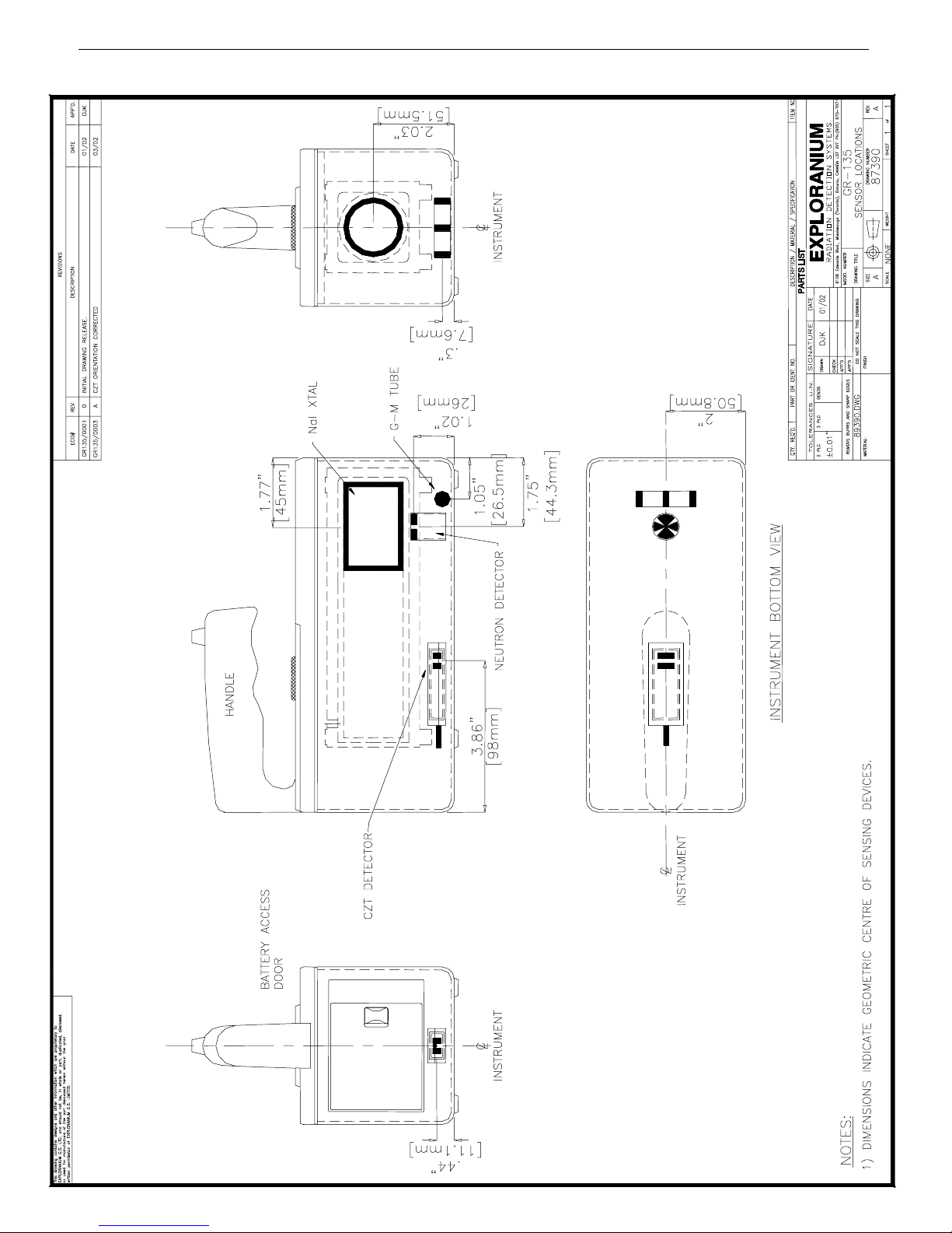
SAIC Exploranium – GR-135 System Manual page: 76
APPENDIX J – SENSOR LOCATIONS
Page 77
SAIC Exploranium – GR-135 System Manual page: 77
APPENDIX X – WARRANTY
EXPLORANIUM WARRANTY
Exploranium warrants the GR-135 Identifier to be free of defects in material and
workmanship for a period of one year from the date of purchase. The warranty does
not cover consumables or damage caused by improper use or unauthorized repairs.
To make a warranty claim, the product must be returned, freight prepaid, to SAIC
Exploranium's factory in Mississauga, Canada. Exploranium will repair or replace
the product, at its discretion, and return the product, freight prepaid.
Ship to: SAIC EXPLORANIUM
6108 Edwards Blvd.
Mississauga, Ontario L5T 2V7 Canada
Attn: Service Department
Phone: 905 670 7071
Fax: 905 670 7072
Page 78

SAIC Exploranium – GR-135 System Manual page: 78
APPENDIX Y – MANUAL CHANGES
Updated for Identiview software version 7.6 – Feb 2004
Page 79

SAIC Exploranium – GR-135 System Manual page: 79
APPENDIX Z - DOCKING-STATION TEST SOURCE SPECS
49 CFR Ch.1 (10-1-01 Edition)
(extraction)
§173.422 Additional requirements for excepted packages containing Class 7
(radioactive) materials.
(a) Except for materials subject to the shipping paper requirements of subpart C of part 172 of
this subchapter, excepted packages prepared for shipment under the provisions of §173.421, §173.424,
§173.426, or §173.428 must be certified as being acceptable for transportation by having a notice
enclosed in or on the package, included with the packing list, or otherwise forwarded with the package.
This notice must include the name of the consignor or consignee and one of the following statements, as
appropriate:
§173.424 Excepted packages for radioactive instruments and articles.
A radioactive instrument or article and its packaging is excepted from the specification packaging,
shipping paper and certification, marking and labeling requirements of this subchapter and requirements
of this subpart, if:
(a) Each package meets the general design requirements of §173.410;
(b) The activity of the instrument or article does not exceed the relevant limit listed in table 7 in
§173.425;
(c) The total activity per package does not exceed the relevant limit listed in table 7 in
§173.425;
(d) The radiation level at 10 cm (4 in) from any point on the external surface of any unpackaged
instrument or article does not exceed 0.1 mSv/hour (10mrem/hour);
(e) The radiation level at any point on the external surface of a package bearing the article or
instrument does not exceed 0.005 mSv./hour (0.5 mrem/hour), or, for exclusive use
domestic shipments, 0.02 mSv (2 mrem/hour);
(f) The nonfixed (removable) radioactive surface contamination on the external surface of the
package does not exceed the limits specified in §173.443(a);
(g) Except as provided in §173.426, the package does not contain more than 15 grams of
uranium-235; and
(h) The package is otherwise prepared for shipment as specified in §173.422.
Page 80

SAIC Exploranium – GR-135 System Manual page: 80
SAFE HANDLING FOR CHECK SOURCES
Docking station:
• Licensing Requirements: Radioactive material contained in this device is exempt from USNRC
or US Agreement State licensing requirements.
• Safe Handling: Although quantities of radioactive material contained in these products are
extremely small, the basic radiation protection principles of time, distance and shielding should
be practiced as effective methods for minimizing exposure.
• Use: These devices should only be used as a method for verifying response of radiation
measuring devices, and are to be used in accordance with manufacture’s instructions.
• Storage: All devices containing radioactive material should be securely stored when not in use.
• Disposal: Different countries may have other regulations with respect to source disposal. The
customer is advised to check local regulations and dispose the source accordingly.
External check sources
• Licensing Requirements: Radioactive material contained in these sources is exempt from
USNRC or US Agreement State licensing requirements.
• Safe Handling: Although quantities of radioactive material contained in these products are
extremely small, the basic radiation protection principles of time, distance and shielding should
be practiced as effective methods for minimizing exposure.
• Use: These devices should only be used as a method for verifying response of radiation
measuring devices, and are to be used in accordance with manufacture’s instructions. These
sources are not for human use, introduction into foods, beverages, cosmetics, drugs or
medicines, or into products manufactured for commercial distribution. Exempt quantities should
not be combined to increase the source activity.
• Storage: All radioactive material should be securely stored when not in use.
• Disposal: Different countries may have other regulations with respect to source disposal. The
customer is advised to check local regulations and dispose the source accordingly.
 Loading...