

Explay S5200BP Service Manual
Customer Service Service Manual
Under control
BDEC-V1.0
Prepared:
Verified:
Approved:
D a t e :22th4, 2014
SERVICE MANUAL
1 / 40

Customer Service Service Manual
CONTENTS
Content
1. Brief Introduction….……………………………………………………………………………….….3
2. Tools……………………………………………………………………………………………………..5
3. Assemble & Dissemble
Dissembly..................…………………………………………………………………………...6~11
Assembly………………………………………………………………………………………...12~17
4. Picture of main board
A&B side of PCBA .…………….…………………………………………………….…………..18
A&B of PCBA Layout………….….………….…………………………….………………….…....19
5. System Block Chart…………………………………………………………………………………...20
6. Unit Circuit Map ..….........................................................................................................21~27
CAUTIONS
Please refer to the phone’s user’s guide for instructions relating to operation, care, and maintenance, which include
important safety information.
Servicing and alignment must be undertaken by qualified personnel only.
Ensure all work is carried out at an anti-static workstation and that an anti-static wrist strap is worn.
Use only approved components as specified in the parts list.
Ensure all components, modules, screws, and insulators are correctly re-fitted after servicing and alignment
Ensure all cables and wires are repositioned correctly
Electrostatic discharge can easily damage the sensitive components of electronic products. Therefore, every service
supplier must observe the precautions which mentioned above.
2 / 40
Customer Service Service Manual
CHAPTER1 INTRODUCTION
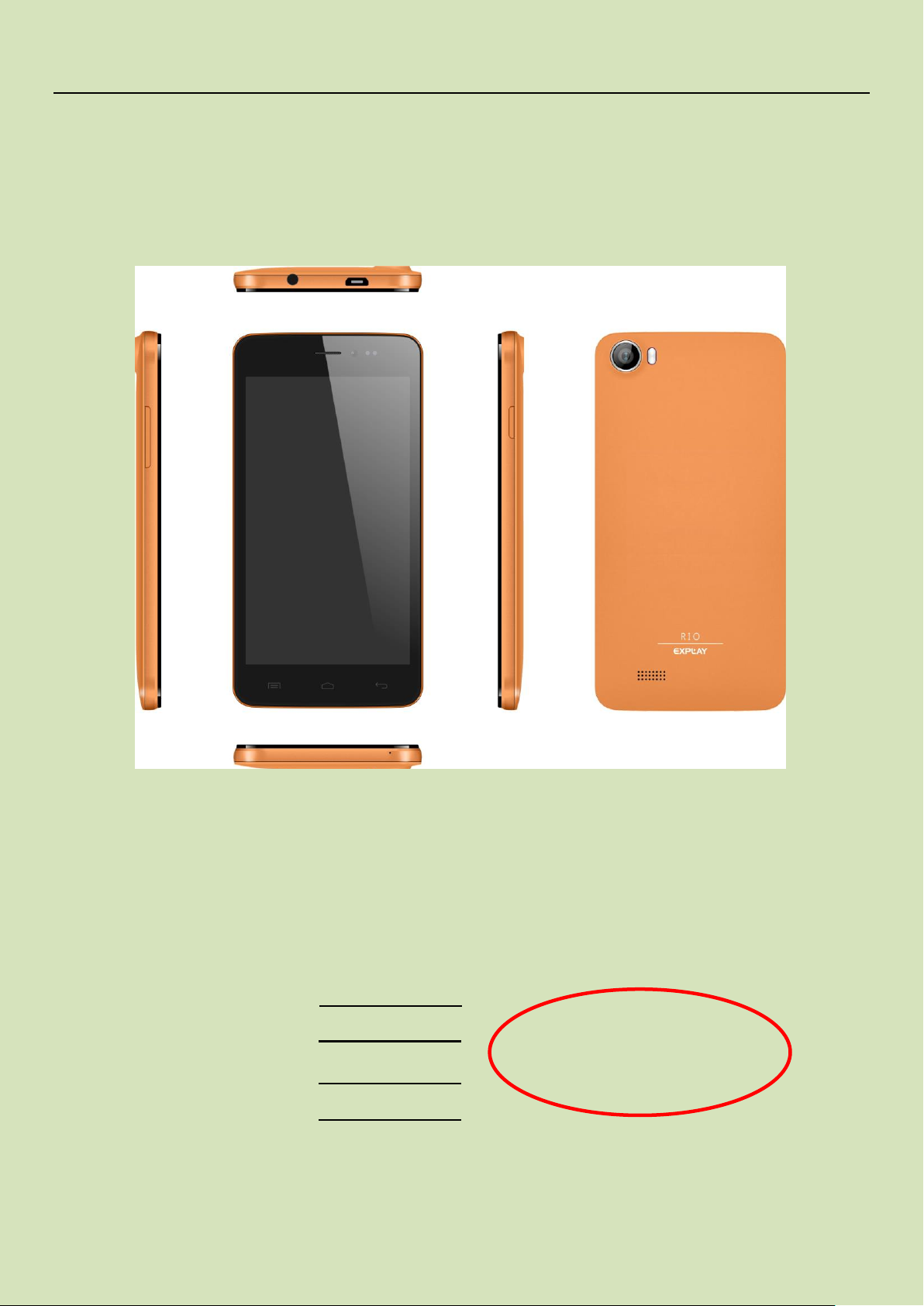
5.0" TN FWVGA Smart phone
G+F TP
MT6572+Android 4.2+2M FF Camera
512MB+512MB
1800mah Battery
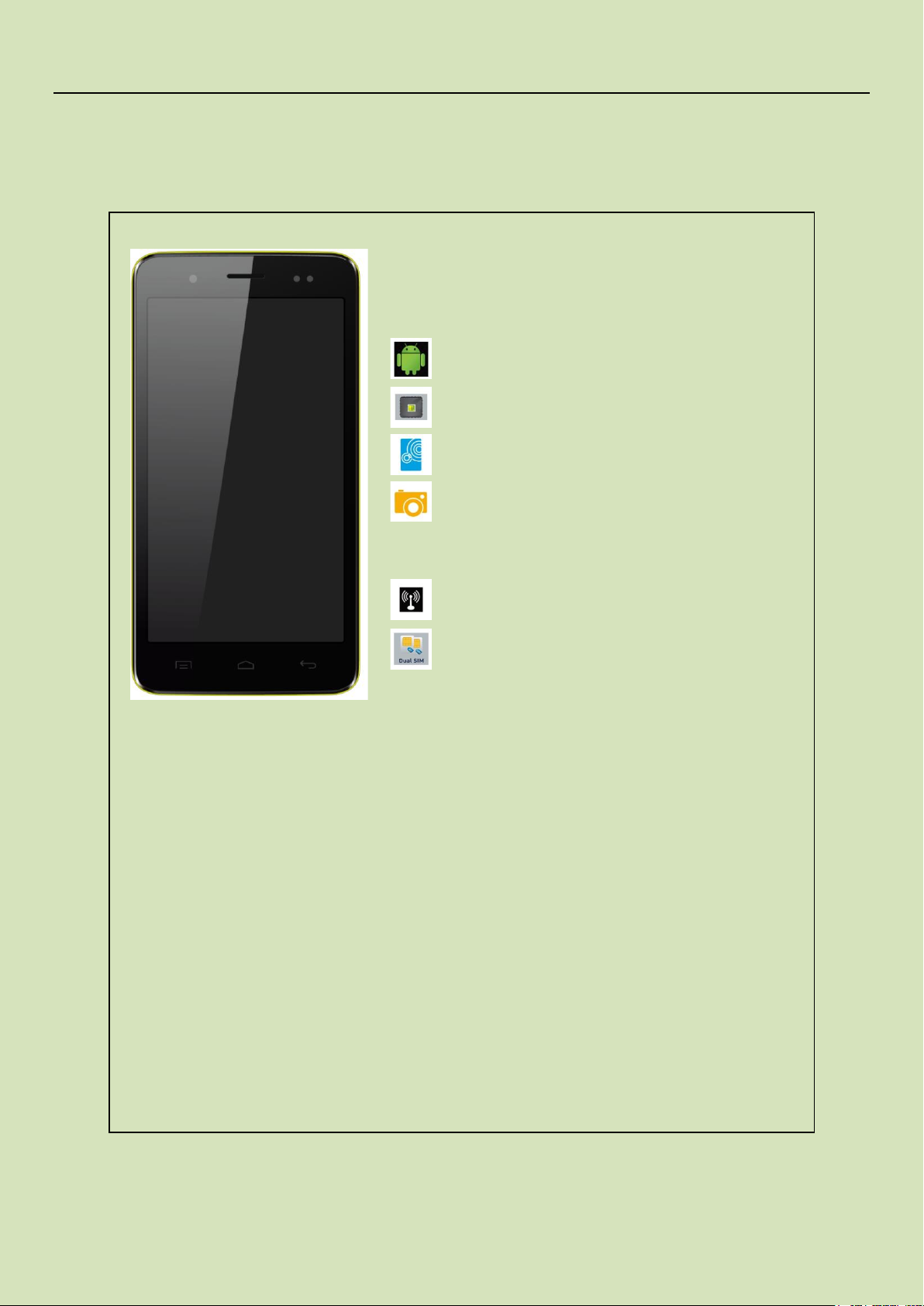
Main Function
Dual Card Full Touch Smartphone
Android 4.2
CPU MT 6572 (1.3GHz Dual core)
5 " FWVGA480*854
Camera:Back camera 2 FF Mega, Front camera
0.3 Mega
WIFI: 802.11n, 802.11g, 802.11b
Dual SIM
3 / 40
Customer Service Service Manual
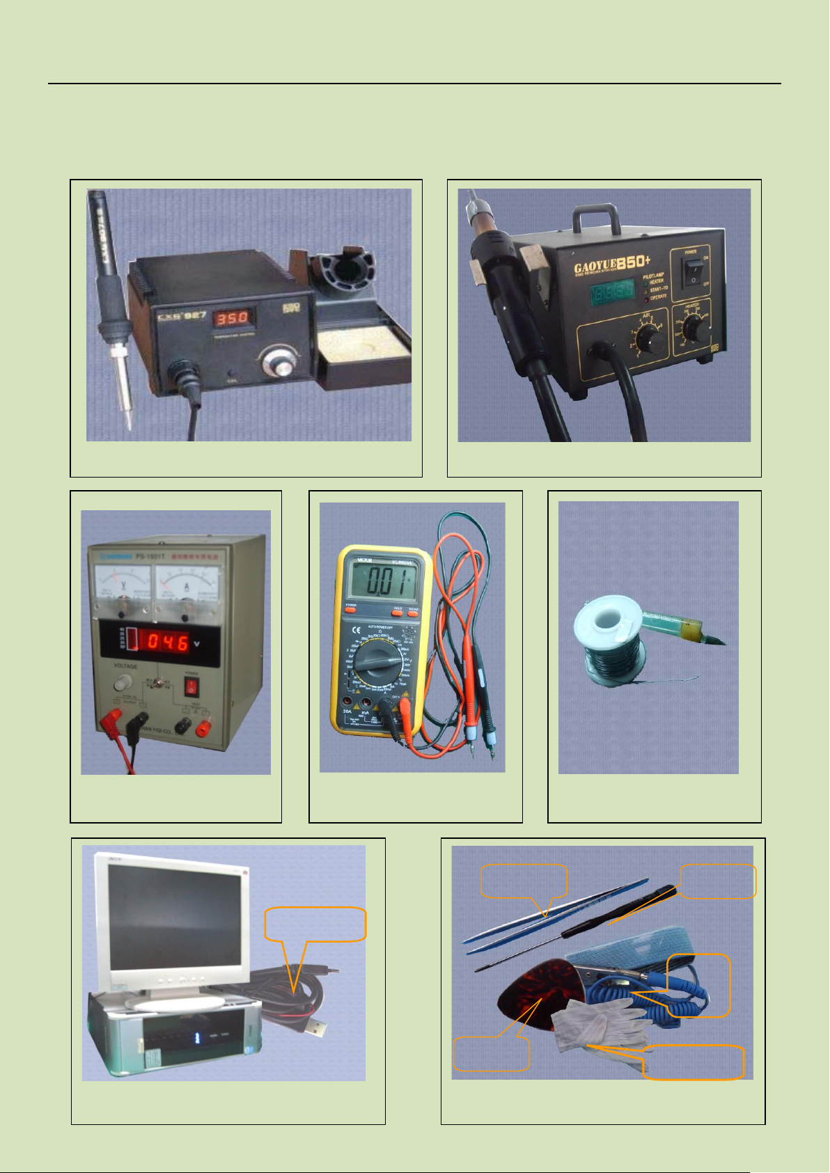
Voltage regulator
Multimeter
Iron
Hot air gun
Solder wire, soldering paste
Computer and software download cable
Metal tweezers, Screw driveretc
Pick
Driver
Tweezers
Wrist
groun
Antistatic
SW
CHAPTER 2、SERVICE TOOLS
4 / 40
Customer Service Service Manual
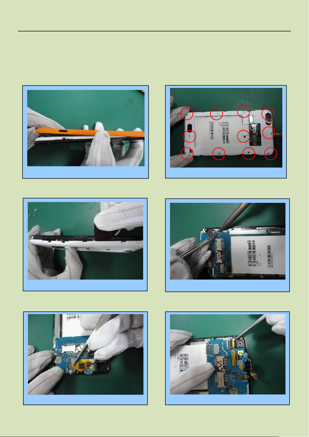
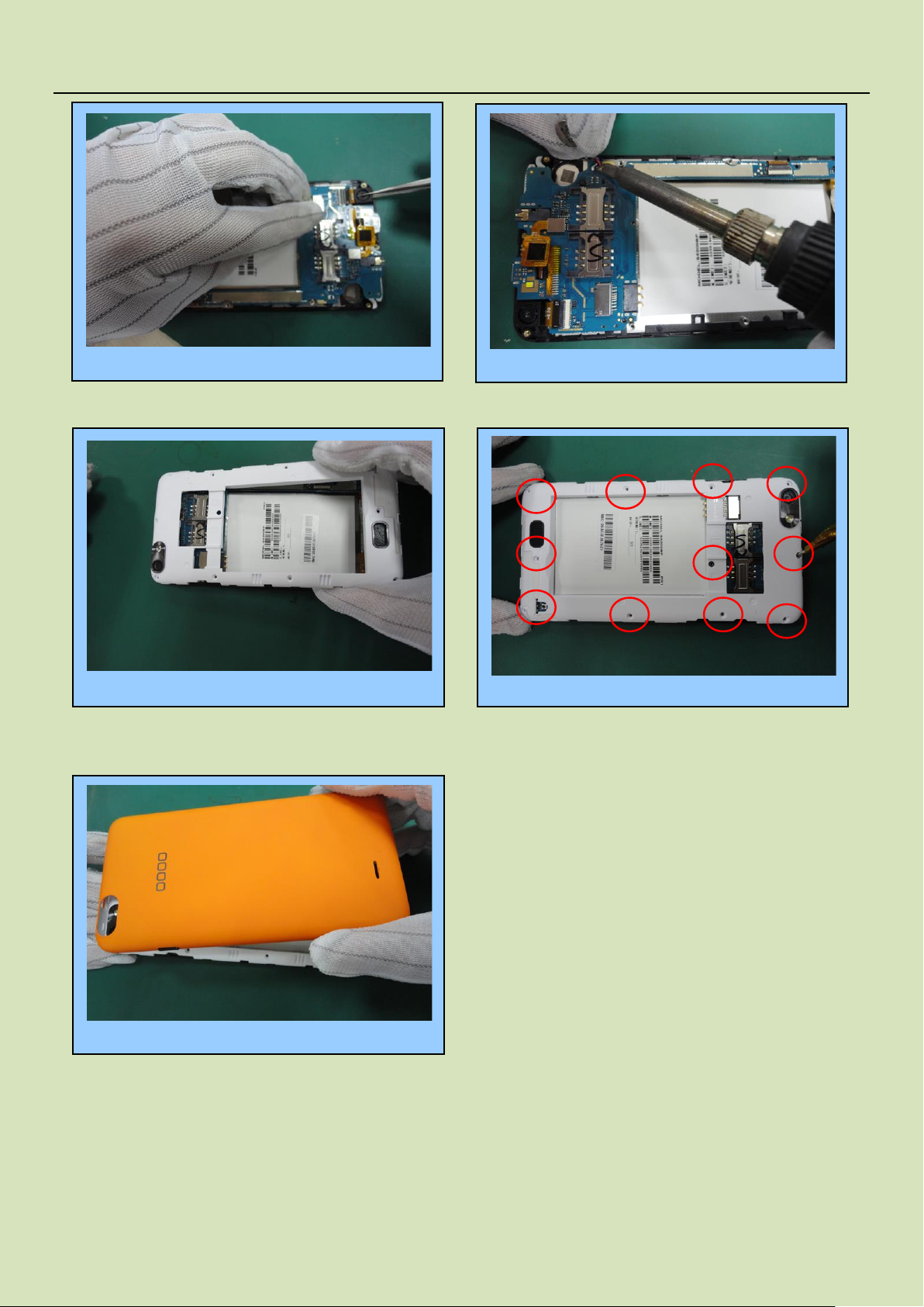
Remove the Battery cover…….……..………………... 1
Unfasten the 11 screws…….…………..…2
Remove the vibrator………………………4
Remove the TP FPC…..………...………..5
Remove the back cover….……………..………..3
Take out the camera..…………….……... 6
CHAPTER 3、DISASSEMBLY AND ASSEMBLY
3.1 DISASSEMBLY
5 / 40
Customer Service Service Manual
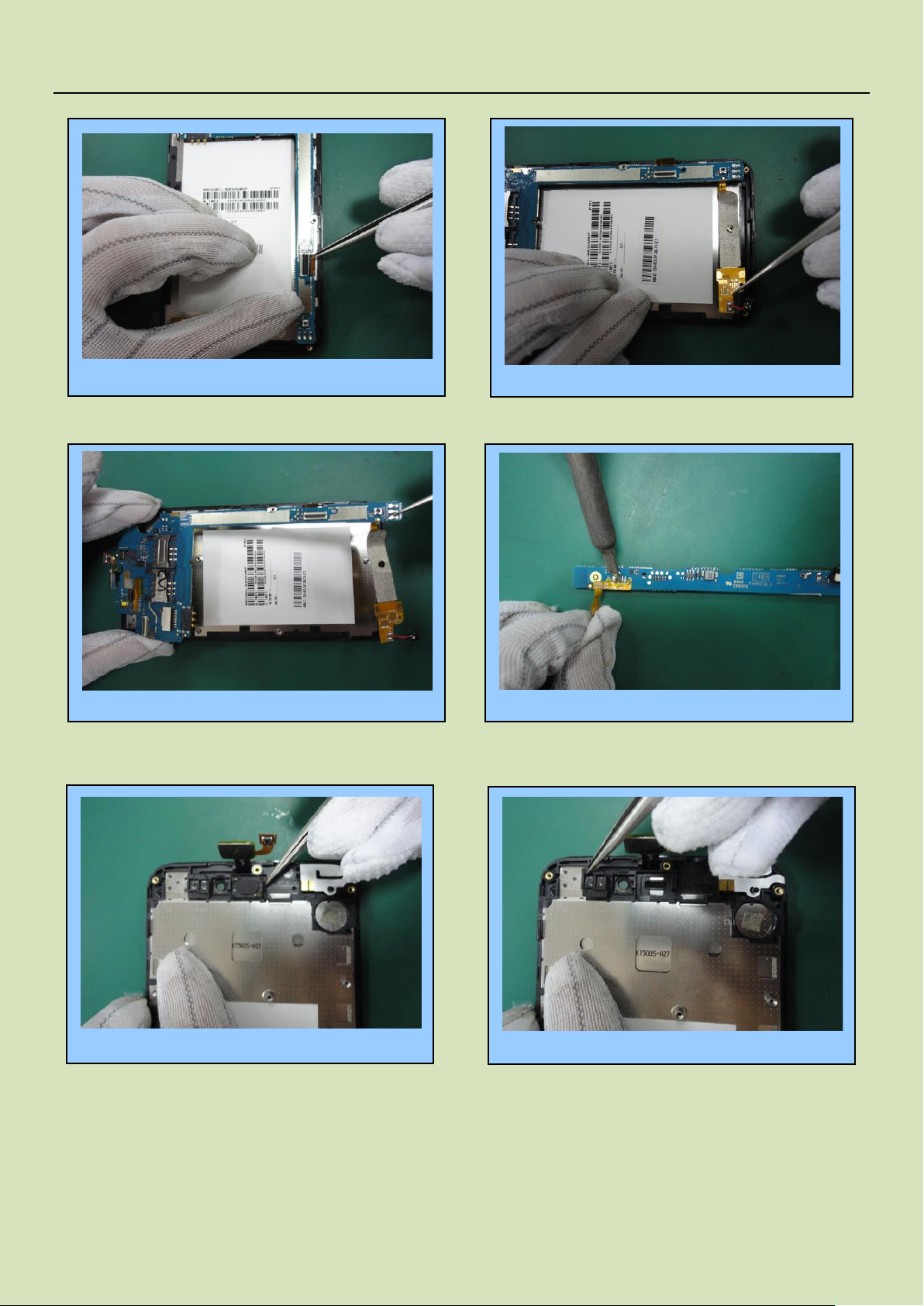
Remove the LCD FPC……………........……7
Remove the speaker FPC………………….........……..8
Take out the PCBA………………….........……..9
Remove the speaker FPC by iron.....……..10
Take out the receiver.....……..11
Take out the light sensation seal rubber…….12
6 / 40
Customer Service Service Manual
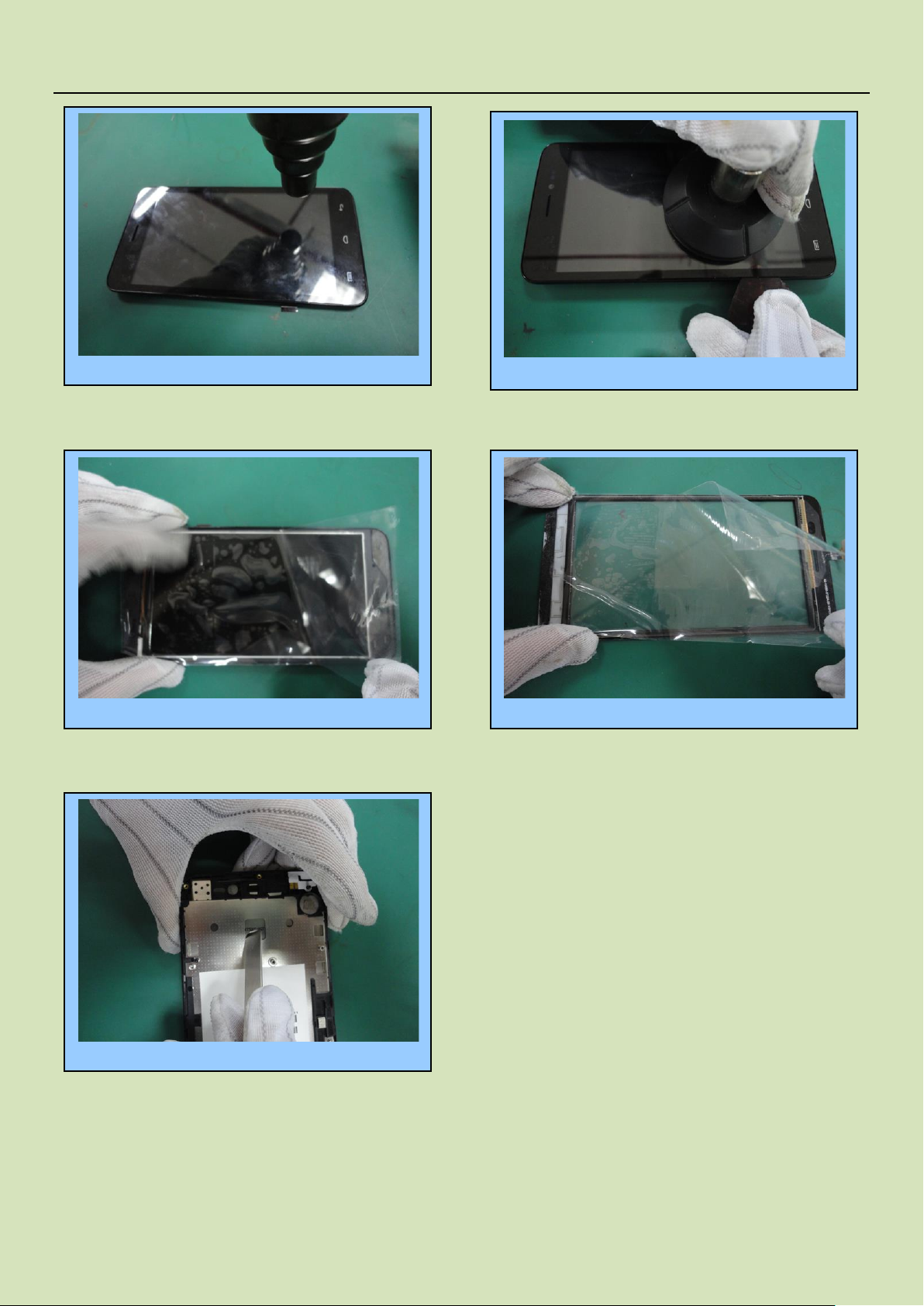
Use heat gun to heat aound the TP 200°C…….13
Remove the TP by port…….14
Stick the protection film onto LCD…….15
Stick the protection film onto TP….….16
Take out the LCD….….17
Finished。。。。。。。
7 / 40
Customer Service Service Manual
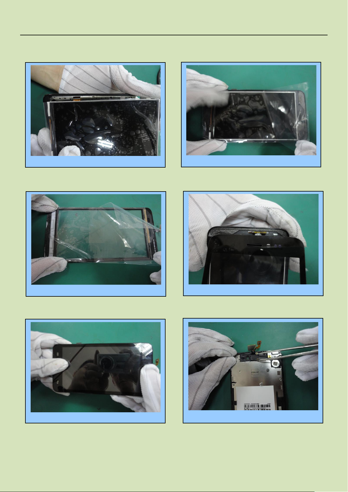
Install the TP……………..……………….………..4
Remove the protection film……..………………....……3
Install the LCD..…..……….…..…1
Remove the protection film……………………………….2
Impact the LCD……….………...5
Install the receiver…………………...... 6
3.2 ASSEMBLY
8 / 40

Customer Service Service Manual
Install the Light sensation seal rubber…...... 7
Solder the speaker FPC…...... 8
Install the PCBA…...... 9
Install the speaker FPC…...... 10
Install the LCD FPC…...... 11
Install theTP FPC…...... 12
9 / 40
Customer Service Service Manual
Install the camera …...... 13
Solder the vibrator by iron …...... 14
Install the back cover…...... 15
Fasten the 11 screws…...... 16
Install the battery cover…...... 17
Finished……
10 / 40
Customer Service Service Manual
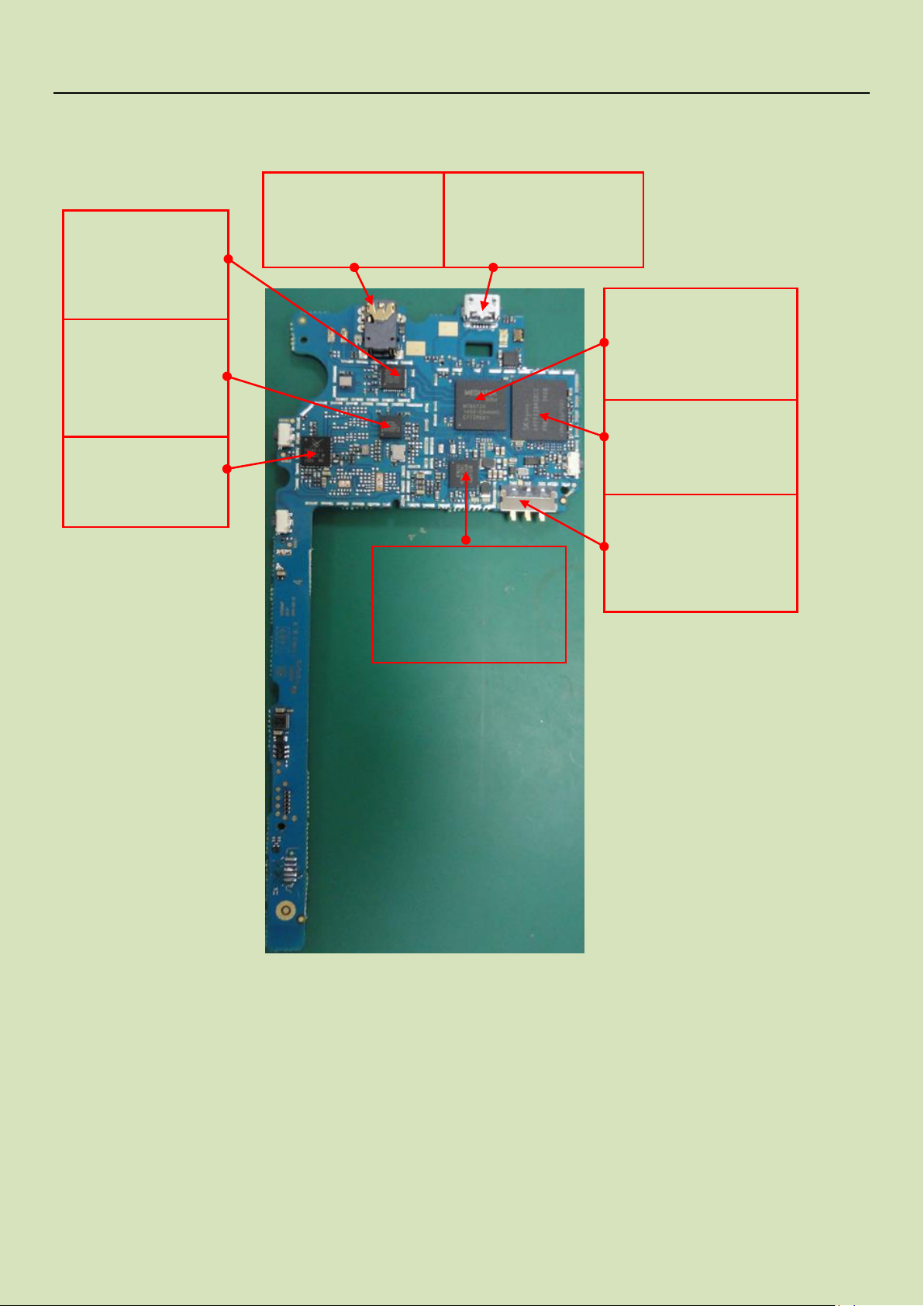
J1003 Earphone connector.
bug by damaged.
Earphone no sound
J1203 I/O Connector
bug by damaged No charge in,
Cannot upgrade Software
U301 Flash Bug by damaged
Cannot power on, cannot
upgrade software.
U101 CPU Bug by damaged
Cannot power on. No RF
signal. No display or display
abnormality
U401 Power IC Buy by
damaged,Cannot power on.
No charge in.
Speaker no sound.
U701 BT/WIFI/FM/GPS
IC. Buy by damaged.
BT/WIFI/FM/GPS Not
work
J1205 Battery connector
Bug by damaged.
Not power on.
Not charge in
U501 RF IC
Bug by damaged.
No signal
Can’t power on.
U605 GSM PA
Bug by damaged.
No signal. Large current
CHAPTER 4.SYSTEM BLOCK DIAGRAM
4.1、PCBA A-Side
11 / 40
Customer Service Service Manual
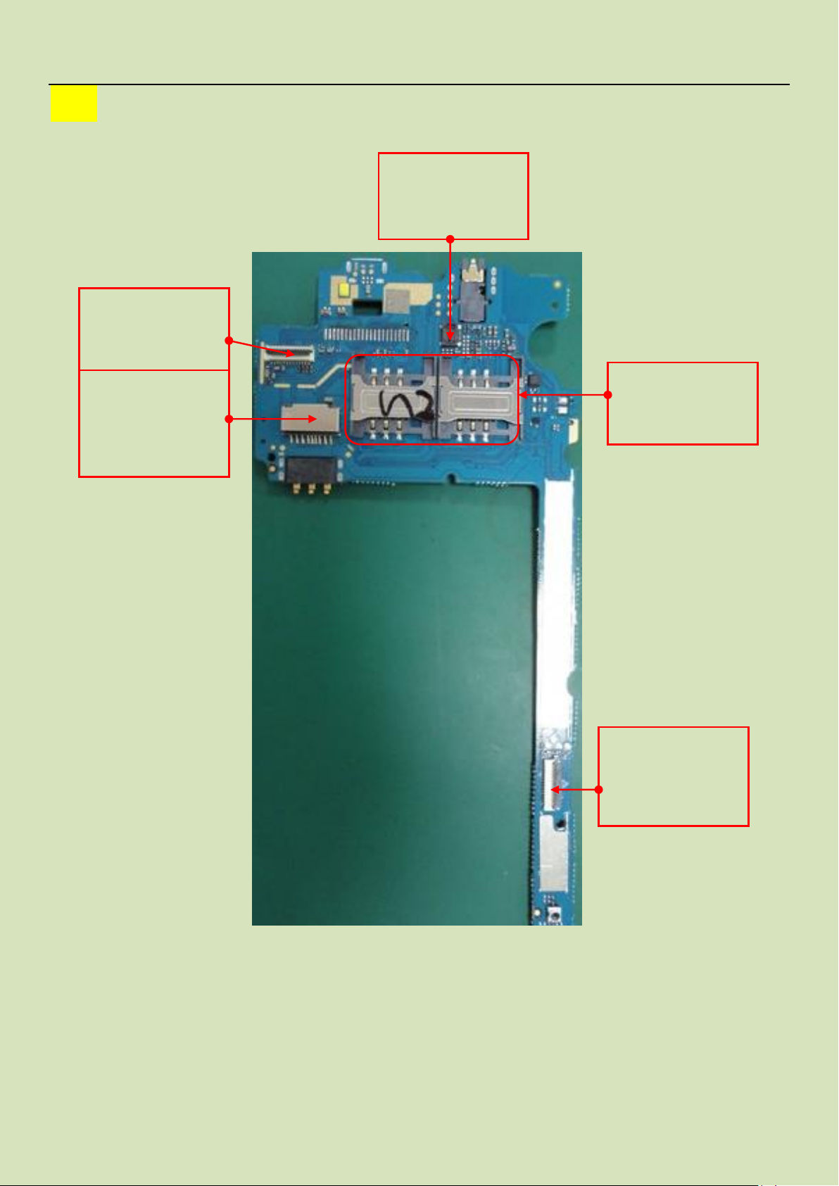
J1204 T-Flash connector
Bug by damaged.
Can't Access T-Flash
Card.
J901 Camera connector
Bug by damaged.
Can’t take photos.
J1201 J1202 SIM
connector
Bug by damaged.
J802 TP Connector
Bug by damaged.
TP not work.
J801 LCD Connector
Bug by damaged.
LCD No display or
display abnormality
PCBA-B-Side
12 / 40
 Loading...