

Expert Sleepers Disting mk4 User Manual

disting mk4
Firmware v4.4
User Manual
Page 1

Copyright © 2017 Expert Sleepers Ltd. All rights reserved.
This manual, as well as the hardware and software described in it, is furnished under licence and
may be used or copied only in accordance with the terms of such licence. The content of this
manual is furnished for informational use only, is subject to change without notice, and should not
be construed as a commitment by Expert Sleepers Ltd. Expert Sleepers Ltd assumes no
responsibility or liability for any errors or inaccuracies that may appear in this document.
Page 2

Table of Contents
Introduction..........................................................................................................................................6
Installation............................................................................................................................................6
Power requirements.........................................................................................................................6
Inputs, Outputs and Controls................................................................................................................6
Inserting a MicroSD card.....................................................................................................................6
Startup...................................................................................................................................................7
The encoder & menu system................................................................................................................7
Selecting an algorithm..........................................................................................................................7
Settings.................................................................................................................................................8
Help......................................................................................................................................................8
Parameters............................................................................................................................................9
Knob Recorder......................................................................................................................................9
Tap Tempo..........................................................................................................................................10
Favourites...........................................................................................................................................10
Presets.................................................................................................................................................10
Preset 0...........................................................................................................................................11
Select Bus...........................................................................................................................................11
SD Card Playback...............................................................................................................................11
Supported MicroSD cards..............................................................................................................11
Supported audio files.....................................................................................................................12
Supported MIDI files.....................................................................................................................12
File naming & Playlists..................................................................................................................12
Audio Playlist Format....................................................................................................................12
MIDI Playlist Format.....................................................................................................................14
Example Files................................................................................................................................15
MIDI/CV conversion.....................................................................................................................15
Scala Support......................................................................................................................................15
Organising the files on the card.....................................................................................................15
Example Files................................................................................................................................15
Scale Playlist Format.....................................................................................................................16
Possible Sources of Error...............................................................................................................16
Algorithm Overview...........................................................................................................................17
A-1 Precision Adder......................................................................................................................18
A-2 Four Quadrant Multiplier........................................................................................................18
A-3 Full-wave Rectifier.................................................................................................................19
A-4 Minimum/maximum...............................................................................................................19
A-5 Linear/Exponential Converter................................................................................................19
A-6 Quantizer................................................................................................................................20
A-7 Comparator.............................................................................................................................21
A-8 Dual Waveshaper....................................................................................................................21
B-1 Sample and Hold.....................................................................................................................22
B-2 Slew Rate Limiter...................................................................................................................22
B-3 Pitch and Envelope Tracker....................................................................................................22
B-4 Clockable Delay/Echo............................................................................................................23
B-5 LFO.........................................................................................................................................24
B-6 Clockable LFO........................................................................................................................25
B-7 VCO with linear FM...............................................................................................................25
B-8 VCO with waveshaping..........................................................................................................26
Page 3

C-1 Precision Adder (fractional offsets)........................................................................................26
C-2 Voltage Controlled Delay Line...............................................................................................27
C-3 Clockable Ping Pong Delay (Z feedback)...............................................................................27
C-4 Clockable Ping Pong Delay (Z input pan)..............................................................................28
C-5 Resonator................................................................................................................................28
C-6 Vocoder...................................................................................................................................29
C-7 Phaser......................................................................................................................................30
C-8 Bit Crusher..............................................................................................................................30
D-2 Tape Delay..............................................................................................................................32
D-3 Waveform Animator...............................................................................................................32
D-4 State Variable Filter................................................................................................................33
D-5 LP/HP Filter............................................................................................................................34
D-6 LP/BP Filter............................................................................................................................34
D-7 BP/HP Filter...........................................................................................................................34
D-8 BP/Notch Filter.......................................................................................................................35
E-1 AR Envelope...........................................................................................................................35
E-2 AR Envelope (with push)........................................................................................................36
E-3 AR Envelope & VCA.............................................................................................................36
E-4 AR Envelope & VCA (with push)..........................................................................................37
E-5 Dual AR Envelope..................................................................................................................38
E-6 Dual AR Envelope (with push)...............................................................................................38
E-7 Euro to Buchla Converter.......................................................................................................39
E-8 Buchla to Euro Converter.......................................................................................................39
F-1 Clockable AD Envelope (with mute)......................................................................................40
F-2 Clockable AD Envelope (with gate).......................................................................................40
F-3 Clockable AD Envelope (with trigger)...................................................................................41
F-4 Clockable AD Envelope & VCA............................................................................................41
F-5 Shift Register Random CVs....................................................................................................42
F-6 Shift Register Random Quantized CVs...................................................................................43
F-7 Shift Register Random Triggers..............................................................................................44
F-8 Shift Register Random Dual Triggers.....................................................................................44
G-1 ES-1 Emulation.......................................................................................................................45
G-2 ES-2 Emulation.......................................................................................................................45
G-3 Pitch Reference.......................................................................................................................46
G-4 Frequency Reference..............................................................................................................46
G-5 Tuner.......................................................................................................................................47
G-6 MIDI Clock.............................................................................................................................47
G-7 MIDI/CV................................................................................................................................49
G-8 CV/MIDI................................................................................................................................49
H-1 Crossfade/Pan.........................................................................................................................50
H-2 Dual Sample and Hold............................................................................................................50
H-3 Dual Quantizer (Z scale).........................................................................................................51
H-4 Dual Quantizer........................................................................................................................52
H-5 Dual Euclidean Patterns..........................................................................................................53
H-6 Dual Delayed Pulse Generator...............................................................................................53
H-7 Noise.......................................................................................................................................54
I-1 Audio Playback........................................................................................................................55
I-2 Clocked Audio Playback..........................................................................................................55
I-3 Audio Playback with V/Oct.....................................................................................................56
I-4 Audio Playback with Z Speed..................................................................................................56
Page 4

J-1 MIDI File Playback (Clocked).................................................................................................57
J-3 MIDI File Playback (Free Running)........................................................................................57
J-4 Audio Playback with End CV..................................................................................................58
J-5 Audio Recorder........................................................................................................................58
K-1 Wavetable VCO......................................................................................................................59
Loading wavetables...................................................................................................................59
K-5 Programmable Quantizer........................................................................................................61
L-1 Stereo Reverb..........................................................................................................................62
L-2 Mono-to-Stereo Reverb...........................................................................................................62
L-3 Dual Reverb............................................................................................................................63
L-5 Stereo Chorus..........................................................................................................................64
L-6 Mono Chorus...........................................................................................................................64
MIDI I/O.............................................................................................................................................66
Introduction....................................................................................................................................66
Connections...................................................................................................................................66
Breakout module............................................................................................................................66
MIDI "Low-Voltage Signaling"....................................................................................................66
Controlling the disting mk4 via MIDI...........................................................................................67
MIDI Thru......................................................................................................................................67
Calibration..........................................................................................................................................68
Calibration Procedure....................................................................................................................68
Calibration Data.............................................................................................................................68
Firmware Updates..............................................................................................................................70
Acknowledgments..............................................................................................................................71
Page 5

Introduction
Congratulations on your purchase of an Expert Sleepers disting mk4. Please read this user manual
before operating your new module.
Installation
House the module in a Eurorack case of your choosing. The power connector is Doepfer standard. If
using the power cable supplied with the module, the red edge of the cable is nearest the bottom of
the PCB, and carries -12V. ("-12V" is marked on the PCB itself next to this end of the connector.)
Be sure to connect the other end of the power cable correctly, again so -12V corresponds to the red
stripe on the cable.
Power requirements
The disting mk4 draws 51mA on the +12V rail, and 19mA on the -12V rail.
It does not use the 5V rail.
Inputs, Outputs and Controls
From top to bottom, the disting has
• A rotary encoder/push button, named 'S'.
• A dot matrix display.
• A MicroSD card slot.
• A knob, referred to as the 'Z' control, which controls some
aspect of the algorithm. This knob also has a push button
function.
• Three input sockets.
◦ The top input is the 'Z' CV input, which controls the
same thing as the 'Z' knob. The two are added
together.
◦ The other two inputs are 'X' and 'Y', and their function
depends on the current algorithm.
• Two output sockets, named 'A' and 'B'.
The sockets are illuminated to reflect the voltage at the socket (or in the case of 'Z', the combined
voltage of the input and the knob). Red indicates a positive voltage; blue indicates a negative
voltage.
Inserting a MicroSD card
The disting's MicroSD card slot is to the left of the display.
The exposed contacts of the card should face towards the display; the angled side of the card itself
points up.
The slot is of the "push-push" type - to remove the card, push it in slightly and it will spring out.
Page 6

Startup
Video
When the module powers up it first runs through some patterns on its display. The sequence is as
follows:
• Each of the seven columns in turn, from left to right.
• Each of the five rows in turn, from bottom to top.
It then shows the bootloader version (e.g. "b1") and the current firmware version (e.g. "v4.0").
If after the above the disting shows the message "Uncalibrated", then the calibration data in flash is
missing or corrupt. A default calibration will be used, but for accurate results, please recalibrate the
module (see below).
The encoder & menu system
Video
Pressing the encoder ('S') enters the disting's menu system, which is indicated by the display
blinking.
At this time the menus are particularly simple, there being only four menu items to choose from,
only one of which you will normally need. In general, the menu system works like this:
• Press the encoder to enter menu mode.
• Turn the encoder to select the menu item, and press to select.
• At this point the behaviour depends on the chosen menu item.
Pressing 'Z' at any time cancels and exits the menus.
The menu items are:
• Algorithm - select algorithm
• Help - access help
• Settings - change settings
• Calibrate - begin calibration
◦ If you accidentally enter this mode, press the Z knob to cancel
Selecting an algorithm
Video
There is a single list of algorithms, named A1 up to P8 (i.e. A1, A2, ... up to A8, then B1, B2 etc.).
See below for details.
The algorithm can be chosen via menu 1 "Algorithm". Press the encoder twice (to enter the menu,
and to select "Algorithm"). Then turn the encoder to select the algorithm. Finally, press the encoder
again to switch to the chosen algorithm.
Alternatively, you can switch between algorithms by pushing and holding the S knob while turning
it, though this does visit every algorithm you pass through, rather than jumping directly to the
Page 7

chosen one, as is the case when using the menu.
Settings
Video
The disting has a number of settings, which are stored in flash memory. They are accessed by menu
4 "Settings". Once you've entered the Settings menu, turn the encoder to select the setting to
change.
The settings are:
• Brightness – set the display brightness
• Recall enable – enable/disable recall from the Select Bus (see below)
• In MIDI ch – the input MIDI channel
• Out MIDI ch – the output MIDI channel
• Thru MIDI – enables a soft MIDI thru
• Pgm Chng Alg – controls whether MIDI program change messages select the current
algorithm (1) or load a preset (0)
Once you've chosen the setting to change, press the encoder to select it, at which point the setting's
current value will be shown. Turn the encoder to change the value. Then press the encoder to accept
and store the value into flash, or press Z to leave the menu without storing the value.
Help
Video
Accessing 'Help' from the menu displays algorithm-specific information. The help is loaded from
the MicroSD card, if present (else the message "No card" is displayed), and scrolled across the
display. To exit the help function, press Z.
The help text is a simple plain text file on the card, so it can be freely edited (e.g. to put your own
choice of information first, or to translate it into a different language).
Page 8
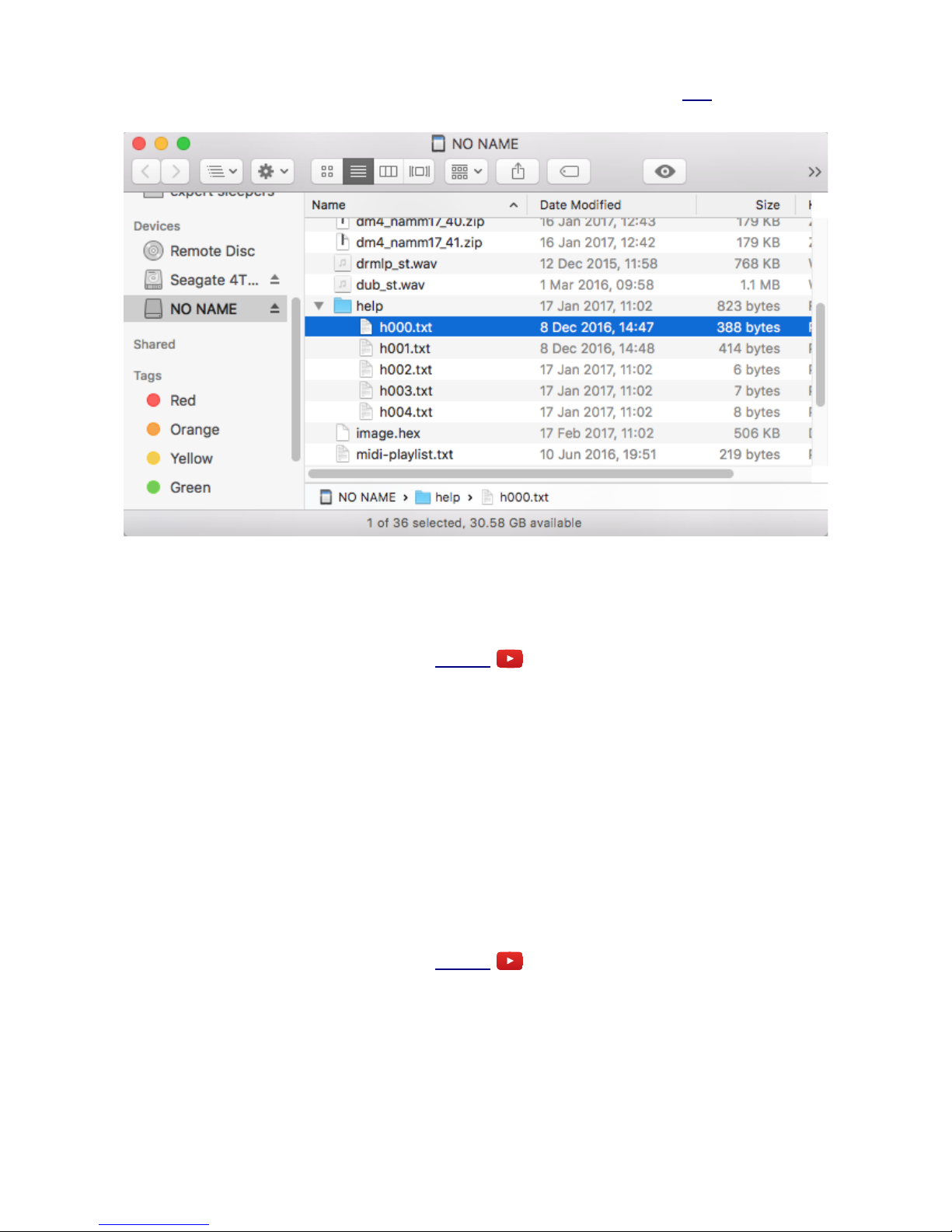
The default set of help files can be downloaded from the firmware update page here. Simply unzip
the file onto your MicroSD card. The file structure should look something like this:
i.e. the 'help' folder is at the root level of the card, and inside is a file per algorithm, named
'hXXX.txt', where XXX is the algorithm number, starting from zero for algorithm A1.
Parameters
Video
In addition to the control provided on the Z knob, each algorithm may have up to six 'parameters',
offering further control over the algorithm's operation.
Unlike the Z control, which is sampled at the same high rate as the X & Y inputs, parameters should
be considered coarse, non-real-time adjustments to the algorithm. They may cause glitching in the
outputs when changed.
Parameters are adjusted via the S knob. When changed, the parameter value is displayed for a
couple of seconds.
If an algorithm has more than one parameter, pressing the Z knob cycles through them. The current
parameter number is displayed briefly followed by its name.
Knob Recorder
Video
In many algorithms which do not use a Z knob press for another purpose, pressing Z offers a 'knob
recorder' function.
When this is available, holding Z down while turning it causes the Z value changes to be recorded.
As soon as the knob is released, the recording is played back in a loop. To end playback, turn the Z
knob slightly to regain manual control.
Page 9

The maximum duration of knob recording is a little under 14 seconds.
Tap Tempo
Video
Some algorithms (notably the Clockable LFO and Clockable Delay/Echo) use a press of the Z knob
as a 'tap tempo' function. In these modes, pressing Z has the same effect as sending a clock pulse
into the clock input. For example, pressing Z twice will set the delay time/LFO period to the time
between the two button presses.
Note that if the algorithm is dividing down the clocked frequency, pressing Z twice will not set the
output to the division of the time between the two presses; rather, it will be the time between a
corresponding number of button presses. E.g. if the Clockable LFO is set to 1/4 (divide by 4), the
LFO time will be set by pressing the Z button 5 times, and it will only change on the 5th press.
Favourites
You can define your own list of 16 'favourite' algorithms, via a text file on the MicroSD card.
The favourites are accessed as algorithms O1-P8. If no favourites are defined, or if there are empty
slots, the disting runs algorithm A1, the Precision Adder.
The favourites are read from the SD card, if present, at power on. They are then stored in the
disting's flash memory, and so persist even after the card is removed.
The favourites file is a simple text file which must be named 'favourites.txt' and placed in the root of
the SD card (not inside any folder). The contents look something like this:
disting favourites v2
B8 VCO
a1
C5 resonator
I4 SD z speed
b5 LFO
e6 dual AR w/ push
The first line must be "disting favourites v2". Subsequent lines specify an algorithm to add to the
list of favourites. After 16 algorithms, any further lines are ignored.
Each algorithm is specified as its two character name (a letter followed by a number). Any further
text after the algorithm number is ignored, so you can add a descriptive string (as in the example
above) to help you remember what's what.
Presets
Video
The disting can store its current state to flash memory as a preset. The contents of a preset are
• the chosen algorithm, and
• the parameter values.
Anything controlled by the Z knob/CV is not stored – its value is always defined by the knob
position and CV input.
Page 10

There are 64 preset slots. Presets are saved and recalled using the menu. To save a preset:
1. Press the encoder to enter menu mode.
2. Turn the encoder once (to show 'Save'), and press to confirm.
3. Turn the encoder to choose the preset slot.
4. Press the encoder to complete the save.
As usual, pressing Z at any point exits the menu without saving.
To load a preset:
1. Press the encoder to enter menu mode.
2. Turn the encoder twice (to show 'Load'), and press to confirm.
3. Turn the encoder to choose the preset slot.
4. Press the encoder to complete the load.
Preset 0
Preset 0, the first slot, is special:
• The contents of preset 0 are loaded at power-up.
• When switching algorithm, the new algorithm state is saved to preset 0.
1
Therefore if you want to save the disting's state so it powers up as it is currently, you can manually
save to preset 0, which is “click, turn, click, click” on the encoder.
Select Bus
Video
If enabled in the settings, the disting mk4 will respond to save/recall messages on the Select Bus.
The Select Bus is a means of inter-module communication currently supported by a handful of
modules from various manufacturers, including the Malekko Varigate 8+, Macro Machines Storage
Strip and the Make Noise Tempi.
Note that the disting only responds to save/recall messages. It does not initiate them.
SD Card Playback
Supported MicroSD cards
In theory any MicroSD card will work, but in practice there is a huge variety of cards on the market
and we cannot possible test them all. We recommend 32GB SDHC cards, and in particular have
found "SanDisk Extreme 32GB microSDHC UHS-I U3" cards work well.
The MicroSD card must be formatted in FAT32 format, which is the as-sold state for many cards. If
not, cards can easily be reformatted to FAT32 in Windows or macOS.
1 The thinking here is that if you forget to save your preset before turning off the power, at least the disting will come
back up in the same algorithm next time you start.
Page 11

Supported audio files
As of now, the only supported audio file format is 16 bit WAV, mono or stereo. Any sample rate
can be used, however.
Since higher sample rates impose greater bandwidth demands on the SD card streaming, we suggest
you use the lowest sample rate that gives acceptable audio quality. All our testing generally uses
44.1kHz files.
Note that because the disting's outputs are DC-coupled, the 'audio' files can actually contain
recorded or generated CVs, so all the sample playback modes can also be used as complex
modulation or sequencing sources.
Supported MIDI files
Currently we support Format 0 files (single track). The division field of the header chunk must be in
"ticks per quarter note" format.
Happily this is the format that Ableton Live spits out if you do "Export MIDI Clip".
File naming & Playlists
All files need to be in the root of the drive i.e. not inside any folder.
For audio files, we still support the legacy naming convention from the early disting mk3
implementation, which required that files be named 'sampleXX.wav' where XX is a decimal number
from 00 to 31 e.g. sample01.wav, sample23.wav. However the playlist file is the preferred method
going forward.
The playlist file specifies what audio/MIDI files the algorithm will use, how they will be ordered,
and what playback setings they will use. It is a simple text file, as described below.
By default, audio algorithms look for a playlist file called 'playlist.txt' and MIDI algorithms look for
'midi-playlist.txt'. However, each algorithm first looks for an algorithm-specific playlist file, the
name of which is specified in the algorithm descriptions below.
The playlist files must be plain text. Note that TextEdit on macOS defaults to rich text. From the
'Format' menu choose, 'Make Plain Text'.
Audio Playlist Format
An audio playlist file might look something like this:
disting playlist v1
-loop=0
-gap=0
-fadeIn=0
-fadeOut=0
TR66_BD_aOrig_b_R1.wav
-fixedPitch=0.9
TR66_Snare_aOrig_b_R1.wav
sample01.wav
-loop=1
-ramp=1
funky_lp.wav
-loop=1
-triggers=4
586447main_JFKwechoosemoonspeech.wav
Page 12
-loop=1
This breaks down as:
• The header: "disting playlist v1"
• Default settings (optional)
• List of audio files
• Per-file settings after each file (optional)
Files may appear more than once in the playlist, with the same or different settings.
Settings are in the format "-" <setting name> "=" <setting value>
Settings that appear before any audio file apply globally to all the files in the playlist, unless
overridden by the per-file settings.
The available settings are as follows.
Setting Default Description
loop 1 Whether the sample loops (value 1) or is a one-shot (value 0).
fadeOut 3
Fade out to apply when a sample is retriggered, in
milliseconds.
fadeIn 3
Fade in to apply when a sample is retriggered, in
milliseconds.
gap 3 Gap (silence) between fade out and fade in, in milliseconds.
retriggerOnSampleChange 1 See below.
fixedPitch 0
Play the sample at a fixed pitch, not controlled by the pitch
CV (if any).
ramp 0 Switch Output B to emit a ramp CV.
triggers 0 Switch Output B to emit trigger pulses.
clocks 4
Set the number of clocks per loop for the Clocked Audio
Playback algorithm.
wavelength 600
Set the number of sample frames per waveform for the
Wavetable VCO algorithm.
The fades are useful when retriggering samples, especially when starting them at arbitrary points
within the sample, to avoid clicks. However, for maximum responsiveness when triggering, say,
drum samples, set the fades and gap to zero.
The default behaviour (with retriggerOnSampleChange=1) when selecting a new sample
(via S or Z depending on algorithm) is to immediately begin playing the new sample. If a sample
has retriggerOnSampleChange=0 (or, if the default is set to 0) then the next sample does not
begin playback until triggered by the input. A typical use case for this would be when you have a
set of one-shot (say, drum) samples and you want to trigger each sample and have it play until the
next trigger, not changing in the middle if the sample select CV changes. At an extreme, you could
in this case feed white noise into the sample select CV, to choose a random sample on each trigger.
The fixedPitch setting is a floating point number, where 1.0 corresponds to playing the sample
at its natural speed, 0.5 means play it at half speed etc. fixedPitch=0 (the default) means that
the sample respects the CV-controlled pitch.
ramp=1 outputs a rising ramp from 0V to +8V corresponding to the current position in the sample.
ramp=-1 outputs a falling ramp (+8V to 0V).
Page 13

triggers outputs a number of triggers during the sample e.g. triggers=4 will output 4 trigger
pulses, equally spaced over the sample length. The triggers are +5V pulses lasting about 10ms. The
maximum number of triggers per sample is 32767.
Video
ramp and triggers are mutually exclusive. The last setting in the playlist file for a given sample
is the one that takes effect.
The maximum number of sample files per playlist is 64. Files beyond that limit are ignored.
MIDI Playlist Format
A MIDI playlist file might look something like this:
disting playlist v1
-zeroVNote=60
bach_2ptinv.mid
CDE_bend.mid
-bendRange=12
CDE_bend.mid
-loop=0
cc1_2.mid
-cc1offset=-1.5
-cc1scale=3
-cc2offset=2
-cc2scale=6
This breaks down as:
• The header: "disting playlist v1"
• Default settings (optional)
• List of MIDI files
• Per-file settings after each file (optional)
Files may appear more than once in the playlist, with the same or different settings.
Settings are in the format "-" <setting name> "=" <setting value>
Settings that appear before any MIDI file apply globally to all the files in the playlist, unless
overridden by the per-file settings.
The available settings are as follows.
Setting Default Description
loop 1 Whether the MIDI file loops (value 1) or is a one-shot (value 0).
zeroVNote 48 MIDI note number corresponding to zero Volts output pitch CV.
bendRange 2 Pitch bend range, in semitones.
cc1offset 0 Offset for CC#1, in Volts.
cc1scale 5 Range for CC#1, in Volts.
cc2offset 0 Offset for CC#2, in Volts.
cc2scale 5 Range for CC#2, in Volts.
The maximum number of MIDI files per playlist is 32. Files beyond that limit are ignored.
Page 14

Example Files
A simple example playlist and some audio files which are known to be formatted correctly can be
downloaded here2.
MIDI/CV conversion
The are two primary modes of MIDI/CV conversion, which can be mixed within a MIDI file:
1. Note on/off messages, and pitch bend messages, are used to generate a pitch CV from output
A and a gate CV from output B.
2. CCs #1 & #2 are used to directly control voltages on outputs A & B respectively. The 7 bit
CC value (0-127) is converted to a voltage according to the scale and offset settings (by
default, 0-5V).
Scala Support
Some disting algorithms support microtonal scales, using files generated by the program Scala3. The
files are loaded from the MicroSD card. See 'Supported MicroSD cards' above.
Organising the files on the card
To use Scala with the disting, you will need a MicroSD card set up as follows.
• An 'scl' folder. A folder named 'scl' in the root folder of the card, which contains all the
scale (.scl) files that you wish to use. Note: you are advised not to simply unzip the archive
of over 4000 scales available from the Scala website onto the card – you will find the disting
slow to load scales if you do.
• A 'kbm' folder. A folder named 'kbm' in the root folder of the card, which contains all the
keyboard mapping (.kbm) files that you wish to use.
• The log tables. The disting uses precomputed mathematical tables when processing the
Scala files. Download the file 'logTables_16_20.bin' from here4 and place it in the root of
your SD card.
• The playlist. A file named 'playlist-scales.txt' which tells the disting which scales to use.
Example Files
A zip file containing some example files, which are known to work, is here5.
2 http://expert-sleepers.co.uk/downloads/content/disting_sd_content.zip
3 http://www.huygens-fokker.org/scala/
4 http://expert-sleepers.co.uk/downloads/content/logTables_16_20.bin
5 http://expert-sleepers.co.uk/downloads/content/disting_example_scales.zip
Page 15

Scale Playlist Format
A scale playlist file might look something like this:
disting playlist v1
-kbm=example.kbm
equal.scl
pyth_7a.scl
pyth_12.scl
johnson_7.scl
-kbm=7.kbm
equal.scl
-kbm=root+fifth.kbm
This breaks down as:
• The header: "disting playlist v1"
• Default settings (optional)
• List of scale files
• Per-file settings after each file (optional)
Files may appear more than once in the playlist, with the same or different settings.
Settings are in the format "-" <setting name> "=" <setting value>
Settings that appear before any scale file apply globally to all the files in the playlist, unless
overridden by the per-file settings.
Currently there is only one setting, which is the name of the keyboard mapping file to use with the
scale file.
Possible Sources of Error
If there is a problem reading or interpreting the scale files, the disting will not be able to use them.
Possible things to check include:
• The scale and keyboard mapping files must obviously be valid Scala format files, that the
Scala application itself will load successfully.
• The scale and keyboard mapping must match – for example, the keyboard mapping must not
refer to scale degrees that the scale does not have.
• For the keyboard mapping files, the reference frequency must be given for a note that is
actually mapped.
Page 16
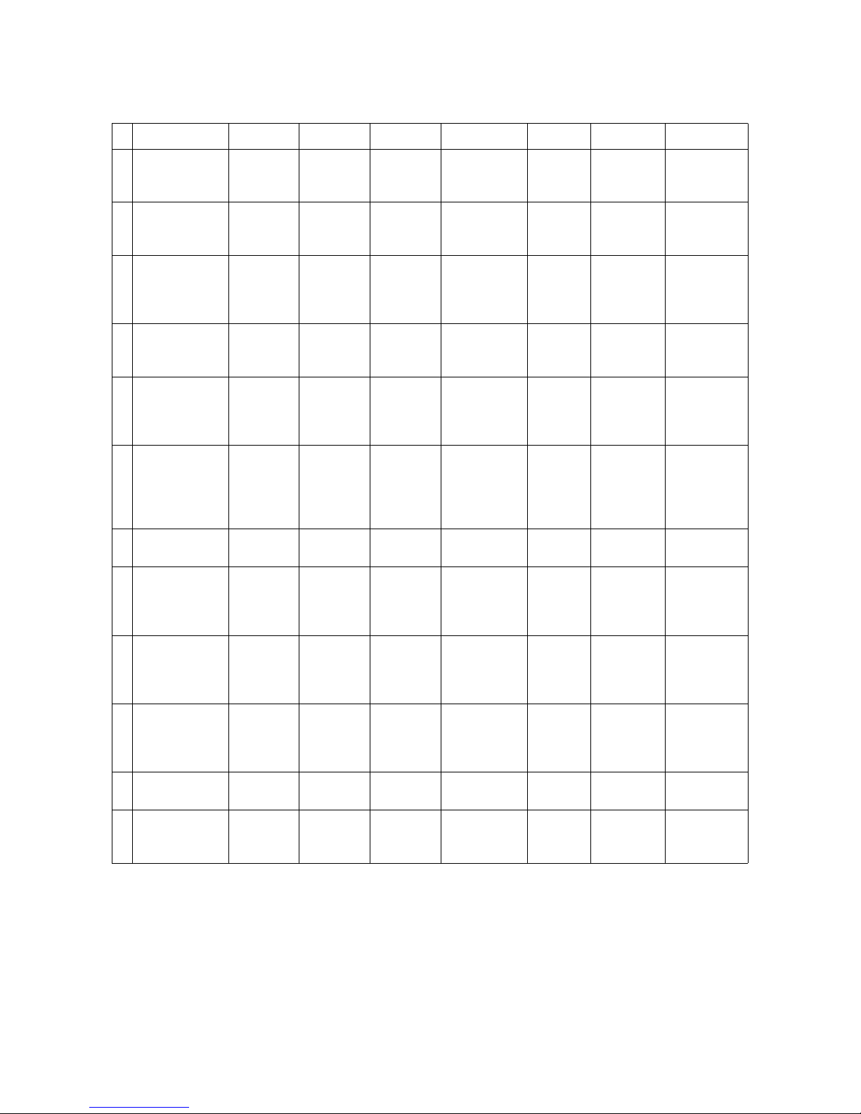
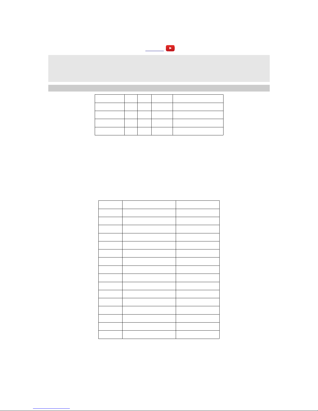
Algorithm Overview
1 2 3 4 5 6 7 8
A
Precision Adder Four
Quadrant
Multiplier
Full-wave
Rectifier
Minimum/
maximum
Linear/
Exponential
Converter
Quantizer Comparator Dual
Waveshaper
B
Sample and
Hold
Slew Rate
Limiter
Pitch and
Envelope
Tracker
Clockable
Delay/Echo
LFO Clockable
LFO
VCO with
linear FM
VCO with
waveshaping
C
Precision Adder
(fractional
offsets)
Voltage
Controlled
Delay Line
Clockable
Ping Pong
(Z
feedback)
Clockable
Ping Pong
(Z input
pan)
Resonator Vocoder Phaser Bit Crusher
D
Tape Delay Waveform
Animator
State
Variable
Filter
LP/HP Filter LP/BP
Filter
BP/HP
Filter
BP/Notch
Filter
E
AR Envelope AR
Envelope
(with push)
AR
Envelope &
VCA
AR
Envelope &
VCA
(with push)
Dual AR
Envelope
Dual AR
Envelope
(with
push)
Euro to
Buchla
Converter
Buchla to
Euro
Converter
F
Clockable AD
Envelope
(with mute)
Clockable
AD
Envelope
(with gate)
Clockable
AD
Envelope
(with
trigger)
Clockable
AD
Envelope &
VCA
Shift Register
Random CVs
Shift
Register
Random
Quantized
CVs
Shift
Register
Random
Triggers
Shift Register
Random Dual
Triggers
G
ES-1 Emulation ES-2
Emulation
Pitch
Reference
Frequency
Reference
Tuner MIDI
Clock
MIDI/CV CV/MIDI
H
Crossfade/Pan Dual
Sample and
Hold
Dual
Quantizer
(Z scale)
Dual
Quantizer
Dual
Euclidean
Patterns
Dual
Delayed
Pulse
Generator
Noise
I
Audio Playback Clocked
Audio
Playback
Audio
Playback
with V/Oct
Audio
Playback
with Z
Speed
J
MIDI File
Playback
(Clocked)
MIDI File
Playback
(Free
Running)
Audio
Playback
with End
CV
Audio
Recorder
K
Wavetable VCO Programmable
Quantizer
L
Stereo Reverb Mono-to-
Stereo
Reverb
Dual
Reverb
Stereo Chorus Mono
Chorus
Page 17
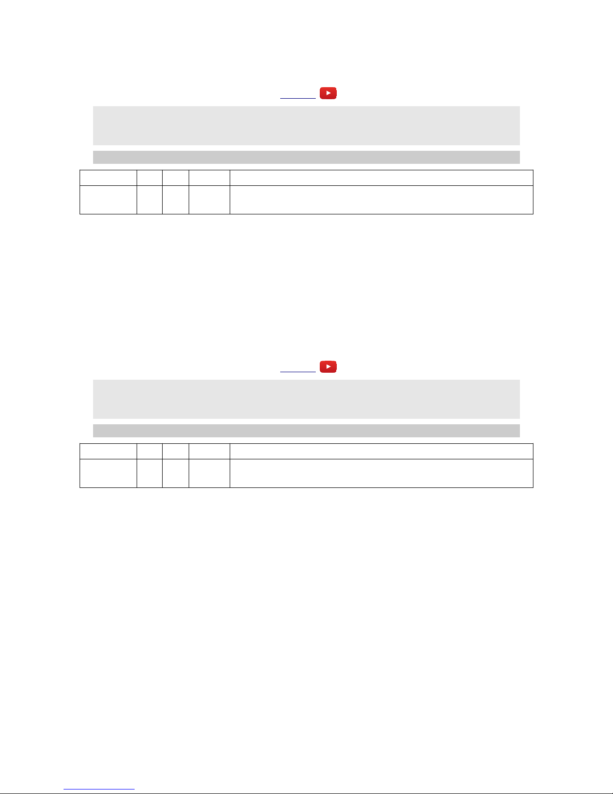
A-1 Precision Adder
Video
A = X + Y + offset
B = X - Y - offset
offset = ±10V in 1V steps derived from Z
Knob recorder enabled
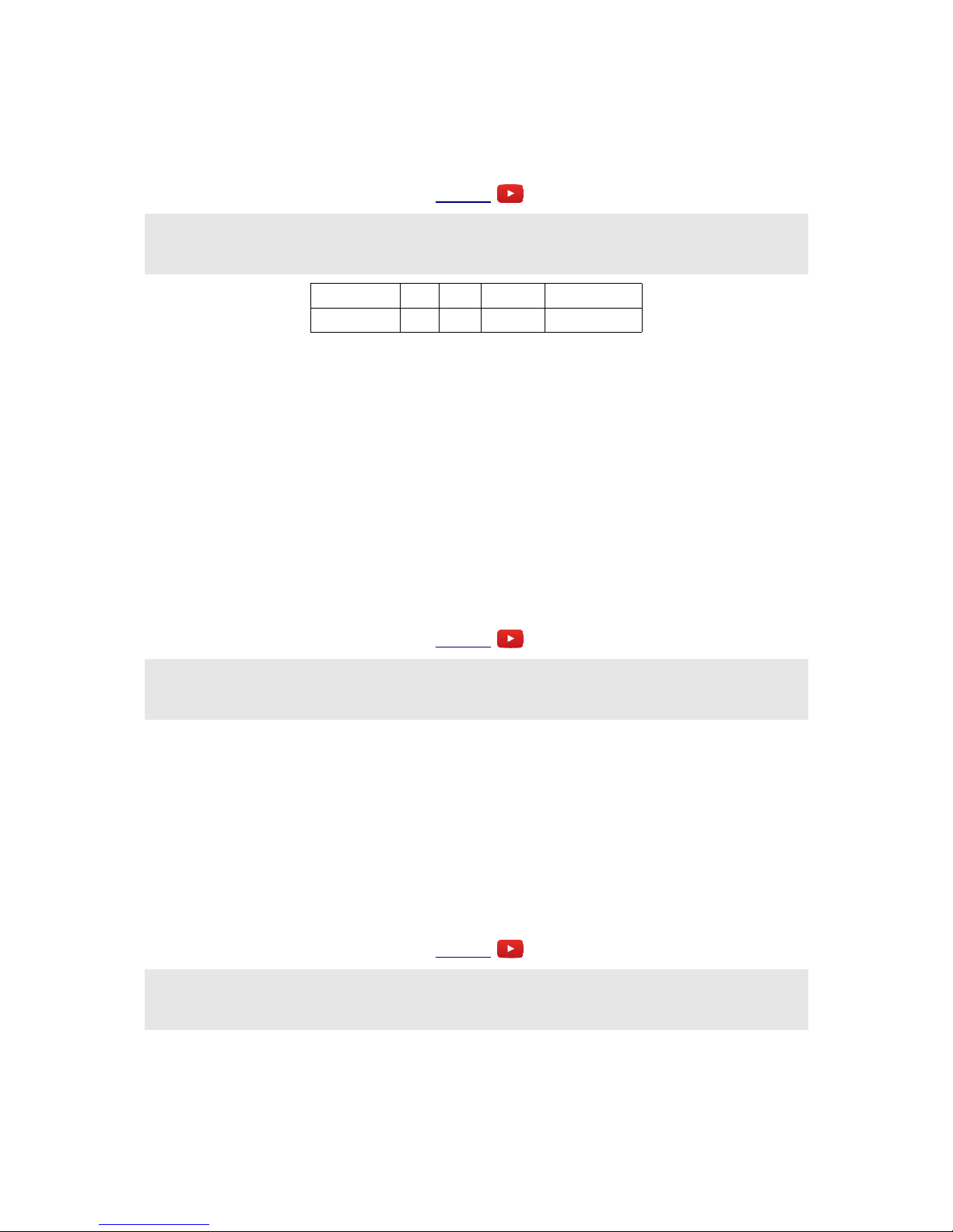
Parameter Min Max Default Description
0 0 1 0
When 1, the offset is not restricted to 1V steps, and changes
smoothly with Z.
Output A is the sum of inputs X & Y; output B is the difference between inputs X & Y. With
nothing plugged into input X, B is therefore simply an inverted copy of Y.
The Z knob/CV sets an offset which is applied to both A and B. The offset is a whole number of
Volts. If X/Y are 1V/Octave pitch CVs, Z is therefore an octave shift control. The maximum shift is
10V, positive or negative.
When Z changes, the offset is shown on the display. After a short while the display reverts to
showing the current algorithm.
A-2 Four Quadrant Multiplier
Video
A = X * Y * scale
B = -X * Y * scale
scale = 1/10 to 10x in steps derived from Z
Knob recorder enabled
Parameter Min Max Default Description
0 0 1 0
When 1, the scale is not restricted to integer steps, and changes
smoothly with Z.
Output A is the result of multiplying inputs X & Y. Output B is the inverse of output A.
If for example X is a signal and Y is an envelope, then this algorithm is a VCA. If both inputs are
signals, then this is a ring modulator.
The Z knob/CV sets a scale factor which is applied to both outputs. The scale is an integer (whole
number) which either multiplies or divides the result, and ranges in value from 1-10.
When Z changes, the scale is shown on the display. If the value shown is negative, it is a divisor
rather than a multipler. Note that there is no value of "-1" since dividing by 1 and multiplying by 1
are the same. After a short while the display reverts to showing the current algorithm.
Page 18
A-3 Full-wave Rectifier
Video
A = abs( X + Y ) or abs( X )
B = abs( X - Y ) or abs( Y )
Z selects mode
This algorithm provides a full-wave rectifier or absolute value function. The Z knob/CV select
between one of two modes. In 'independent' mode, A and B are the absolute values of X and Y,
respectively. In 'combined' mode, A is the absolute value of the sum of X & Y; B is the absolute
value of the difference of X & Y.
When Z changes, the mode is displayed. 'Independent' mode is shown as "-0"; 'combined' mode as
"0". After a short while the display reverts to showing the current algorithm.
A-4 Minimum/maximum
Video
A = min( X, Y )
B = max( X, Y )
Z is gate
Output A is the minimum of inputs X & Y; output B is the maximum of the two inputs. If one input
is zero (or disconnected), this is a half-wave rectifier.
The Z knob/CV provides a gate function. When Z goes higher than approximately 2.5V, the gate
goes high and the outputs follow the inputs according to the min/max relationship. When Z goes
below approximately -1.5V, the gate goes low and the outputs are frozen.
When the gate changes state, "LO" or "HI" is displayed to indicate the gate status. After a short
while the display reverts to showing the current algorithm.
A-5 Linear/Exponential Converter
Video
A = ( 2 ^ X ) * scale
B = log2( Y / scale )
Z is Hz/V scale, centred on 1kHz
This algorithm provides a linear-to-exponential converter and an exponential-to-linear converter.
You might use this to interface 1V/octave modules (Eurorack standard) with Hz/V synths (e.g. old
Korg or Yamaha synths), but it could also be useful within Eurorack e.g. to convert an LFO
(commonly with Hz/V pitch control) to a V/octave oscillator, or to convert an exponential FM input
on a VCO into a linear FM input.
Input X is the exponential input; its corresponding linear output is A. Y is the linear input, whose
exponential output is B.
Z sets the scale factor which is common to both conversions. It sets the number of Hz per Volt, with
arrange from near zero to about 2kHz. The Yamaha CS-15, for example, uses about 1100Hz/V,
which is about half way on the Z knob here.
The zero Volt point on the exponential scale used is C3 (approximately 130.81Hz).
Page 19
A-6 Quantizer
Video
A = quantized( X )
B = trigger on note change
Z chooses scale & function of Y
Y = transpose (Z positive) or trigger (Z negative)
Outputs & Receives MIDI
Parameter Min Max Default Description
0 -1 31 31 Input X attenuation.
1 0 1 0 Transpose mode.
2 -31 31 0 Key.
3 0 31 0 Offset.
Output A is a quantized version of input X; the closest whole-semitone value to the unquantized
V/octave pitch CV X. Output B is a trigger signal which fires whenever output A changes - a 5V
pulse approximately 10ms long.
As well as providing a chromatic scale, this algorithm can also constrain the quantized values to a
musical scale or chord. This is controlled by the Z knob/CV.
When Z changes, the scale is displayed on the LEDs. The scale's number in the following table is
show, and after a short pause, the scale's name. After the name has scrolled across, the display
reverts to showing the current algorithm.
Number Scale Displayed name
0 chromatic Chromatic
1 major scale Major
2 minor scale Minor
3 major triad Triad
4 minor triad 3b+5
5 root+5th Fifth
6 major triad+6th Triad+6
7 minor triad+6th 3b+5+6
8 major triad+7th Triad+7
9 minor triad+7th 3b+5+7
10 root+5th+6th 5+6
11 root+5th+7th 5+7
12 pentatonic major Pent
13 pentatonic minor Minor Pent
14 natural minor scale Nat Minor
15 harmonic minor scale Harm Minor
A further option is controlled by Z being positive or negative. When Z is negative, the scale number
is shown as a negative value.
When Z is positive input Y is a transpose control. The CV on input Y is quantized (to a chromatic
Page 20

scale) and added to the quantized result in one of two ways, controlled by parameter 1. If parameter
1 is zero, the transposition is applied to output A, after input X has been quantized to the chosen
scale. If parameter 1 is one, the transposition is applied to input X before it is forced into the chosen
scale. So, in mode zero the overall key of the quantization is transposed, whereas in mode one the
transposition moves the notes around within the same key.
When Z is negative input Y is a trigger. In this mode, input X is only sampled and converted to a
new quantized value when input Y rises over approximately 1V. (In non-triggered mode, X is
constantly sampled and a new note is output as soon as X moves into the next semitone range.)
Parameter 2 sets the root key of the chosen scale. At zero, the first note of the scale (e.g. C in the
key of C) corresponds to 0V. If the parameter is set for example to 2, the first note of the scale is at
2/12 = 0.1667V - or to look at it another way, if your VCO is tuned so that 0V gives you a C, the
quantizer is now working in the key of D (D major, minor, triad etc. depending on the scale setting).
Parameter 3 sets an offset between the timing of the X & Y inputs (in sample frames). When using
Y as a trigger, it is often a good idea to delay it slightly relative to the pitch, to ensure that the pitch
has changed and settled before the trigger samples a new note.
MIDI Output: each new note (i.e. when the Output B trigger fires) is output as a MIDI note
message on the MIDI channel selected in the settings.
MIDI Input: MIDI note messages received on MIDI channel 1 set parameter 2 (root key).
A-7 Comparator
Video
A = gate from X > Y
B = inverted gate
Z is hysteresis
Output A is a gate signal (zero or +5V), high when input X has a higher voltage than input Y.
Output B is an inverted copy of A (i.e. +5V when A is 0V and vice versa.)
The Z knob/CV input sets the hysteresis (for an explanation of hysteresis see here). Inputs of
approximately 0-4V correspond to hysteresis values of approximately 0-10V. Negative values are
clamped at zero.
A-8 Dual Waveshaper
Video
A = folded X
B = triangle-to-sine Y
Z is gain
Knob recorder enabled
This algorithm provides two independent waveshaping functions. The Z knob/CV is a gain control,
with a range of approximately 30x. Negative values of Z invert the signal.
Input X/output A provide what is usually termed a wavefolder. This increases the harmonic content
of the sound in interesting ways, especially as the gain changes.
Input Y/output B provide a triangle-to-sine waveshaper. Used on most audio this is a relatively
gentle form of overdrive/saturation. However, when fed with the right level of triangle wave, the
Page 21
output is exactly a sine wave, which is useful when you have a triangle wave VCO handy but really
want a pure sine wave instead.
B-1 Sample and Hold
Video
A = X when Y exceeds 1V
B = noise ±8V
Z is slew rate
Parameter Min Max Default Description
0 0 1 0 Mode.
If parameter 0 is 0 (the default):
Output A is a sample of input X, taken when the trigger input Y goes over 1V. (Sample and Hold)
If parameter 0 is 1:
Output A follows input X while input Y is over 1V. When Y falls below 0.5V, output A is held
until Y goes over 1V again. (Track and Hold)
Output B is a white noise signal, with range ±8V. A noise signal is commonly fed into the input of a
sample and hold device to generate clocked random voltages.
The Z knob/CV controls the slew rate of output A. At the minimum value of Z, changes in A are
instantaneous. As Z increases, changes in A take place more slowly.
Pressing the Z knob triggers a sample manually.
B-2 Slew Rate Limiter
Video
A = linear slew rate limited ( X + Y )
B = log slew rate limited ( X + Y )
Z is slew rate
Outputs A & B are both slew rate limited copies of the sum of X & Y. Output A uses linear slew
rate limiting; a step change in the input will typically result in a ramp output, until the output
reaches its desired value, at which point it will be constant. Output B uses logarithmic slew rate
limiting; a step change in input results in a smooth curve that gradually approaches the desired
value.
The Z knob/CV controls the slew rate for both outputs. At the minimum value of Z, changes are
very rapid. As Z increases, changes take place more slowly.
B-3 Pitch and Envelope Tracker
Video
A = V/octave pitch derived from X, plus Y
B = envelope dervied from X
Z is slew rate for envelope
This algorithm provides pitch and envelope tracking of an incoming audio signal. It will track
frequencies down to about 27Hz, which is just below the lowest note on a standard 88 key piano.
Page 22
 Loading...