

Page 1
Warranty Terms
Warranty valid for 12 months (one year), starting from the date of
purchase, if purchased from an authorized Expert Electronics dealer.
Will be covered by warranty components and/or parts comproved that
shows failures in process manufacture or damaged components.
Warranty don't cover:
-Equipment, parts or components previously altered by unauthorized
people.
-Damages caused by accidents (fall, crash, etc) or natural disasters
(overflow, burning, etc).
-Improper instalation (improper wiring, abuse, installation out of
specifications).
-Shipping costs.
In case needed any repair, contact the dealer for warranty instructions.
Address:
Expert Eletronics
Av. José Paulino, 4595
Neighborhood: Parque da Figueira
Paulínia - SP
Zip Code: 13140-843
OBS. If out of warranty,repair costs (if needed) will be charged from
client.
Phone: (19) 3844-0144
e-mail: [email protected]
Expert Electronics reserved rights to alter caracteristics of the product
without previously advice.
Warranty registration:
Name:......................................................................................................
Register:......................... Date:......................... Phone:..........................
Address:..................................................................................................
Dealer:............................................................... Phone:.........................
Instructions Manual
Audio processor
GND
+12V
REM IN
LIMITER
FUNC
Ch6 Ch5 Ch4 Ch3 Ch2 Ch1 IN L IN R L R
Ch6 Ch5 Ch4 Ch3 Ch2 Ch1 ESC
PX- 2
REM OUT
EXPERT
ELECTRONICS
OUT
6 CH
46 - EQ
PX - 2
Page 2
The power supply wires (GND and +12v) and the remote wire (IN and OUT) may use
0,5mm² gauge (24awg) or bigger.
The REMOTE IN comes from player and the REMOTE OUT wired to the signal from
the amplifiers. This connection is necessary for correct operation of the system.
Input voltage: +10v to 15v.
Current Consumption: 0,35A.
The installation must be done in a local covered and ventilated place and without
vibration.
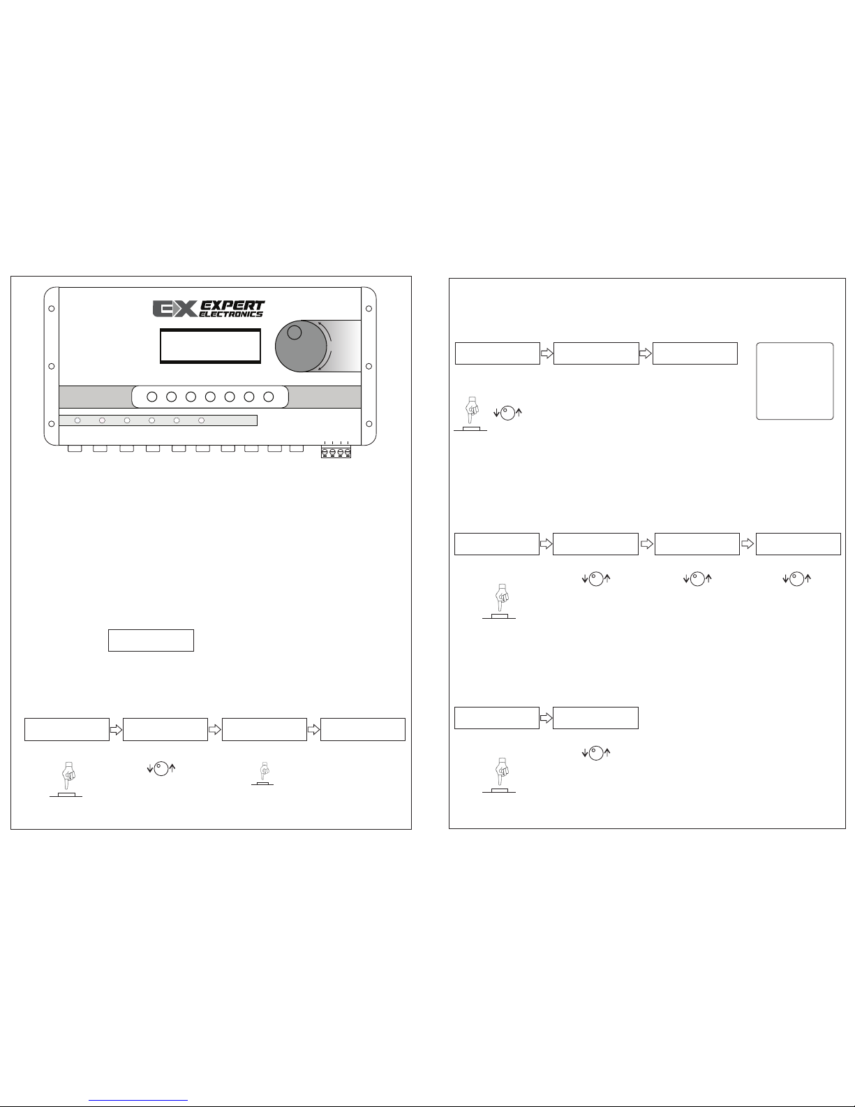
The processor has 8 buttons to configure as the owner wish.
Encoder: Correspond to 28 bands for equalization.
CH: Allow accessing the 6 channels.
ESC: Return to initial display.
Initial display:
1. HOW TO CONFIGURE THE EQUALIZER:
Press the ESC button to go initial display, turn the encoder until EQ IN.
In the display the user can see:
Repeat the 2º and 3º
steps to configure
other 27 frequencies.
The gain level has
steps of 1dB and
limited between -12dB
and 12dB.
Press the Encoder to
change the equalizer’s
frequency.
2. HOW TO CONFIGURE THE PRESETS (CUSTOM1, CUSTOM2, CUSTOM3):
Press ESC to go initial display and then turn or press the encoder until
CROSS/EQ/LIM/ALL CUSTOM, the user can see:
Press or turn the
encoder.
See the display
changed to next user’s
definition (CUSTOM2),
now the user can
configure a new preset
that will be saved in
memory selected.
For accessing the next
memory, repeat the
first and second steps.
OBS: the user’s
definitions save
others
configurations
changed on
processor, and
not just the
equalizer.
3. HOW TO EQUALIZER CHANNELS (CH1, CH2 , CH3, CH4, CH5 CH6):
Press the ESC button to go initial display.
Turn the Encoder until the EQ CH function.
Press the CH to be
equalized.
Press the Encoder to
choose the Q (quality)
factor.
Press the Encoder to
choose the level gain.
Turn up or down the
gain level. Repeat the
steps 2, 3 and 4 to
configure the others
ones.
4. HOW TO CONFIGURE THE CHANNELS:
Press the ESC button to go initial display.
Turn the Encoder until the Routing Channel function:
Press to choose the
channel to be routing.
Choose L, R or L+R
(mono). Press ESC to
go back, choose the
next channel and
repeat the 1 and 2
steps or choose the
function.
Configuration and installation processor guide Configuration and installation processor guide
EQ IN
Freq: 31Hz
G: 0dB=>
Press the Encoder.
1º Step: 2º Step: 3º Step:
Turn the Encoder:
Press the Encoder:
4º Step:
CROSS/EQ/LIM/ALL
CUSTOM
1º Step: 2º Step: 3º Step:
EQUALIZER
CUSTOM 1
EQUALIZER
CUSTOM 2
EQ CH
F1: 500 Hz
1º Step: Channels 2º Step: Choose the freq
1
3
4
EXPERT
ELECTRONICS
Turn the Encoder:
:
Channel
Routing
OUT
CH1: R
1º Step: Channels 2º Step: Choose the Input
Turn the Encoder:
Q1: 2.0
3º Step: Choose the Q
Turn the Encoder:
G1: 0 dB
4º Step: Choose the Gain
Turn the Encoder:
Freq: 40Hz
=>G: 0dB
GND
+12V
REM IN
LIMITER
FUNC
Ch6 Ch5 Ch4 Ch3 Ch2 Ch1 IN L IN R L R
Ch6 Ch5 Ch4 Ch3 Ch2 Ch1 ESC
PX- 2
REM OUT
EXPERT
ELECTRONICS
OUT
6 CH
46 - EQ
Freq: 63Hz
=>G: 0dB
Page 3
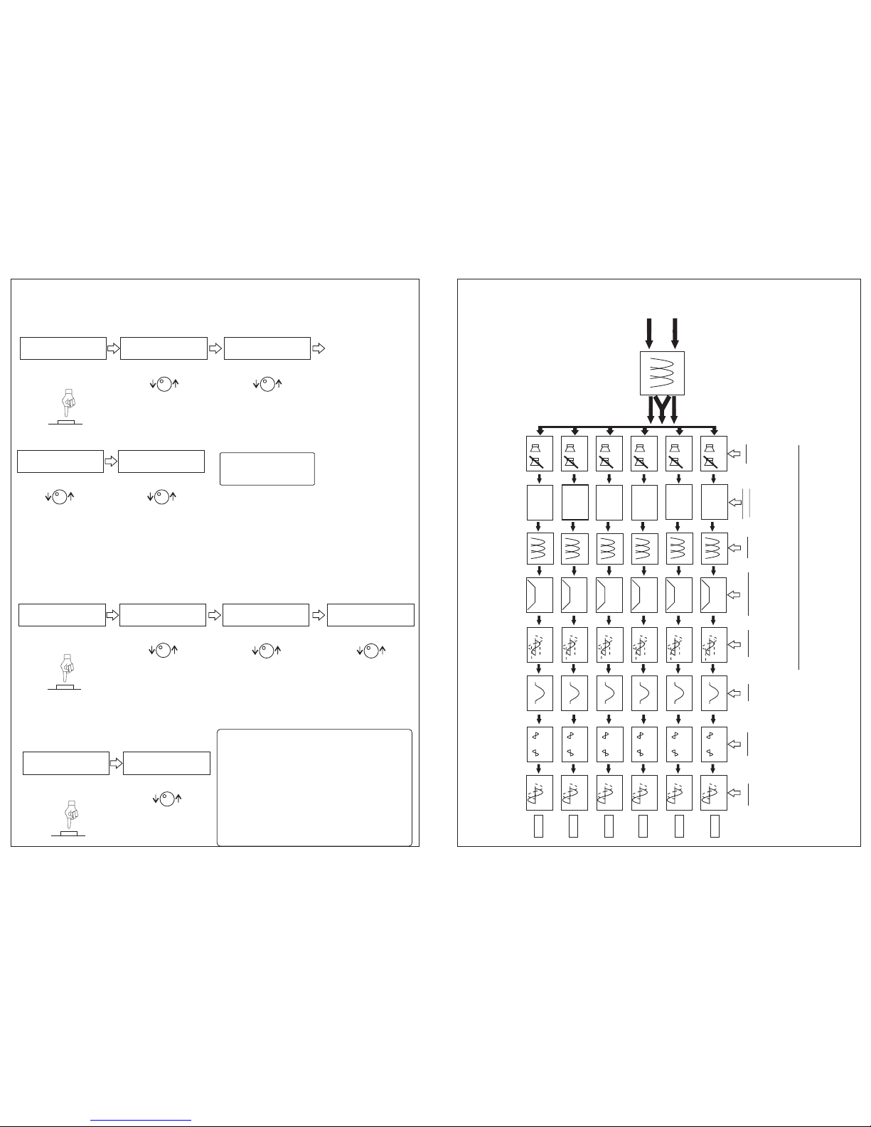
5. HOW TO CONFIGURE THE CROSSOVER:
Press the ESC button to go initial display.
Turn the Encoder until the Crossover function.
Press the encoder to
choose the attenuation.
Choose the
attenuation, Press the
Encoder to go to Low
Pass filter.
Choose the frequency.
Press the Encoder to
choose attenuation.
Choose the
attenuation. Press
ESC to go back at
previous function.
Repeat the steps 1, 2, 3,
4 and 5 to configure
others ones.
6. LIMITER Ch1, Ch2, Ch3, Ch4, Ch5, Ch6):
Press the ESC button to go initial display.
Turn the Encoder until the Limiter function:
Press the channel to
configure:
Choose the Threshold
value. Press the
Encoder to choose the
Attack.
Choose the Attack
value. Press the
Encoder to go Decay.
Choose the release.
Press the ESC button
to go back previous
function.
7. GAIN (Ch1, Ch2, Ch3, Ch4, Ch5, CH6):
Press the ESC button to go initial display.
Turn the Encoder until the Gain function:
Choose and press the
CH button to configure.
Choose the gain. Press
ESC button to go back.
The Reset button when pressed, for a certain
time, returns to factory configurations,
memories and parameters.
For use the Reset function, keep pressed the
Reset button until restart the PX-2.
ALWAYS DISCCONECT THE REMOTE
BEFORE USING THE RESET FUNCTION.
L / R
L+R
L / R
L+R
L / R
L+R
L / R
L+R
L / R
L+R
L / R
L+R
ROUTING
CHANNEL
IN L
IN R
EQ
28 Bandas
CH1
CROSSOVER
CH2
CH3
CH4
CH1
GAIN
CH1
PHASE
0º 180º
CH2
0º 180º
CH3
0º 180º
CH4
0º 180º
CH2
CH3
CH4
CH1
DELAY
CH2
CH3
CH4
OUT 1
-12dB +12dB
6 Vpp máx
12 Vpp máx.
CH1
LIMITER
CH2
CH3
CH4
CH1 =>HPF: 500 Hz
ATEN:12 dB/8
2º Step: freq HP
Turn the Encoder:
3º Step: Choose the attenuation
Turn the Encoder:
CH1 HPF: 500 Hz
=> ATEN:12 dB/8
5º Step: Choose the attenuation
Turn the Encoder:
CH1 LPF: 2000 Hz
=> ATEN:12 dB/8
2º Step: TRESHOLD
Turn the Encoder:
3º Step: Attack
Turn the Encoder:
CH1>T: 0 dB
A:45ms D:12 dB/s
CH1>A: 45 ms
D:12dB/s T:0 dB
4º Step: Decay (release)
Turn the Encoder:
CH1>D: 12 dB/s
T:0dB A:45ms
2º Step: Distance
Turn the Encoder:
CH1>GAIN: 06 dB
CH5
CH6
CH5
0º 180º
CH6
0º 180º
CH5
CH6
CH5
CH6
-18 dB +6dB
0 - 10 ms
CH5
CH6
-24 a 0dB
EQ
-12dB +12dB
EQ
EQ
EQ
EQ
EQ
EQ CH
OUT 2
OUT 3
OUT 4
OUT 5
OUT 6
CH1
MUTE
CH2
CH3
CH4
CH5
CH6
OFF - ON
1
5
2
FUNCTIONAL DIAGRAM
CROSSOVER
1º Step: Filters
Press the channel to
configure:
4º Step: freq LP
CH1 =>LPF: 20000 Hz
ATEN:12 dB/8
Turn the Encoder:
LIMITER
1º Step: LIMITER
GAIN
1º Step: Delay
RESET
Configuration and installation processor guide Configuration and installation processor guide
Page 4
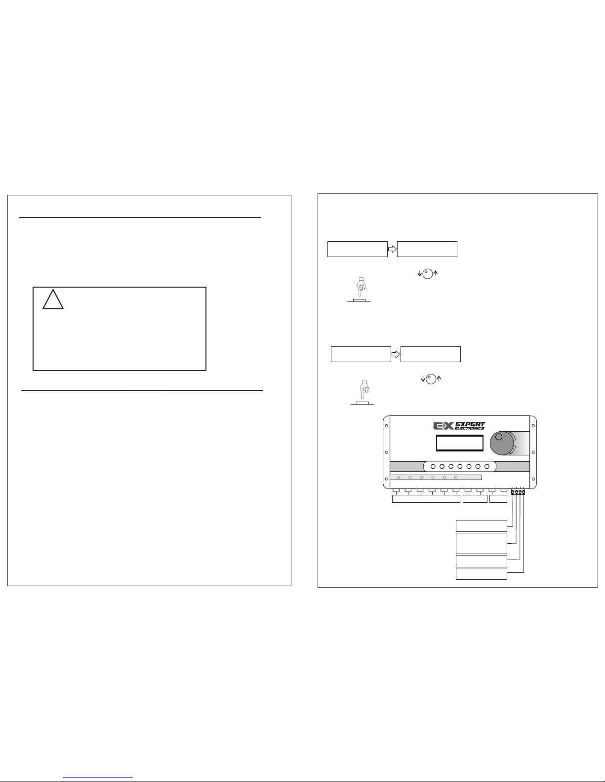
8. PHASE:
Press the ESC button to go initial display.
Turn the Encoder until the Phase function
Press the channel to
configure:
Choose the phase 0 or
180. Press ESC button
to return.
Press the channel to
configure:
Choose the distance.
Press ESC to return.
Remote from player
connect to remote
input the processor
Remote output
connect to amplifiers
Positive/Supply
(10~15v)
9. DELAY:
Press the ESC to go initial display.
Turn the ESC button to go initial display.
- The installation may be done in covered local,
ventilated and no vibration. Install the device in
adequate local.
- Please, protect the LCD out of direct solar
radiation, covered and ventilated.
- The recommendations above guarantee the correct
function of the system.
1
1
INDEX
Functional Diagram..............................
Step by step configuration..................
Installation............................................
02
03-05
06
Caution:
!
Technical Especifications
Frequency response.....................
Equalização (Frequencies)...........
Equalização (Gain).......................
HIPASS Filter................................
LOWPASS Filter...........................
Attenuation Filter............................
MUTE............................................
Gain..............................................
Phase...........................................
Delay.............................................
Input Sensitivy..............................
Output Signal. ...............................
Input impedance...........................
Output impedance.........................
ADC SNR......................................
DAC SNR......................................
THD + N........................................
Resolution.....................................
Frequency Sample........................
Dimensions....................................
Weight...........................................
20 Hz - 20 KHz (com filtro ativo)
-12dB / +12dB
20 Hz - 20 KHz
(31,40,50,63,80,100,125,160,200,250,315,
400,500,630,800,1000,1250,1600,2000,2500,
3150,4000,5000,6300,8000,10000,12500,16000)
20 HZ - 20 KHz
6 / 12 / 18 / 24 / 36 / 48 (dB/8º) / OFF
-100 dB
-18dB / 6dB
0º / 180º
399 Samples - 286,7cm
0,1 - 4 Vpp
0 - 8 Vpp
47 KOhm
100 Ohm
100 dB
104 dB
0.02%
24 Bit
48 KHz
120 x 250 x 30mm
0,42 Kg - 0,92 Lb
PHASE
1º Step: PHASE 2º Step: 0º ou 180º
Turn the Encoder:
CH1>PHASE: 0
DELAY
1º Step: Delay 2º Step: Distance
Turn the Encoder:
CH1>DELAY: 1 sample
0007 mm
GND
+12V
REM IN
LIMITER
FUNC
Ch6 Ch5 Ch4 Ch3 Ch2 Ch1 IN L IN R L R
Ch6 Ch5 Ch4 Ch3 Ch2 Ch1 ESC
PX- 2
REM OUT
EXPERT
ELECTRONICS
OUT
6 CH
46 - EQ
Amplifier’s CHannels
6
Negative/Ground
PLAYER LINK
Configuration and installation processor guide Configuration and installation processor guide
 Loading...