

Page 1

1
1. Introduction
EX-9017 series is a analog input module with 8 input channels. It
can select 8 channels all are differential type or 6 of the eight
channels are differential & other two are single ended type.
Specifications:
Interface: RS-485, 2 wires
Speed (bps): 1200, 2400, 4800, 9600, 19.2K, 38.4K, 15.2K
Analog Input type: 8 differential/ 6 differential & 2 single ended
Analog Channels Numbers: 8
Analog Resolution:16 bits (12bits for 9017F series)
Unit Conversion:
+/-10V,+/-5V,+/-1V,+/-500mV,+/-150mV,+/-20mA
Sampling Rate :10 Samples/Second
Bandwidth : 15.7 Hz
Accuracy : ±0.1%
Zero Drift : 0.5µV/°C
Span Drift : 25ppm/°C
CMR@50/60Hz : 150dB
NMR@50/60Hz : 100dB
Input Impedance : 20M Ohms
Current Measurement: ±20mA (with external 125 ohms resistor)
Power supply: +10V to +30V
Page 2

2
Page 3

3
Specifications
EX-9017F EX-9017R EX-9017FR
Interface
RS-485, 2 wires
Speed(bps)
1200, 2400, 4800, 9600, 19200, 38400, 57600, 115200
Analog Input type
6 differential input & 2 single ended input
Input Channels
8
Resolution
16/12 bits 16 bits 16/12 bits
Voltage Input
-10V ~ +10V
-5V ~ +5V
-1V ~ +1V
-500mV ~ +500mV
-150mV ~ +150mV
Current Input
-20mA ~ +20mA (with 125ohms resistor)
Sampling Rate
10/50Hz 10Hz 10/50Hz
Bandwidth
15.7Hz
Accuracy
±0.1%
Zero Drift
0.5µV/°C
Span Drift
25ppm/°C
CMR@50/60Hz
150dB
NMR@50/60Hz
100dB
Input Impedance
20M ohms
Power supply
+10V ~ +30V
Over voltage protection
Not support 240Vrms
Notes:
1. Warm-UP for 30 minutes is recommended before starting operation!
2. EX-9017F: EX-9017 w/ fast mode (12bits)
3. EX-9017FR: EX-9017 w/ fast mode (12bits) & 240Vrms over voltage protection
Page 4

4
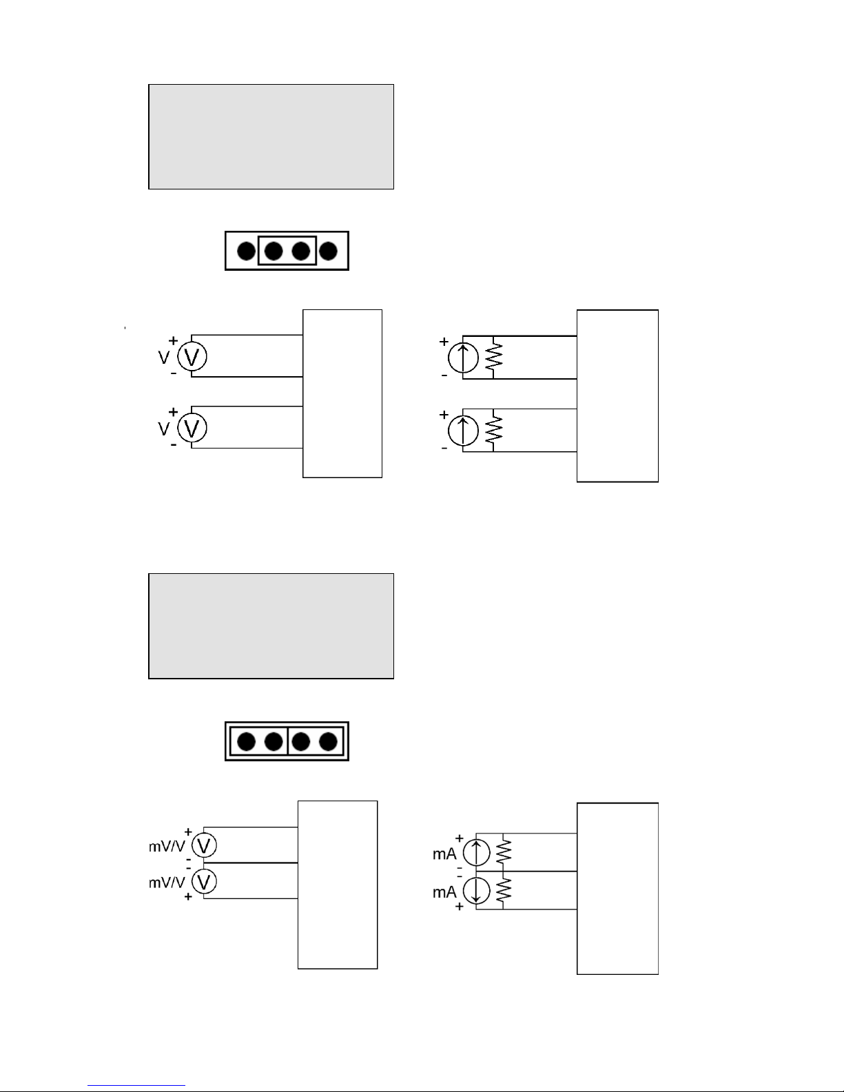
EX9017F Analog I/P Channel 0
to 5 wire connection
1.2 Wire connection
1.2.1 Block Diagrams
1.2.2 Wiring diagram for the EX-9017 series
EEPROM
Single
Controller
RS485
Interface
Power
Supply
+5V
ADC
Vin 6-
Vin 0+
EX9017
Data+
Data-
+Vs
GND
Vin 7Vin 6+
Vin 0-
Photo-Isolation
MUX
Vin 1-
Vin 1+
Vin 7+
mV/V
+Vinx
+Vinx
mA
+Vinx
-
V
inx
Page 5
5
EX9017/17F Analog I/P Channel
6 and 7 wire connection, while
the jumper JP1 setting is 8
differential mode.
EX9017F Analog I/P Channel 6
and 7 wire connection, while the
jumper JP1 setting is Init* mode.
JP1
JP1
Vin6+
Vin6Vin7+
INIT/Vin7-
JP1
Vin6+
Vin6Vin7+
INIT/Vin7-
Vin6+
Vin6Vin7+
INIT/Vin7-
Vin6+
Vin6Vin7+
INIT/Vin7-
mA
mA
Page 6

6
1.3 Default Settings
Default settings for the EX-9017/17F/17R/17FR modules are as
follows:
. Module Address: 01
. Analog Input Type: type 05
. Baud Rate: 9600 bps
. Checksum disabled
. Engineering unit format
. Filter set at 60Hz rejection
Page 7
7
1.4 INIT* Mode Operation
Each EX9000 module has a build-in EEPROM to store configuration
information such as address, type, baudrate and other information.
Sometimes, user may forget the configuration of the module. Therefore,
the EX9000 have a special mode named "INIT* mode" to help user to
resolve the problem. The "INIT* mode" is setting as Address=00,
Budrate=9600bps, no Checksum .
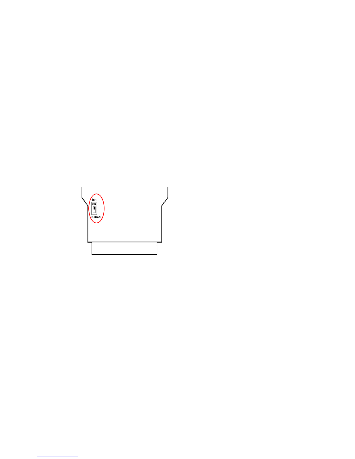
Originally, the INIT* mode is accessed by connecting the INIT* terminal
to the GND terminal. New EX9000 modules have the INIT* switch
located on the rear side of the module to allow easier access to the INIT*
mode. For these modules, INIT* mode is accessed by sliding the INIT*
switch to the Init position as shown below.
To enable INIT* mode, please following these steps:
Step1. Power off the module
Step2. Connect the INIT* pin with the GND pin.
(or sliding the INIT* switch to the Init* ON position)
Step3. Power on
Step4. Send command $002 (cr) in 9600bps to read the
Configuration stored in the module's EEPROM.
There are commands that require the module to be in INIT* mode. They
are:
1. %AANNTTCCFF when changing the Baud Rate and checksum
settings. See Section 2.1 for details.
Page 8

8
1.5 Module Status for DIO, AIO
Power On Reset or Module Watchdog Reset will let all output
goto Power On Value. And the module may accept the host's command
to change the output value.
Host Watchdog Timeout will let all output goto Safe Value. The
module's status(read by command~AA0) will be 04
, and the output
command will be ignored.
1.6
Dual Watchdog Operation for DIO, AIO
Dual Watchdog=Module Watchdog + Host Watchdog
The Module Watchdog
is a hardware reset circuit to monitor the
module's operating status. While working in harsh or noisy environment,
the module may be down by the external signal. The circuit may let the
module to work continues and never halt.
The Host Watchdog
is a software function to monitor the host's
operating status. Its purpose is to prevent the network from
communication problem or host halt. When the timeout interval expired,
the module will turn all outputs to predefined Safe Value. This can
prevent the controlled target from unexpected situation.
The EX9000 module with Dual Watchdog may let the control
system more reliable and stable.
1.7 Reset Status
The Reset Status is set while the module power on or reset by module
watchdog and is cleared while the command read Reset Status ($AA5)
applied. This is useful for user to check the module's working status.
When the Reset Status is set means the module is reset and the output
may be changed to the PowerOn Value. When the Reset Status is clear
means the module is not rested and the output is not changed.
Page 9

9
1.8 Calibration
Calibration Requirement for EX9017 series. While calibrate type 0D, the EX9017
series need connect external shunt resistor, 125Ohms, 0.1%
Type code 08 09 0A 0B 0C 0D
Zero Input 0V 0V 0V 0mV 0mV 0mA
Span +10V +5V +1V +500mV +150mV +20mA
Calibration Sequence:
1. Connect calibration voltage/current to module's channel 0.
2. Warm-Up for 30 minutes
3. Set the input type of module which you wish to calibration.
4. Enable Calibration (P.24)
5. Apply Zero Calibration Voltage
6. Preform Zero Calibration Command (P.16)
7. Apply Span Calibration Voltage
8. Perform Span Calibration Command (P.15)
9. Repeat step4 to step 8 three times.
Warning: Please don't calibrate before you really understand.
Page 10

10
1.9 Configuration Tables
Baud Rate Setting (CC)
Code
03 04 05 06 07 08 09 0A
Baud rate
1200 2400 4800 9600 19200 38400 57600 115200
Sensor Type & V/I Range Setting (TT)
Code Range Format +F.S. Zero -F.S.
Engineer unit +10.000 +00.000 -10.000
% of F.S.R. +100.00 +000.00 -100.00
08 -10~+10V
2’s complement 7FFF 0000 8000
Engineer unit +5.0000 +0.0000 -5.0000
% of F.S.R. +100.00 +000.00 -100.00
09 -5~+5V
2’s complement 7FFF 0000 8000
Engineer unit +1.0000 +0.0000 -1.0000
% of F.S.R. +100.00 +000.00 -100.00
0A -1~+1V
2’s complement 7FFF 0000 8000
Engineer unit +500.00 +000.00 -500.00
% of F.S.R. +100.00 +000.00 -100.00
0B -500~+500mV
2’s complement 7FFF 0000 8000
Engineer unit +150.00 +000.00 -150.00
% of F.S.R. +100.00 +000.00 -100.00
0C -150~+150mV
2’s complement 7FFF 0000 8000
Engineer unit +20.000 +00.000 -20.000
% of F.S.R. +100.00 +000.00 -100.00
0D -20~+20mA
2’s complement 7FFF 0000 8000
Page 11

11
Data Format Setting (FF)
7 6 5 4 3 2 1 0
FS CS reserved DF
Key Description
DF
Data format
00: Engineering unit
01: % of FSR (full scale range)
10: 2’s complement hexadecimal
CS
Checksum setting
0: Disabled
1: Enabled
FS
Filter setting
0: 60Hz rejection
1: 50Hz rejection
Note: The reserved bits should be zero.
Page 12

12
2.0 Command set
2.1 %AANNTTCCFF
Description: Set Module Configuration.
Syntax:
%AANNTTCCFF[CHK](cr)
% a delimiter character
AA address of setting/response module(00 to FF)
NN new address for setting/response module(00 to FF)
TT represents the type code. Type code determines the
input range.
If TT=FF the type of all channels keep no change.
CC new baudrate for setting module.
FF new data format for setting module.
IF the configuration with new baudrate or new checksum setting, before
using this command, the rear slide switch must be in the ON(INIT*)
position. The new setting is saved in the EEPROM and will be effective
after the next power-on reset.
Response: Valid Command: !AA
Invalid Command: ?AA
Example:
Command: %0203080602
Receive: !02
Set module address 02 to 03.
Input type code=08 (-10~+10V) for all channels
Baudrate=06 (9600)
Dataformat=02 (2’s complement hexadecimal)
Page 13

13
2.2 #AA
Description: Read Analog Input
Syntax: #AA[CHK](cr)
# delimiter character
AA address of reading/response module(00 to FF)
Response: Valid Command: >(Data)
(Data) analog input value for its format while use #AA command
to EX9017F, the data is the combination for each channel
respectively.
Example :
Command :#01 Receive : >+02.635
Read address 01, get data successfully.
Command : #02 Receive : >4C53
Read address 02, get data in HEX format successfully.
Command : #04
Receive:>+05.123+04.153+07.234-02.356+10.000-05.133+02.34
5+08.234
The module address 04 is EX9017. Read address 04 for getting
data of all 8 channels.
Page 14

14
2.3 #AAN
Description : Read Analog Input from channel N
Syntax : #AAN[CHK](cr)
# delimiter character
AA address of reading/response module(00 to FF)
N channel to read, from 0 to 7
Response: Valid Command: >(Data)
Invalid Command: ?AA
(Data) analog input value for its format
Example :
Command : #032 Receive : >+025.13
Read address 03 channel 2, get data successfully.
Command : #029 Receive : ?02
Read address 02 channel 9, return error channel number.
Page 15

15
2.4 $AA0
Description: Perform Span Calibration
Syntax: $AA0[CHK](cr)
$ delimiter character
AA address of setting/response module (00 to FF)
0 command for performing zero calibration
Response: Valid Command: !AA
Invalid Command: ?AA
Example :
Command : $010 Receive : !01
Perform address 01 zero calibration on channel 0, return success.
Command : $020 Receive : ?02
Perform address 02 zero calibration on channel 2 , return not
enable calibration before perform calibration command.
Warning: Pls don't calibrate before you really understand.
Page 16

16
2.5 $AA1
Description: Perform Zero Calibration
Syntax: $AA1[CHK](cr)
$ delimiter character
AA address of setting/response module (00 to FF)
1 command for performing span calibration
Response: Valid Command: !AA
Invalid Command: ?AA
Example:
Command: $011 Receive: !01
Perform address 01 span calibration on channel 0, return success.
Command: $021 Receive: ?02
Perform address 02 span calibration on channel 2, return not
enable calibration before perform calibration command.
Warning: Pls don't calibrate before you really understand.
Page 17

17
2.6 $AA2
Description: Read configuration.
Syntax: $AA2[CHK](cr)
$ delimiter character
AA address of reading/response module (00 to FF)
2 command for read configuration
Response:
Valid Command: !AATTCCFF
Invalid Command: ?AA
TT type code of module
CC baudrate code of module
FF data format of module
Example:
Command: $012 Receive: !01080600
Read the configuration of module 01, input range of -10~+10V,
baudrate 9600, no checksum.
Note: check configuration Tables
Page 18

18
2.7 $AA5VV
Description: Set Channel Enable
Syntax: $AA5VV[CHK](cr)
$ delimiter character
AA address of setting/response module (00 to FF)
5 command for set channel enable
VV are two hexadecimal values. The values are interpreted by
the module as two binary words (4-bit). The first word
represents the status of channel 4~7, and the second word
represents the status of channel 0~3. Value 0 means the
channel is disabled, value 1 means the channel is enabled.
Response: Valid Command: !AA
Invalid Command: ?AA
Example:
Command :$0152A Receive : !01
Set address 01 to enable channel 1,3,5 and disable channel
0,2,4,6,7 return success.
Command : $016 Receive : !012A
Read address 01 channel status, return channel 1,3,5 are
enabled and channel 0,2,4,6,7 are disabled.
Page 19

19
2.8 $AA6
Description: Read Channel Status
Syntax: $AA6[CHK](cr)
$ delimiter character
AA address of reading/response module (00 to FF)
6 command for read channel status
Response: Valid Command: !AAVV
Invalid Command: ?AA
VV are two hexadecimal values. The values are interpreted by
the module as two binary words (4-bit). The first word
represents the status of channel 4~7, and the second word
represents the status of channel 0~3. Value 0 means the
channel is disabled, value 1 means the channel is enabled.
Example:
Command :$0152A Receive : !01
Set address 01 to enable channel 1,3,5 and disable channel
0,2,4,6,7 return success.
Command : $016 Receive : !012A
Reads Read address 01 channel status, return channel 1,3,5 are
enabled and channel 0,2,4,6,7 are disabled.
Page 20

20
2.9 $AAF
Description: Read Firmware Version
Syntax: $AAF[CHK](cr)
$ delimiter character
AA address of reading/response module(00 to FF)
F command for read firmware version
Response: Valid command: !AA(Data)
Invalid command: ?AA
(Data) Firmware version of module
Example:
Command : $01F Receive : !01M6.92
Read address 01 firmware version, return version M6.92
Page 21

21
2.10 $AAM
Description: Read Module Name
Syntax: $AAM[CHK](cr)
$ delimiter character
AA address of reading/response module(00 to FF)
M command for read module name
Response: Valid command: !AA(Data)
Invalid command: ?AA
(Data) Name of module
Example:
Command : $01M Receive : !019017
Read address 01 module name, return name 9017.
Page 22

22
2.11 ~AAEV
Description: Enable/Disable Calibration
Syntax: ~AAEV[CHK](CR)
~ delimiter character
AA address of setting/response module (00 to FF)
E command for enable/disable calibration
V 1=Enable/0=Disable calibration
Response: Valid Command: !AA
Invalid Command: ?AA
Example:
Command : $010 Receive: ?01
Perform address 01 span calibration, return the command is
invalid before enable calibration.
Command : ~01E1 Receive: !01
Set address 01 to enable calibration, return success.
Command: $010 Receive: !01
Preform address 01 span calibration, return success.
Warning: Pls don't calibrate before you really understand.
Page 23

23
2.12 ~AAO(Data)
Description: Set Module Name
Syntax: ~AAO(Data)[CHK](cr)
~ delimiter character
AA address of setting/response module(00 to FF)
O command for set module name
(Data) new name for module, max 6 characters
Response: Valid command: !AA
Invalid command: ?AA
Example:
Command:~01O9017 Receive :!01
Set address 01 module name 9017, return success.
Page 24

24
2.13 ~**
Description: Host OK.
Host send this command to all modules for send the information
"Host OK"
Syntax: ~**[CHK](cr)
~ delimiter character
** command for all modules
Response: No response.
Example:
Command: ~** No response
Page 25

25
2.14 ~AA0
Description: Read Module Host Watchdog Status.
Syntax: ~AA0[CHK](cr)
~ delimiter character
AA address of reading/response module(00 to FF)
0 command for read module status
Response: Valid command: !AASS
Invalid command: ?AA
SS module status, 00=host watchdog timeout status is
clear,04=host watchdog timeout status is set. The status
will store into EEPROM and only may reset by the
command~AA1.
Page 26

26
2.15 ~AA1
Description: Reset Module Host Watchdog Status.
Syntax: ~AA1[CHK](cr)
~ delimiter character
AA address of setting/response module(00 to FF)
1 command for reset module status
Response: Valid command: !AA
Invalid command: ?AA
Page 27

27
2.16 ~AA2
Description: Read Host Watchdog Timeout Value
Syntax: ~AA2[CHK](cr)
~ delimiter character
AA address of reading/response module(00 to FF)
2 command for read host watchdog timeout value
Response: Valid command : !AAEVV
Invalid command: ?AA
E host watchdog enable status, 1=Enable, 0=Disable
VV timeout value in HEX format, each count is 0.1
second
01=0.1 second and FF=25.5 seconds
Page 28

28
2.17 ~AA3EVV
Description: Set Host Watchdog Timeout Value
Syntax: ~AA3EVV[CHK](cr)
~ delimiter character
AA address of setting/response module(00 to FF)
3 command for set host watchdog timeout value
E 1=Enable/0=Disable host watchdog
VV timeout value, from 01 to FF, each for 0.1 second
Response: Valid command: !AA
Invalid command: ?AA
Example:
Command : ~010 Receive : !0100
Read address 01 modules status, return host watchdog
timeout status is clear.
Command : ~013164 Receive : !01
Set address 01 host watchdog timeout value 10.0 seconds
and enable host watchdog, return success.
Command : ~012 Receive : !01164
Read address 01 host watchdog timeout value, return that
host watchdog is enabled, and time interval is 10.0 seconds.
Command : ~** No response
Reset the host watchdog timer.
Wait for about 10 seconds and don't send command~**, the
LED of module will go to flash. The flash LED indicates the
host watchdog timeout status is set.
Command : ~010 Receive : !0104
Page 29

29
Read address 01 module status, return host watchdog
timeout status is set.
Command : ~012 Receive : !01064
Read address 01 host watchdog timeout value, return that
host watchdog is disabled, and time interval is 10.0 seconds.
Command : ~011 Receive : !01
Reset address 01 host watchdog timeout status, return
success And the LED of this module stop flash.
Command : ~010 Receive : !0100
Read address 01 module status, return host watchdog
timeout status is clear.
 Loading...