

Page 1
1
1. Introduction
The common features of the EX-9016 modules is as follows:
1. 3000 VDC isolatied analog input.
2. 24-bits sigma-delta ADC to provide excellent accuracy.
3. 16-bit DAC supply excitation voltage for strain gauge.
4. Software calibration.
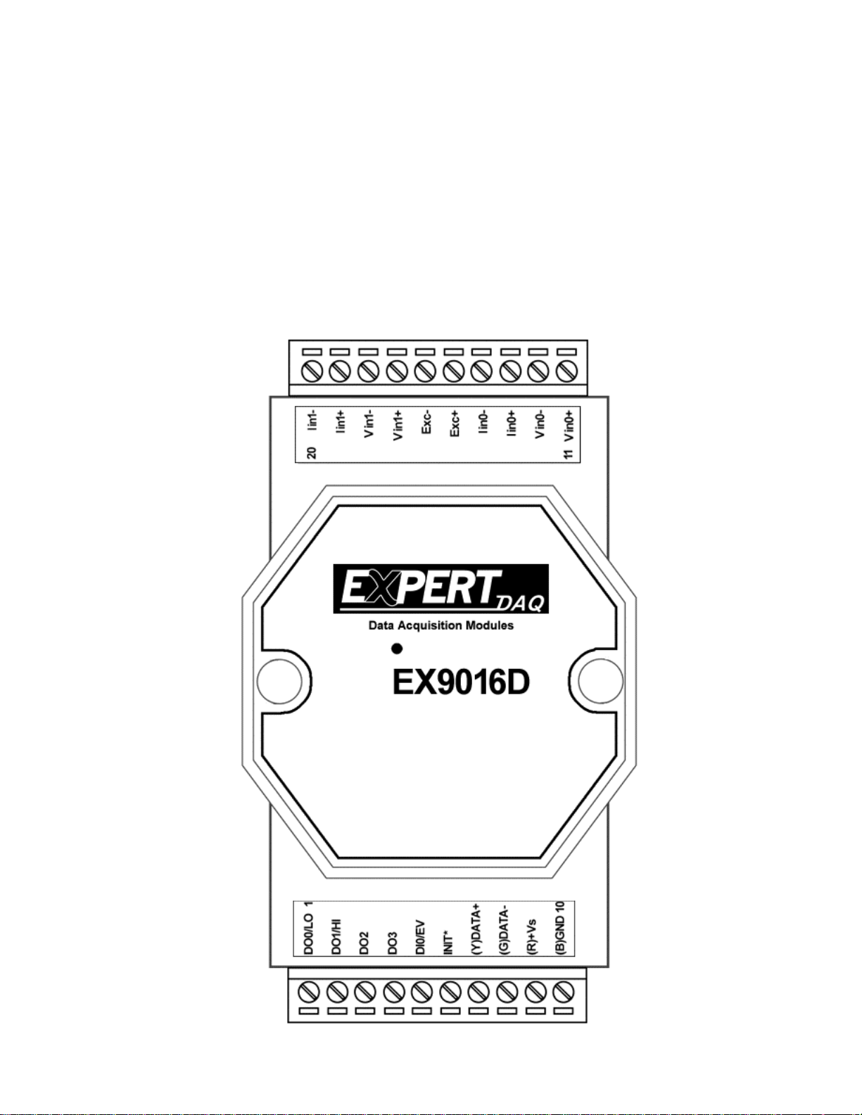
5. EX9016D is the EX9016 with 7-segment LED Display.
Page 2

2
1.1 Specifications
Analog Input
Input Channels
2
Analog Input Type
mV, V, mA
Sampling Rate
10 Samples/Second
Bandwidth
5.25Hz
Accuracy
±0.05%
Zero Drift
0.5µV/℃
Span Drift
25ppm/℃
CMR@50/60Hz
150dB
NMR@50/60Hz
100dB
Input Impedance
20M Ohms
Isolation
3000VDC
Excitation Voltage Output
Output Channel
1
Output Range
0 to +10V
Max Output Load
40mA
Accuracy
±0.05% of FSR
Drift
±50ppm/℃
Output Impedance
12Ohms
Isolation
3000VDC
Digital Output
Output channels
4
Output Type
Open Collector to 30V
Output Load
Sink 30mA max
Power Dissipation
300mW
Digital Input
Input Channel
1
Digital Level 0
+1V Max
Digital Level 1
+3.5~+30V Max
Event Counter
Max Input Frequency
50Hz
Min Pulse Width
1mS
Environment
Power Requirement
+10 to +30 VDC
Power Consumption
2.4 W
Operating Temperature
-25°C to +75°C
Storage Temperature
-30°C to +75°C
Notes: Warm-UP for 30 minutes is recommended!
Page 3

3
Led
Display
EEPROM
Single
Controller
RS485
Interface
Power
Supply
+5V
DI0/EV
Exc+
EX9016D
Data+
Data-
+Vs
GND
Iin0+
Photo-Isolation
ADC
Iin1-
Vin1+
DO1/HI
DO3
Vin1-
Vin0-
MUX
Photo-Isolation
DAC
buffer
DO0/LO
DO2
Iin0-
Vin0+
Iin1+
Exc-
1.2 Wire connection
1.2.1 Block Diagrams
Page 4
4
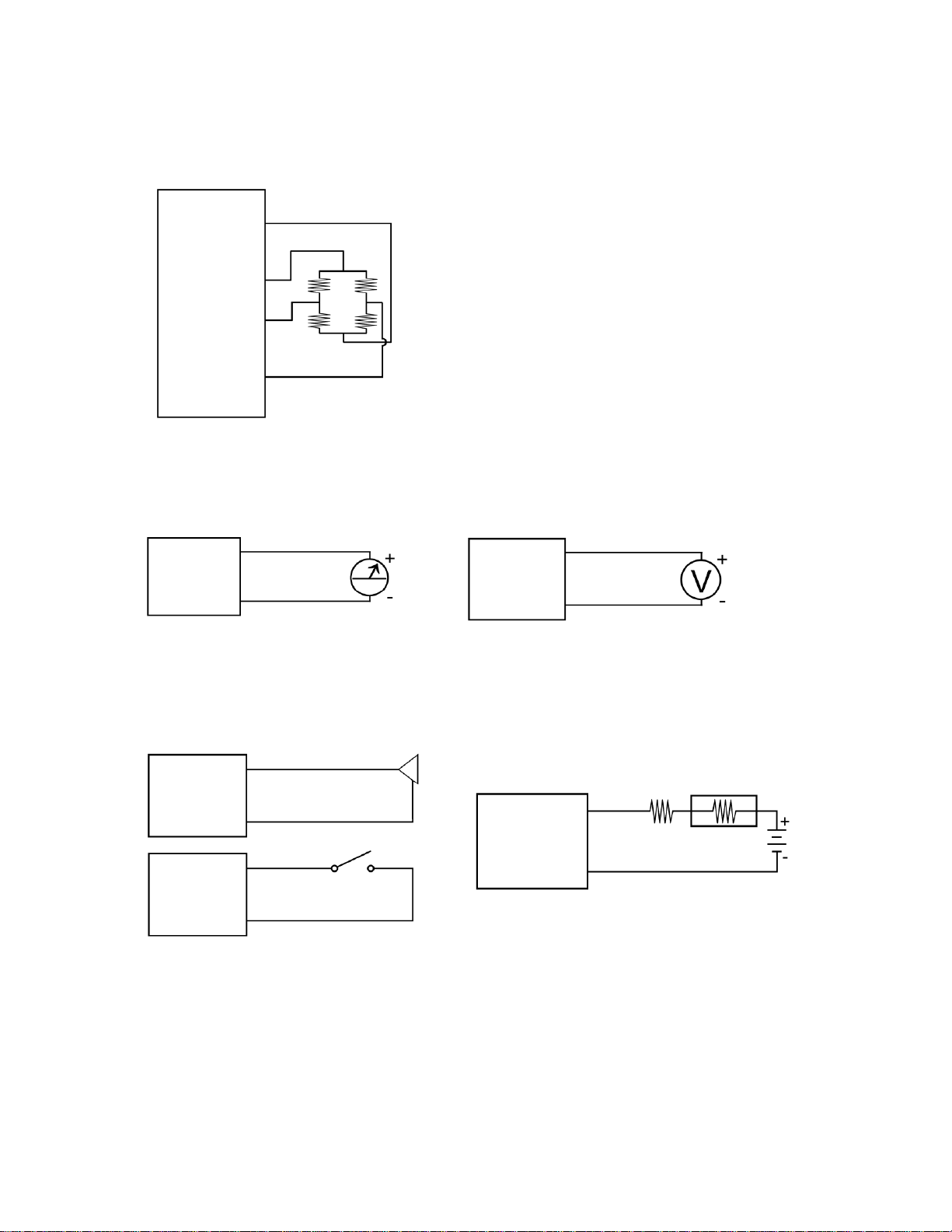
1.2.2 Wiring diagram for the EX-9016
EXC-
EXC+
Vin-
Vin+
EXC+
EXC-
V
Vin-
Vin+
mV/V
DI0/EV
GND
DI0/EV
GND
TTL.GND
DOx
GND
Bridge Sensor/Load Cell/Strain Gauge Wire Connection
Analog Input Wire Connection: Analog Output Wire Connection:
Digital Input Wire Connection: Digital Output Wire Connection:
Page 5

5
1.3 Default Settings
Default settings for the EX-9016 module are as follows:
. Module Address: 01
. Analog Input Type: Type 05, -2.5 to +2.5V
. Baud Rate: 9600 bps
. Checksum disabled
. Engineering unit format
. Filter set at 60Hz rejection
Page 6
6
1.4 INIT* Mode Operation
Each EX9000 module has a build-in EEPROM to store configuration
information such as address, type, baudrate and other information.
Sometimes, user may forget the configuration of the module. Therefore,
the EX9000 have a special mode named "INIT* mode" to help user to
resolve the problem. The "INIT* mode" is setting as Address=00,
Budrate=9600bps, no Checksum .
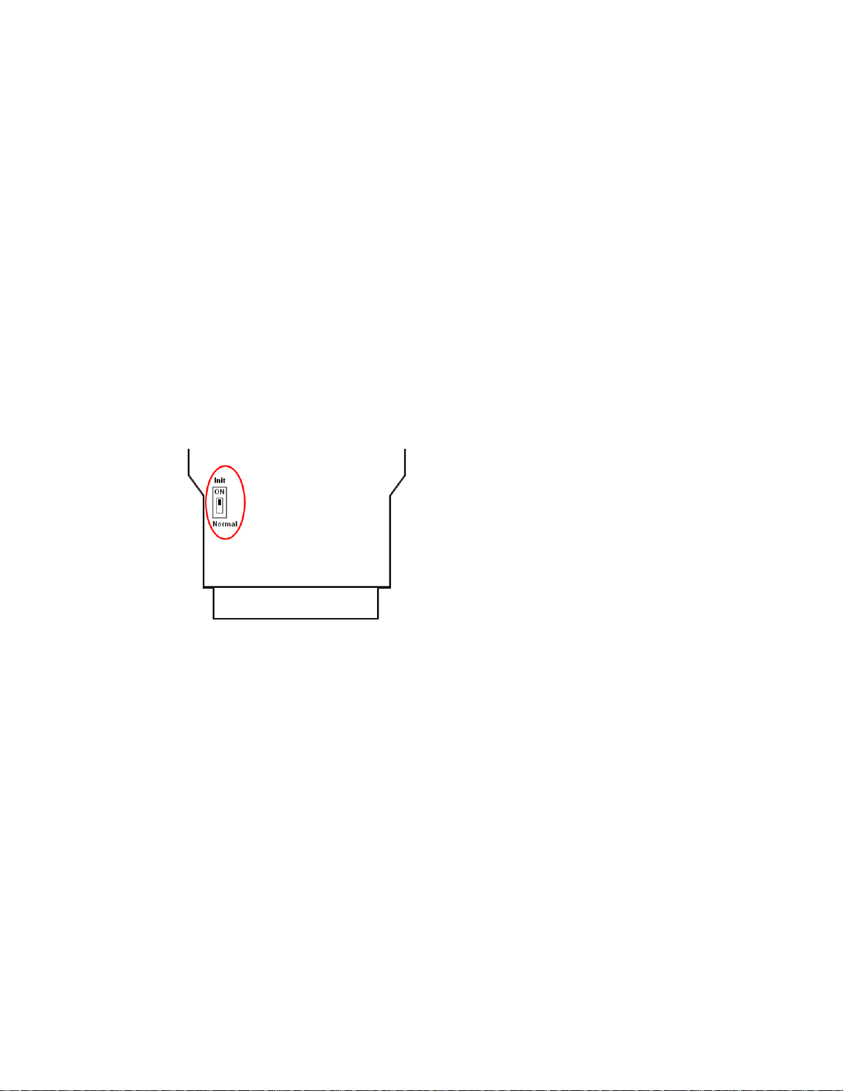
Originally, the INIT* mode is accessed by connecting the INIT*
terminal to the GND terminal. New EX9000 modules have the INIT*
switch located on the rear side of the module to allow easier access to
the INIT* mode. For these modules, INIT* mode is accessed by sliding
the INIT* switch to the Init position as shown below.
To enable INIT* mode, please following these steps:
Step1. Power off the module
Step2. Connect the INIT* pin with the GND pin.
(or sliding the INIT* switch to the Init* ON position)
Step3. Power on
Step4. Send command $002 (cr) in 9600bps to read the
Configuration stored in the module's EEPROM.
There are commands that require the module to be in INIT* mode.
They are:
1. %AANNTTCCFF when changing the Baud Rate and checksum
settings. See Section 2.1 for details.
Page 7

7
1.5 Module Status for DIO, AIO
Power On Reset or Module Watchdog Reset will let all
output goto Power On Value. And the module may accept the host's
command to change the output value.
Host Watchdog Timeout will let all output goto Safe Value.
The module's status(read by command~AA0) will be 04, and the output
command will be ignored.
1.6
Dual Watchdog=Module Watchdog + Host Watchdog
module's operating status. While working in harsh or noisy
environment, the module may be down by the external signal. The
circuit may let the module to work continues and never halt.
operating status. Its purpose is to prevent the network from
communication problem or host halt. When the timeout interval expired,
the module will turn all outputs to predefined Safe Value. This can
prevent the controlled target from unexpected situation.
system more reliable and stable.
Dual Watchdog Operation for DIO, AIO
The Module Watchdog is a hardware reset circuit to monitor the
The Host Watchdog is a software function to monitor the host's
The EX9000 module with Dual Watchdog may let the control
1.7 Reset Status
The Reset Status is set while the module power on or reset by module
watchdog and is cleared while the command read Reset Status ($AA5)
applied. This is useful for user to check the module's working status.
When the Reset Status is set means the module is reset and the output
may be changed to the PowerOn Value. When the Reset Status is clear
means the module is not rested and the output is not changed.
Page 8

8
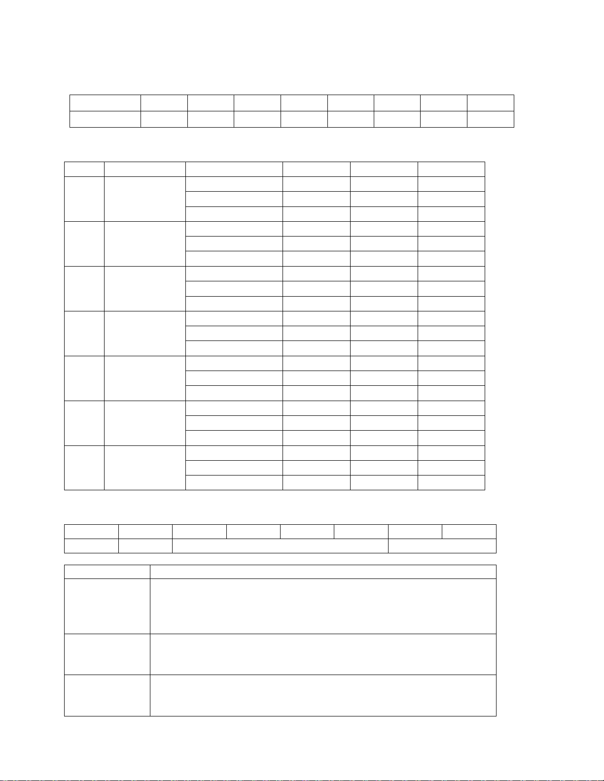
1.8 Calibration(Warning: Pls don't calibrate before you
Type code
00
01
02
03
04
05
06
Zero Input
0mV
0mV
0mV
0mV
0V
0V
0mA
Span Input
+15mV
+50mV
+100mV
+500mV
+1V
+2.5V
+20mA
really understand.)
Analog Input Calibration sequence:
1. Apply zero calibration voltage.
2. Warm up the module for at least 30 minutes.
3. Set the type code to the type you wish to calibrate.
4. Enable calibration. -> Ref Sec.2.16
5. Perform zero calibration command. -> Ref Sec.2.5
6. Apply span calibration voltage.
7. Perform span calibration command. -> Ref Sec.2.4
8. Repeat steps 4 to 7 three times.
Excitation Voltage Calibration sequence:
1 Connect voltmeter to module’s excitation output pin.
2 Warm-Up for 30 minutes.
3 Output 0V. -> Ref Sec.2.18
4 Trim the output until the value in voltmeter is closest to 0V.
-> Ref Sec.2.20
5 Perform Excitation Voltage Zero Calibration. -> Ref Sec.2.21
6 Output 10V. -> Ref Sec.2.18
7 Trim the output until the value in voltmeter is closest to 10V.
-> Ref Sec.2.20
8 Perform Excitation Voltage Span Calibration. -> Ref Sec.2.22
Page 9
9
1.9 Configuration Tables
Code
03
04
05
06
07
08
09
0A
Baud rate
1200
2400
4800
9600
19200
38400
57600
115200
Code
Range
Format
+F.S.
Zero
-F.S.
00
-15~+15mV
Engineer unit
+15.000
+00.000
-15.000
% of F.S.R.
+100.00
+000.00
-100.00
2’s complement
7FFF
0000
8000
01
-50~+50mV
Engineer unit
+50.000
+00.000
-50.000
% of F.S.R.
+100.00
+000.00
-100.00
2’s complement
7FFF
0000
8000
02
-100~+100mV
Engineer unit
+100.00
+000.00
-100.00
% of F.S.R.
+100.00
+000.00
-100.00
2’s complement
7FFF
0000
8000
03
-500~+500mV
Engineer unit
+500.00
+000.00
-500.00
% of F.S.R.
+100.00
+000.00
-100.00
2’s complement
7FFF
0000
8000
04
-1~+1V
Engineer unit
+1.0000
+0.0000
-1.0000
% of F.S.R.
+100.00
+000.00
-100.00
2’s complement
7FFF
0000
8000
05
-2.5~+2.5V
Engineer unit
+2.5000
+0.0000
-2.5000
% of F.S.R.
+100.00
+000.00
-100.00
2’s complement
7FFF
0000
8000
06
-20~+20mA
Engineer unit
+20.000
+00.000
-20.000
% of F.S.R.
+100.00
+000.00
-100.00
2’s complement
7FFF
0000
8000
7 6 5 4 3 2 1
0
FS
CS
reserved
DF
Key
Description
DF
Data format
00: Engineering unit
01: % of FSR (full scale range)
10: 2’s complement hexadecimal
CS
Checksum setting
0: Disabled
1: Enabled
FS
Filter setting
0: 60Hz rejection
1: 50Hz rejection
Baud Rate Setting (CC)
Analog Input Type Setting (TT)
Data Format Setting (FF)
Note: The reserved bits should be zero.
Page 10

10
2 Command
General Command Sets
Command
Response
Description
Section
%AANNTTCCFF
!AA
Set Module Configuration
Sec.2.1
#AA
>(Data)
Read Analog Input
Sec.2.2
$AA0
!AA
Perform Span Calibration
Sec.2.3
$AA1
!AA
Perform Zero Calibration
Sec.2.4
$AA2
!AANNTTCCFF
Read Configuration
Sec.2.5
$AA3
!AAN
Read Channel Select
Sec.2.6
$AA3N
!AA
Set Channel Select
Sec.2.7
$AA8
!AAV
Read LED Configuration
Sec.2.8
$AA8V
!AA
Set LED Configuration
Sec.2.9
$AA9(Data)
!AA
Set LED Data
Sec.2.10
$AAF
!AA(Data)
Read Firmware Version
Sec.2.11
$AAM
!AA(Data)
Read Module Name
Sec.2.12
~AAO(Data)
!AA
Set Module Name
Sec.2.13
~AAEV
!AA
Enable/Disable Calibration
Sec.2.14
Excitation Voltage Command Sets
Command
Response
Description
Section
$AA6
!AA(Data)
Get Excitation Voltage Output
Value
Sec.2.15
$AA7(Data)
!AA
Excitation Voltage Output
Sec.2.16
$AAS
!AA
Start-Up Voltage Output
Configuration
Sec.2.17
$AAEVV
!AA
Excitation Voltage Trim
Calibration
Sec.2.18
$AAA
!AA
Excitation Voltage Zero
Calibration
Sec.2.19
$AAB
!AA
Excitation Voltage Span
Calibration
Sec.2.20
Command Format : (Leading)(Address)(Command)[CHK](cr)
Response Format : (Leading)(Address)(Data)[CHK](cr)
[CHK] 2-character checksum
(cr) end-of-command character, character return(0x0D)
Page 11

11
Digital Input/Output, Alarm and Event Counter Command Sets
Command
Response
Description
Section
@AADI
!AASOOII
Read Digital I/O and Alarm Status
Sec.2.21
@AADO(Data)
!AA
Set Digital Output
Sec.2.22
@AAEAT
!AA
Enable Alarm
Sec.2.23
@AAHI(Data)
!AA
Set High Alarm
Sec.2.24
@AALO(Data)
!AA
Set Low alarm
Sec.2.25
@AADA
!AA
Disable Alarm
Sec.2.26
@AACA
!AA
Clear Latch Alarm
Sec.2.27
@AARH
!AA(Data)
Read High Alarm
Sec.2.28
@AARL
!AA(Data)
Read Low Alarm
Sec.2.29
@AARE
!AA(Data)
Read Event Counter
Sec.2.30
@AACE
!AA
Clear Event Counter
Sec.2.31
Host Watchdog Related Command Sets
Command
Response
Description
Section
~**
No response
Host OK
Sec.2.32
~AA0
!AASS
Read Module Status
Sec.2.33
~AA1
!AA
Reset Module Status
Sec.2.34
~AA2
!AATT
Read Host Watchdog Timeout
Interval
Sec.2.35
~AA3ETT
!AA
Set Host Watchdog Timeout
Interval
Sec.2.36
~AA4
!AAPPSS
Read PowerOn Value and Safe
Value
Sec.2.37
~AA5PPSS
!AA
Set PowerOn Value and Safe
Value
Sec.2.38
Page 12

12
2.1 %AANNTTCCFF
%
a delimiter character
AA
address of setting/response module(00 to FF)
NN
new address for setting/response module(00 to FF)
TT
represents the type code. Type code determines the
input range.
If TT=FF the type of all channels keep no change.
CC
new baudrate for setting module.
FF
new data format for setting module.
Example:
Command: %0203050602
Receive: !02
Set module address 02 to 03.
Input type code=05 (-2.5~+2.5V) for all channels
Baudrate=06 (9600)
Dataformat=02 (2’s complement hexadecimal)
Description: Set Module Configuration.
Syntax: %AANNTTCCFF[CHK](cr)
IF the configuration with new baudrate or new checksum setting,
before using this command, the rear slide switch must be in the
ON(INIT*) position. The new setting is saved in the EEPROM and will
be effective after the next power-on reset.
Response: Valid Command: !AA
Invalid Command: ?AA
Page 13

13
2.2 #AA
Description: Read Analog Input
Syntax:#AA[CHK](cr)
# delimiter character
AA address of reading/response module(00 to FF)
Response: Valid Command: >(Data)
(Data) analog input value
Example :
Command: #04 Receive:>+10.234
Read address 04 for getting data is +10.234.
Page 14

14
2.3 $AA0
Description: Perform Span Calibration
Syntax: $AA0[CHK](cr)
$ delimiter character
AA address of setting/response module (00 to FF)
0 command for performing span calibration
Response: Valid Command: !AA
Invalid Command: ?AA
Example :
Command : $010 Receive : !01
Perform address 01 span calibration, return success.
Command : $020 Receive : ?02
Perform address 02 span calibration, return not enable
calibration before perform calibration command.
Warning: Pls don't calibrate before you really understand.
Page 15

15
2.4 $AA1
Description: Perform Zero Calibration
Syntax: $AA1[CHK](cr)
$ delimiter character
AA address of setting/response module (00 to FF)
1 command for performing zero calibration
Response: Valid Command: !AA
Invalid Command: ?AA
Example:
Command: $011 Receive: !01
Perform address 01 zero calibration, return success.
Command: $021 Receive: ?02
Perform address 02 zero calibration, return not enable
calibration before perform calibration command.
Warning: Pls don't calibrate before you really understand.
Page 16

16
2.5 $AA2
type code of the module
baud Rate code of the module
data format, checksum settings and filter
settings of the module
Description: Read configuration.
Syntax:$AA2[CHK](cr)
$ delimiter character
AA address of reading/response module(00 to FF)
2 command for read configuration
Response: Valid Command: !AATTCCFF
Invalid Command: ?AA
TT
CC
FF
Example:
Command: $012 Receive: !01200600
Read the configuration of module 01.
Note: check configuration Tables
Page 17

17
2.6 $AA3
Channel selected. The analog input command is
applied to the channel N
Description: Read Channel Select.
Syntax:$AA3[CHK](cr)
$ delimiter character
AA address of reading/response module(00 to FF)
3 command for read channel select
Response: Valid Command: !AAN
Invalid Command: ?AA
N
Example:
Command: $013 Receive: !010
Read address 01 channel select, return channel 0 is select.
Page 18

18
2.7 $AA3N
Description: Set Channel Select.
Syntax:$AA3N[CHK](cr)
$ delimiter character
AA address of reading/response module(00 to FF)
3 command for read channel select
N channel N is select
Response: Valid Command: !AAN
Invalid Command: ?AA
Example:
Command: $0131 Receive: !01
Set address 01 channel select 1, return success.
Page 19

19
2.8 $AA8 (for EX9016D only)
Description: Read LED Configuration
Syntax:$AA8[CHK](cr)
$ delimiter character
AA address of reading/response module(00 to FF)
8 command for read LED configuration
Response: Valid Command: !AAV
Invalid Command: ?AA
V LED configuration
1=module control, 2=host control
Example:
Command: $ 018 Receive: !011
Read address 01 LED configuration, return module control.
Command: $ 018 Receive: !010
Read address 01 LED configuration, return host control.
Page 20

20
2.9 $AA8V (for EX9016D only)
Description: Set LED Configuration
Syntax:$AA8V[CHK](cr)
$ delimiter character
AA address of reading/response module(00 to FF)
8 command for read LED configuration
V 1=Set LED to module, 2=Set LED to host
Response: Valid Command: !AA
Invalid Command: ?AA
Example:
Command: $ 0182 Receive: !011
Set address 01 LED to host control, return success.
Command: $ 0181 Receive: !010
Set address 01 LED to module control, return success.
Page 21

21
2.10 $AA9(Data) (for EX9016D only)
Description: Set LED Configuration
Syntax:$AA9(data)[CHK](cr)
$ delimiter character
AA address of reading/response module(00 to FF)
9 command for setting LED data
(Data) data display on the LED, range from -19999. to +19999.
The data need sign, 5 digits and decimal point.
Response: Valid Command: !AA
Invalid Command: ?AA
Example:
Command: $ 019+123.45 Receive: !011
Set address 01 LED data to +123.45, return success.
Page 22

22
2.11 $AAF
Description: Read Firmware Version
Syntax:$AAF[CHK](cr)
$ delimiter character
AA address of reading/response module(00 to FF)
F command for read firmware version
Response: Valid command: !AA(Data)
Invalid command: ?AA
(Data) Firmware version of module
Example:
Command : $01F Receive : !0120061012
Read address 01 firmware version, return version 20061012
Page 23

23
2.12 $AAM
$
delimiter character
AA
address of reading/response module (00 to FF)
M
address of reading/response module(00 to FF)
Response:
Valid Command:
!AA(Data)
Invalid Command:
?AA
Example:
Command: $01M
Receive: !019016
Read address 01 module name, return name 9016
Command: $03M
Receive: !039016D
Read address 03 module name, return name 9016D
Description: Read Module Name
Syntax: $AAM[CHK](cr)
(Data) Name of module
Page 24

24
2.13 ~AAO(Data)
~
delimiter character
AA
address of reading/response module (00 to FF)
O
command for set module name
(Data)
new name for module, max 6 characters
Response:
Valid Command:
!AA
Invalid Command:
?AA
Example:
Command: ~01O9016
Receive: !01
Set address 01 module name to 9016, return success.
Command: $01M
Receive: !019016
Read address 01 module name, return name 9016.
Description: Set Module Name
Syntax: ~AAO(Data)[CHK](cr)
Page 25

25
2.14 ~AAEV
Description: Enable/Disable Calibration
Syntax:~AAEV[CHK](CR)
~ delimiter character
AA address of setting/response module (00 to FF)
E command for enable/disable calibration
V 1=Enable/0=Disable calibration
Response: Valid Command: !AA
Invalid Command: ?AA
Example:
Command : $010 Receive: ?01
Perform address 01 span calibration, return the command is
invalid before enable calibration.
Command : ~01E1 Receive: !01
Set address 01 to enable calibration, return success.
Command: $010 Receive: !01
Preform address 01 span calibration, return success.
Warning: Pls don't calibrate before you really understand.
Page 26

26
2.15 $AA6
Description: Get Excitation Voltage Value
Syntax:$AA6[CHK](cr)
$ delimiter character
AA address of reading/response module(00 to FF)
6 command for read excitation voltage value
Response: Valid Command: !AA(Data)
Invalid Command: ?AA
(Data) excitation voltage value, engineer unit format
Example:
Command: $ 017+01.234 Receive: !01
Set address 01 excitation +01.234, return success.
Command: $ 016 Receive: !01+01.234
Read address 01 excitation voltage, return +01.234V.
Page 27

27
2.16 $AA7(Data)
Description: Excitation Voltage Output
Syntax:$AA7(Data)[CHK](cr)
$ delimiter character
AA address of reading/response module(00 to FF)
7 command for setting excitation voltage
(Data) excitation voltage value, engineer unit format
Response: Valid Command: !AA
Invalid Command: ?AA
Example:
Command: $ 017+01.234 Receive: !01
Set address 01 excitation +01.234, return success.
Command: $ 016 Receive: !01+01.234
Read address 01 excitation voltage, return +01.234V.
Page 28

28
2.17 $AAS
Description: Start-Up Voltage Output Configuration
Syntax:$AAS(Data)[CHK](cr)
$ delimiter character
AA address of reading/response module(00 to FF)
S command for setting Start-Up Voltage
Response: Valid Command: !AA
Invalid Command: ?AA
Example:
Command: $ 017+01.234 Receive: !01
Set address 01 excitation +01.234, return success.
Command: $ 01S Receive: !01
Read address 01 Start-Up Voltage, return success. The
module’s Start-Up Voltage is +01.234V now.
Page 29

29
2.18 $AAEVV
Description: Excitation Voltage Trim Calibration
Syntax: $AAEVV[CHK](cr)
$ delimiter character
AA address of setting module(00 to FF)
E command for performing trim calibration
VV 2’complement hexadecimal to trim the analog output
1 count about 0.2mV
01 to 7F: increase analog output 1 to 127 counts
FF to 80: decrease analog output 1 to 128 counts
Response: Valid Command: !AA
Invalid Command: ?AA
Example:
Command: $01E03 Receive: !01
Trim address 01 excitation voltage +0.6mV, return success.
Page 30

30
2.19 $AAA
Description: Excitation Voltage Zero Calibration
Syntax: $AAA[CHK](cr)
$ delimiter character
AA address of setting module(00 to FF)
A command for excitation voltage zero calibration
Response: Valid Command: !AA
Invalid Command: ?AA
Example:
Command: $017+00.000 Receive: !01
Set address 01 excitation 0V, return success.
Command: $01A Receive: !01
Perform address 01 zero calibration, return success.
Page 31

31
2.20 $AAB
Description: Excitation Voltage Span Calibration
Syntax: $AAB[CHK](cr)
$ delimiter character
AA address of setting module(00 to FF)
B command for excitation voltage span calibration
Response: Valid Command: !AA
Invalid Command: ?AA
Example:
Command: $017+10.000 Receive: !01
Set address 01 excitation 10V, return success.
Command: $01B Receive: !01
Perform address 01 span calibration, return success.
Page 32

32
2.21 @AADI
00
01
02
03
04
05
06
07
08
09
0A
0B
0C
0D
0E
0F
DO0
Off
On
Off
On
Off
On
Off
On
Off
On
Off
On
Off
On
Off
On
DO1
Off
Off
On
On
Off
Off
On
On
Off
Off
On
On
Off
Off
On
On
DO2
Off
Off
Off
Off
On
On
On
On
Off
Off
Off
Off
On
On
On
On
DO3
Off
Off
Off
Off
Off
Off
Off
On
On
On
On
On
On
On
On
On
Description: Read Digital I/O and Alarm Status
Syntax: @AADI[CHK](cr)
@ delimiter character
AA address of setting module(00 to FF)
DI command for read digital input and alarm status
Response: Valid Command: !AASOOII
Invalid Command: ?AA
S alarm enable status, 0=alarm disable
1=momentary alarm enable
2=latch alarm enabled
OO digital output status
II digital input status, 00=input low level
01=input high level
Example:
Command: @01DI Receive: !0100001
Read address 01 digital input, return alarm disable, digital
output all off, and digital input high level.
.
Page 33

33
2.22 @AADO(Data)
DO
DO1
DO2
DO3
00
Off
Off
01
On
Off
02
Off
On
03
On
On
10
Off
Off
11
On
Off
12
Off
On
13
On
On
Description: Set Digital Output
Syntax:@AADO(Data)[CHK](cr)
@ delimiter character
AA address of reading/response module(00 to FF)
DO command for setting digital output
(Data) output value
Response: Valid Command: !AA
Invalid Command: ?AA
Example:
Command: @01DO00 Receive: !01
Set address 01 digital output 00, return success.
Page 34

34
2.23 @AAEAT
Description: Enable Alarm
Syntax:@AAEAT[CHK](cr)
@ delimiter character
AA address of reading/response module(00 to FF)
EA command for enable alarm.
T alarm type, M=momentary alarm, L=latch alarm.
Response: Valid Command: !AA
Invalid Command: ?AA
Example:
Command: @01EAM Receive: !011
Set address 01 enable momentary alarm, return success.
Page 35

35
2.24 @AAHI(Data)
Description: Set High Alarm
Syntax:@AAHI(Data)[CHK](cr)
@ delimiter character
AA address of reading/response module(00 to FF)
HI command for setting high alarm value
(Data)
high alarm values, data format is in engineer unit format.
Response: Valid Command: !AA
Invalid Command: ?AA
(Data) high alarm value in engineer unit format
Example:
Command: @01HI+1.2345 Receive: !01
Set address 01 high alarm +1.2345, return success.
Page 36

36
2.25 @AALO(Data)
Description: Set Low Alarm
Syntax:@AALO(Data)[CHK](cr)
@ delimiter character
AA address of reading/response module(00 to FF)
LO command for setting high alarm value
(Data)
low alarm values, data format is in engineer unit format.
Response: Valid Command: !AA
Invalid Command: ?AA
Example:
Command: @01LO-1.2345 Receive: !01
Set address 01 low alarm -1.2345, return success.
Page 37

37
2.26 @AADA
Description: Disable Alarm
Syntax:@AADA(Data)[CHK](cr)
@ delimiter character
AA address of reading/response module(00 to FF)
DA command for disable alarm
Response: Valid Command: !AA
Invalid Command: ?AA
Example:
Command: @01DA Receive: !01
Disable address 01 alarm, return success.
Page 38

38
2.27 @AACA
Description: Clear Latch Alarm
Syntax:@AACA[CHK](cr)
@ delimiter character
AA address of reading/response module(00 to FF)
CA command for clear latch alarm
Response: Valid Command: !AA
Invalid Command: ?AA
Example:
Command: @01DI Receive: !0120101
Read address 01 digital input, return latch alarm mode, low
alarm active.
Command: @01CA Receive: !01
Clear address 01 latch alarm, return success.
Command: @01DI Receive: !0120001
Read address 01 digital input, return latch alarm mode, no
alarm active.
Page 39

39
2.28 @AARH
Description: Read High Alarm
Syntax:@AARH[CHK](cr)
@ delimiter character
AA address of reading/response module(00 to FF)
RH command for reading high alarm
Response: Valid Command: !AA(Data)
Invalid Command: ?AA
(Data) high alarm value in engineer unit format
Example:
Command: @01RH Receive: !01+1.2345
Read address 01 high alarm, return +1.2345.
Page 40

40
2.29 @AARL
Description: Read Low Alarm
Syntax:@AARL[CHK](cr)
@ delimiter character
AA address of reading/response module(00 to FF)
RL command for reading low alarm
Response: Valid Command: !AA(Data)
Invalid Command: ?AA
(Data) low alarm value in engineer unit format
Example:
Command: @01RL Receive: !01-1.2345
Read address 01 low alarm, return -1.2345.
Page 41

41
2.30 @AARE
Description: Read Event Counter
Syntax:@AARE[CHK](cr)
@ delimiter character
AA address of reading/response module(00 to FF)
RE command for reading event counter
Response: Valid Command: !AA(Data)
Invalid Command: ?AA
(Data) event counter value, from 00000 to 65535.
Example:
Command: @01RE Receive: !0112345
Read address 01 event counter, return 12345.
Page 42

42
2.31 @AACE
Description: Clear Event Counter
Syntax:@AACE[CHK](cr)
@ delimiter character
AA address of reading/response module(00 to FF)
CE command for clear event counter
Response: Valid Command: !AA
Invalid Command: ?AA
(Data) event counter value, from 00000 to 65535.
Example:
Command: @01RE Receive: !0112345
Read address 01 event counter, return 12345.
Command: @01CE Receive: !01
Clear address 01 event counter, return success.
Command: @01RE Receive: !0100000
Read address 01 event counter, return 0
Page 43

43
2.32 ~**
Description: Host OK.
Host send this command to all modules for send the
information "Host OK"
Syntax:~**[CHK](cr)
~ delimiter character
** command for all modules
Response: No response.
Example:
Command: ~** No response
Page 44

44
2.33 ~AA0
Description: Read Module Host Watchdog Status.
Syntax:~AA0[CHK](cr)
~ delimiter character
AA address of reading/response module(00 to FF)
0 command for read module status
Response: Valid command: !AASS
Invalid command: ?AA
SS module status, 00=host watchdog timeout status is
clear,04=host watchdog timeout status is set. The status
will store into EEPROM and only may reset by the
command~AA1.
Page 45

45
2.34 ~AA1
Description: Reset Module Host Watchdog Status.
Syntax:~AA1[CHK](cr)
~ delimiter character
AA address of setting/response module(00 to FF)
1 command for reset module status
Response: Valid command: !AA
Invalid command: ?AA
Page 46

46
2.35 ~AA2
Description: Read Host Watchdog Timeout Value
Syntax:~AA2[CHK](cr)
~ delimiter character
AA address of reading/response module(00 to FF)
2 command for read host watchdog timeout value
Response: Valid command : !AAEVV
Invalid command: ?AA
E host watchdog enable status, 1=Enable, 0=Disable
VV timeout value in HEX format, each count is 0.1 second
01=0.1 second and FF=25.5 seconds
Page 47

47
2.36 ~AA3EVV
Description: Set Host Watchdog Timeout Value
Syntax:~AA3EVV[CHK](cr)
~ delimiter character
AA address of setting/response module(00 to FF)
3 command for set host watchdog timeout value
E 1=Enable/0=Disable host watchdog
VV timeout value, from 01 to FF, each for 0.1 second
Response: Valid command: !AA
Invalid command: ?AA
Example:
Command : ~010 Receive : !0100
Read address 01 modules status, return host watchdog
timeout status is clear.
Command : ~013164 Receive : !01
Set address 01 host watchdog timeout value 10.0 seconds
and enable host watchdog, return success.
Command : ~012 Receive : !01164
Read address 01 host watchdog timeout value, return that
host watchdog is enabled, and time interval is 10.0 seconds.
Command : ~** No response
Reset the host watchdog timer.
Wait for about 10 seconds and don't send command~**, the
LED of module will go to flash. The flash LED indicates the
host watchdog timeout status is set.
Page 48

48
Command : ~010 Receive : !0104
Read address 01 module status, return host watchdog
timeout status is set.
Command : ~012 Receive : !01064
Read address 01 host watchdog timeout value, return that
host watchdog is disabled, and time interval is 10.0 seconds.
Command : ~011 Receive : !01
Reset address 01 host watchdog timeout status, return
success And the LED of this module stop flash.
Command : ~010 Receive : !0100
Read address 01 module status, return host watchdog
timeout status is clear.
Page 49

49
3.37 ~AA4
00
01
02
03
04
05
06
07
08
09
0A
0B
0C
0D
0E
0F
DO0
Off
On
Off
On
Off
On
Off
On
Off
On
Off
On
Off
On
Off
On
DO1
Off
Off
On
On
Off
Off
On
On
Off
Off
On
On
Off
Off
On
On
DO2
Off
Off
Off
Off
On
On
On
On
Off
Off
Off
Off
On
On
On
On
DO3
Off
Off
Off
Off
Off
Off
Off
On
On
On
On
On
On
On
On
On
Description: Read PowerOn Value and Safe Value
Syntax: ~AA4[CHK](cr)
~ delimiter character
AA address of setting module(00 to FF)
4 command for reading PowerOn Value and Safe Value
Response: Valid Command: !AAPPSS
Invalid Command: ?AA
PP PowerOn Value, refer table for data format
SS Safe Value, refer table for data format
Example:
Command: ~015FF03 Receive: !01
Set address 01 PowerOn Value is DO0 to DO3 on, Safe Value
is DO0, DO1 on, DO2, DO3 off return success.
Command: ~014 Receive: !01FF03
Read address 01 PowerOn Value is DO0 to DO3 on, Safe Value
is DO0, DO1 on, DO2, DO3 off.
Page 50

50
3.38 ~AA5PPSS
00
01
02
03
04
05
06
07
08
09
0A
0B
0C
0D
0E
0F
DO0
Off
On
Off
On
Off
On
Off
On
Off
On
Off
On
Off
On
Off
On
DO1
Off
Off
On
On
Off
Off
On
On
Off
Off
On
On
Off
Off
On
On
DO2
Off
Off
Off
Off
On
On
On
On
Off
Off
Off
Off
On
On
On
On
DO3
Off
Off
Off
Off
Off
Off
Off
On
On
On
On
On
On
On
On
On
Description: Set PowerOn Value and Safe Value
Syntax: ~AA5PPSS[CHK](cr)
~ delimiter character
AA address of setting module(00 to FF)
5 command for reading PowerOn Value and Safe Value
PP PowerOn Value, refer table for data format
SS Safe Value, refer table for data format
Response: Valid Command: !AA
Invalid Command: ?AA
Example:
Command: ~015FF03 Receive: !01
Set address 01 PowerOn Value is DO0 to DO3 on, Safe Value
is DO0, DO1 on, DO2, DO3 off return success.
Command: ~014 Receive: !01FF03
Read address 01 PowerOn Value is DO0 to DO3 on, Safe Value
is DO0, DO1 on, DO2, DO3 off.
 Loading...