

Page 1

EX-9543
Enhanced 10/100Base-TX
to
100Base-FX Media Converter
User Manual
Page 2
COPYRIGHT
All rights reserved. No part of this publication may be reproduced,
stored in a retrieval system, or transmitted in any form or by any
means, whether electronic, mechanical, photo copying, recording or
otherwise, without the prior written permission of the publisher.
FCC WARNING
This equipment has been tested and found to comply
with the limits for class A device, pursuant to part 15 of FCC rules.
These limits are designed to provide reasonable protection against
harmful interference in a commercial installation. This equipment
generates, uses and can radiate radio frequency energy and, if not
installed and used in accordance with the instructions, may cause
harmful interference to radio communication. Operation of this
equipment in a residential area is likely to cause harmful
interference, in which case, the user will be required to correct the
interference at the user’s own expense.
CE
This is a Class A product. In a domestic environment, this product
may cause radio interference in which case the user may be
required to take adequate measures.
Take special note to read and understand all content given in the
warning boxes
Warning
Page 3

Table of Contents
1 Introduction............................................................1
About This Guide .................................................... 1
Welcome.................................................................1
Purpose...................................................................1
Terms/Usage .......................................................... 1
Features.................................................................. 2
Specifications.......................................................... 3
Package Contents ..................................................4
2 Hardware Description............................................5
Product Overview ...................................................5
3 Installation..............................................................7
Location .................................................................. 7
DIP Switches ..........................................................8
NWay DIP Switch Setting .......................................9
Link Fault Signaling (LFS) ....................................11
Loopback Test ......................................................12
Local Loopback..................................................... 13
Remote Loopback................................................. 14
Install the converter ..............................................15
Desktop Installation ..............................................16
Getting Connected................................................ 17
Connecting Fiber Cable ........................................ 18
Connecting Copper Cable .................................... 19
4 LED Indicators......................................................20
Appendix A..............................................................22
Cables................................................................... 22
Appendix B..............................................................23
Page 4

About RJ-45 Cables..............................................23
Appendix C..............................................................24
Mini Converter Chassis......................................... 24
Features................................................................ 24
Affixing Brackets ...................................................24
Installing the Converter......................................... 26
Rear view of Chassis and specifications .............. 27
Rear View of Chassis with AC Power Supply .. 27
Rear View of Chassis with DC Power Supply.. 27
Appendix D..............................................................28
Application Diagrams............................................ 28
Application Diagram I............................................ 28
Application Diagram II........................................... 29
Application Diagram III.......................................... 29
Page 5

EX-9543 Enhanced 10/100Base-TX to 100Base-FX Converter
- 1 -
1 Introduction
About This Guide
Welcome
Thank you for choosing the Enhanced 10/100Base-TX
to 100Base-FX Media Converter. This device
integrates copper and multi-mode/single mode fiber
networks in one flexible package.
Purpose
This guide discusses how to setup and install your
Enhanced 10/100Base-TX to 100Base-FX Converter.
Terms/Usage
In this guide, the term “Converter” (first letter upper
case) refers to your Enhanced 10/100Base-TX to
100Base-FX Converter, and “converter” (first letter
lower case) refers to other converters.
Page 6

EX-9543 Enhanced 10/100Base-TX to 100Base-FX Converter
- 2 -
Features
• Automatic MDI/MDI-X selection on RJ-45 port
• Link Fault Signaling (LFS)
• Store-and -forward at full wire speed
• Auto-negotiation, NWay support
• Half/Full duplex mode selection
• Remote and local loopback Test via DIP switch
• When DIP switches are set, the system auto-
reboots to new configurations without powering-off.
• Extends distance of up to 2km (6600 feet) multimode fiber and 60km (198000 feet) long-haul
single mode fiber
• Compatible with other 10Base-T & 100Base-TX
/FX devices
• LEDs for at-a-glance device status
• Suitable as stand-alone or in 19" 4/12-slot rack-
mount converter chassis or the single slot mini
chassis (with internal power supply)
• FCC Class A & CE approved
Page 7

EX-9543 Enhanced 10/100Base-TX to 100Base-FX Converter
- 3 -
Specifications
Standard: IEEE 802.3 (10BASE-T Ethernet),
IEEE 802.3u (100BASE-TX/FX Fast
Ethernet)
Connector: 1x duplex fiber optic connector:
ST / SC types
or
1x simplex fiber optic connector:
WDM single fiber types
1x UTP 100/120ohm; RJ-45 type
Max. Distance: UTP: 100m Cat 3/4/5
Fiber Optic:
2km MM, dual fiber
60km Long-haul SM, dual fiber
20km (66000ft) SM, single fiber
40km Long-haul SM, single fiber
Power: External power supply: 12V DC @ 0.5A
Please see Appendix A for Internal Power Supply
Temperature: Operating: 0 to 50 Celsius
Storage: -20 to 70 Celsius
Page 8

EX-9543 Enhanced 10/100Base-TX to 100Base-FX Converter
- 4 -
Humidity: Operating: 10% to 80%RH
Storage: 5% to 90%RH
Emissions: FCC Part 15 of Class A & CE
approved
Dimensions: 109.2x 73.8x 23.4 mm (L x W x H)
Switches for: DIP 1 - Auto-negotiation (RJ-45)
DIP 2 - Copper port duplex mode
DIP 3 - Copper port data bit rate
DIP 4 - Fiber port duplex mode
DIP 5 - Link Fault Signaling (LFS)
DIP 6 - Local Loop Back (LLB)
DIP 7 - Remote Loop Back (RLB)
Package Contents
• One converter unit
• One AC adapter (please check connector type)
• Self-adhesive pads (4 pieces)
• User Manual
Page 9

EX-9543 Enhanced 10/100Base-TX to 100Base-FX Converter
- 5 -
2 Hardware Description
Product Overview
The Converter is enhanced with Link Fault Signaling
(LFS) and Loopback Test (LBK) functions to offer the
most comprehensive network status monitoring and
connection diagnostics. It is designed for large
workgroups who demand higher speed and wider
bandwidth. It allows migration and expansion from a
copper-based Ethernet to a fiber optic Fast Ethernet.
It features automatic MDI detection setting. This
function allows for simple direct connection to a
workstation, switch or hub. Therefore, network
managers no longer need to worry about cable type
configuration when establishing a connection between
RJ-45 ports.
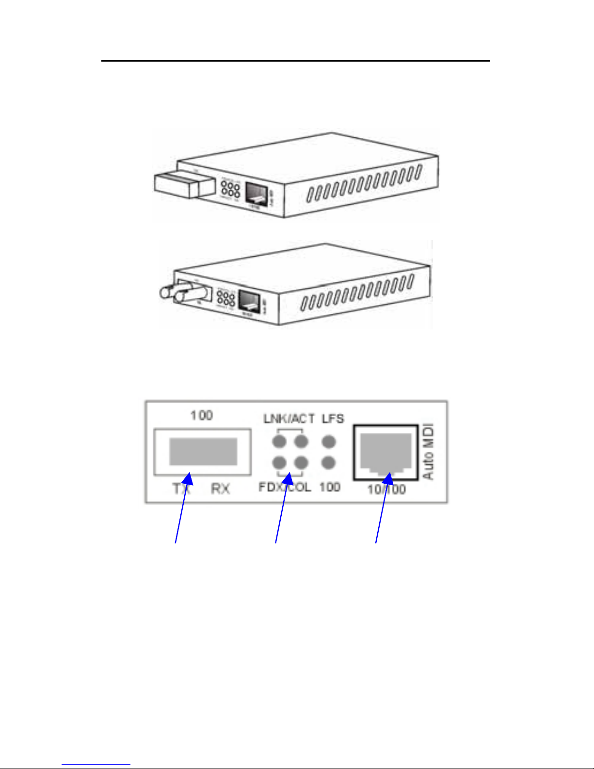
This Converter is equipped with an RJ-45 port and a
fiber optic ST or SC or WDM port. This allows it to
quickly integrate a 10/100Base-TX network into a
100Base-FX (fiber) network.
It features DIP switches for manual half or full duplex
mode configuration on both copper and fiber ports. In
full duplex mode, this Converter has the ability to
support distances of up to 2 kilometers for multi-mode
Page 10
EX-9543 Enhanced 10/100Base-TX to 100Base-FX Converter
- 6 -
fiber and up to 60 kilometers for long-haul single mode
fiber between a LAN switch, file server or another
networking device.
Converter with SC and RJ-45 Connectors
Converter with ST and RJ-45 Connectors
Front Panel View
Fiber
LED
Copper
Page 11

EX-9543 Enhanced 10/100Base-TX to 100Base-FX Converter
- 7 -
3 Installation
To install your Converter, please see the follow ing
procedures:
• Location
• Switch Settings
• NWay settings
• Link Fault Signaling
• Loopback Test
• Install the Converter
Location
The location selected to install the Converter may
greatly affect its performance. When selecting a site,
we recommend considering the following rules:
• Install the Converter in a fairly cool and dry place.
See Technical Specifications for the acceptable
temperature and humidity operating ranges.
• Install the Converter in a location free from strong
electromagnetic field generators (such as motors),
vibration, dust, and direct exposure to sunlight.
• Leave at least 10cm of space at the front and rear of
the unit for ventilation.
• Affix the provided rubber pads to the bottom of the
Converter to protect the case from scratching.
Page 12
EX-9543 Enhanced 10/100Base-TX to 100Base-FX Converter
- 8 -
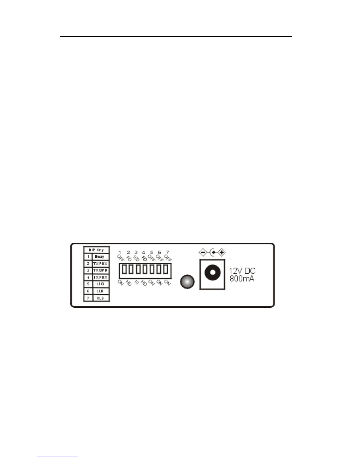
DIP Switches
DIP 1 – Enables / disables auto-negotiation (RJ-45)
DIP 2 – Copper port (RJ-45) duplex mode: full or half-
duplex
DIP 3 – Copper port (RJ-45) data bit rate: 10Mbps or
100Mbps
DIP 4 – Fiber port duplex mode: full duplex or half-
duplex
DIP 5 – Enables / disables Link Fault Signaling (LFS)
DIP 6 – Enables / disables Local Loop Back (LLB)
DIP7 – Enables / disables Remote Loop Back (RLB)
Notes: All models in this series feature the above
set of DIP switches.
Page 13

EX-9543 Enhanced 10/100Base-TX to 100Base-FX Converter
- 9 -
NWay DIP Switch Setting
Use the NWay DIP switch to activate NWay
operations.
Factory NWay DIP switch default set to ON position.
Check that the networking device to be connected to
the Converter has NWay support.
If YES: Check that the NWay DIP switch is set to the
ON position. The Converter will automatically
set the optimum speed and duplex mode on
the copper segment. Users can skip the
settings for DIP switches 2 and 3, when NWay
is activated.
If NO: Set the NWay DIP switch to the OFF position.
Then Use DIP switch 2 to manually select
between half (HD) and full duplex (FD) modes.
Use DIP swit ch 3 to manually select between
10Mbps or 100Mbps speeds. Set NWay
switch to OFF position when connecting to an
auto-sensing device that only supports
10/100Mbps detection. Some early switch
Page 14

EX-9543 Enhanced 10/100Base-TX to 100Base-FX Converter
- 10 -
models only support auto-sensing of speed,
and NOT auto detection of speed and duplex
mode (auto-negotiation).
NWay DIP Switch Setting continue
Setting the duplex mode is feasible while the
media converter is “on-line”
Note: If you experience the following problems, please
check if the NWay switch is properly set.
1. The LNK (link) LED is not lit and the
connection cannot be established
2. The LNK LED is lit and the connection is ok,
but cannot transmit or receive data
3. The converter functions properly for a while,
then, it does not work. And then it works after
powering off and then on again.
Important
In order to configure DIP switches 2 (duplex
mode) and 3 (speed), you must set DIP
switch 1 (NWay) to the OFF position
Page 15

EX-9543 Enhanced 10/100Base-TX to 100Base-FX Converter
- 11 -
Link Fault Signaling (LFS)
LFS is a “nice to have” function that is extremely
beneficial in terms of network status monitoring. The
LFS LED will immediately light to indicate when a
cable has been severed or when some other cause of
disruption in service has occurred. The LFS function
monitors both copper and fiber segments giving a total
connection status report.
Set LFS to ON position for normal operational use.
Set LFS to OFF position when installing cables or
when testing the network connection.
Note: The LFS feature influences both fiber and
copper segments. Therefore, when disruption occurs
on either segment, the LFS feature will be activated
and the LED will light to indicate that the entire
connection is down.
To appreciate the full benefits of LFS, four converters
can be used to build a primary and a secondary link.
They must be connected to a switch that supports
Spanning Tree or Fast Spanning Tree protocols. By
default, transmission of data will travel via the primary
link. Once a fault has been detected, transmission will
Page 16

EX-9543 Enhanced 10/100Base-TX to 100Base-FX Converter
- 12 -
automatically be switched to the secondary link,
resulting in ‘non-stop’ network connectivity.
Loopback Test
This Converter features DIP switches to activate both
local and remote loopback diagnostic test functions.
Use local loop back to check if the copper segment is
connected properly, and use remote loop back to
check if the fiber segment is connected properly.
Please see Diagram below:
Dip Switch 6 ON: enables local loop back function
OFF: disables local loop back function
Dip Switch 7 ON: enables remote loop back function
OFF: disables remote loop back function
Make sure that the cables are connected properly
before getting started. Conduct either the local or
remote test, not both at the same time. Follow the
steps below to perform the diagnostic tests.
Page 17
EX-9543 Enhanced 10/100Base-TX to 100Base-FX Converter
- 13 -
Local Loopback
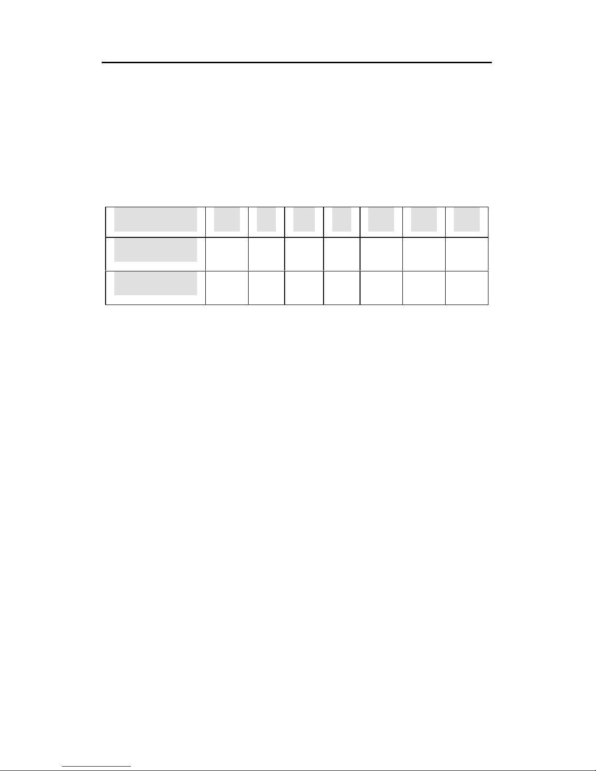
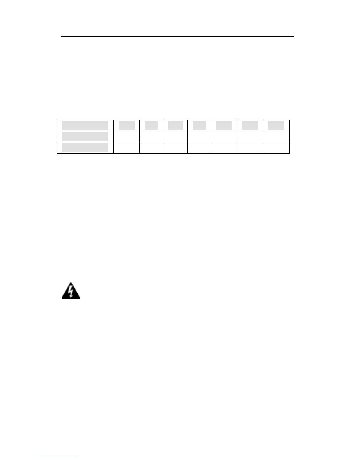
1. Test Condition setup – for the function to produce
an accurate result, be sure to set switches
according to the table below:
Test Condition
2. Launch a loopback or diagnostics testing program
and follow the instructions given. Typically, the
instructions will be similar to the following:
a. Enter the number of test messages
(frame packets) to be sent (Between 1 –
1000)
b. Click on the START button
c. The program will send a testing
message looped in the copper segment,
and display a pass/fail result
DIP Switches 1 2 3 4 5 6 7
Converter A OFF FD 100 FD OFF ON OFF
Converter B OFF FD 100 FD OFF OFF OFF
Page 18
EX-9543 Enhanced 10/100Base-TX to 100Base-FX Converter
- 14 -
Remote Loopback
1. Test Condition setup – In order for the function to
produce an accurate result, set switches
according to the table below:
Test Condition
2. Launch a loopback or diagnostics testing program
and follow the instructions given. Typically, the
instructions will be similar to the following:
a. Enter the number of test messages
(frame packets) to be sent (Between 1 –
1000)
b. Click on the START button
c. The program will send a testing
message looped in the fiber segment,
and display a pass/fail result
NOTE: On a PC, use a program such as Sniffer to conduct the tests.
Other methods include the use of SmartBits series testing
equipment. If you do not have access to either method,
please contact your vendor for advice.
DIP Switches 1 2 3 4 5 6 7
Converter A OFF FD 100 FD OFF OFF OFF
Converter B OFF FD 100 FD OFF OFF ON
Warning Be sure to deactivate both local and remote
both loopback test functions for normal converter operations
Page 19

EX-9543 Enhanced 10/100Base-TX to 100Base-FX Converter
- 15 -
Install the converter
This Converter utilizes ports with fiber and copper port
connectors functioning under Ethernet and/or Fast
Ethernet protocols.
10/100BASE-TX Port
The 10/100BASE-TX port supports network speeds of
either 10Mbps or 100Mbps, and can operate in half-
and full duplex transfer modes. This port also offers
automatic MDI/MDI-X crossover detection that gives
true "plug and play" capability - just plug-in the
network cable to the port and the port will adjust
according to end node device automatically. The RJ-
45 connector is suitable for UTP cable Category 3, 4,
5 or better.
100BASE-FX Port
The 100BASE-FX port adds a fiber Fast Ethernet link
to your network device. Compliant with IEEE 802.3u,
this port can transmits data at 100Mbps in full duplex
mode across distances of up to 2km over multi-mode
fiber-optic cable. The fiber port has a choice of three
fiber connector types: ST, SC and WDM.
Page 20

EX-9543 Enhanced 10/100Base-TX to 100Base-FX Converter
- 16 -
Desktop Installation
Follow the instructions listed below to install the
Converter onto a desktop location.
1. Locate the Converter in a clean, flat and safe
position that has easy access to AC power.
2. Affix the four (4) self-adhesive rubber pads to the
underside of the Converter.
3. Apply AC power to the Converter. (The green PWR
LED on the front panel should light).
4. Connect cables from the network partner devices
to the ports on the front panel. (The green LNK
LED on the front panel associated with the port
should light).
This Converter can also be mounted on a vertical
surface. Simply use the underside of the unit as a
template to measure and mark out the position of the
holes on to the surface where the unit is to be installed.
Then use two screws to mount the converter firmly in
place.
Page 21

EX-9543 Enhanced 10/100Base-TX to 100Base-FX Converter
- 17 -
Getting Connected
Powering On Unit
The Converter uses an AC power supply 100~240V
AC, 50~60 Hz. The Converter's power supply
automatically self-adjusts to the local power source
and may be powered on without having any or all LAN
segment cables connected.
1. Insert the power cable plug directly into the
receptacle located at the back of the device.
2. Plug the power adapter into an available socket.
Note: For International use, you may need to change the AC
power adapter cord. You must use a power cord set that
has been approved for the receptacle type and electrical
current in your country.
Warning
Please exercise caution when using power tools. Also,
install this unit away from damp or wet locations, or i n
close proximity to very hot surfaces. These types of
environments can have a detrimental effect on the
converter and cables. An ideal location is a lightly
cooled place such as a typical equipment room.
Because invisible laser radiation may be e mitted from
the aperture of the port when no cable is connected,
avoid exposure to laser radiation a nd do not stare int o
open apertures.
Page 22

EX-9543 Enhanced 10/100Base-TX to 100Base-FX Converter
- 18 -
2. Check the power LED on the rear of the Converter
3. when the device is powered on to verify that
power is applied. If not, check that the power
cable is correctly and securely plugged in.
4.
Connecting Fiber Cable
When connecting fiber cable to a 100BASE-FX port
on the Converter, be sure the correct type - ST or SC
or WDM - connector is used. Follow the steps below
to properly connect fiber cable:
1. Remove and keep the ST/SC/WDM port's rubber
cover. When not connected to a fiber cable, the
rubber cover should be replaced to protect the
optics.
2. Check that the fiber terminators are clean. You
can clean the cable plugs by wiping them gently
with a clean tissue or cotton ball moistened with a
little ethanol. Dirty fiber terminators on fiber optic
cables will impair the quality of the light
transmitted through the cable and lead to
degraded performance on the port.
3. Connect one end of the cable to the ST/SC/WDM
Page 23

EX-9543 Enhanced 10/100Base-TX to 100Base-FX Converter
- 19 -
port on the Converter and the other end to the
ST/SC/WDM port on the other device.
Note: When inserting the cable, be sure the ta b on the plug
clicks into position to ensure that it is properly seated.
5. Use DIP switch 4 to select between half and full
duplex modes for the fiber port
6. Check the corresponding port LED on the
Converter to make sure that the connection is
valid. (Refer to the LED chart in next section)
Connecting Copper Cable
The 10/100BASE-TX RJ-45 Ethernet port fully
supports auto-sensing and auto-negotiation.
1. Insert one end of a Category 3/4/5/5e type twisted
pair cable into an available RJ-45 port on the
Converter and the other end into the port of the
network node.
2. Check the corresponding port LED on the
Converter to be sure that the connection is valid.
(Refer to LED chart in next section)
Page 24

EX-9543 Enhanced 10/100Base-TX to 100Base-FX Converter
- 20 -
4 LED Indicators
This Converter has LED indicators located at the front
of the device. The LEDs have been designed to give
easy at-a-glance network status, and provides ‘real-
time’ connectivity information. Please see below for an
interpretation of their functions:
Unit LEDs
LED Condition Status
On (Green)
Converter is
receiving power
PWR
Off
Power off or
failure
On (Red)
Disruption of
connection in
copper/fiber
segment
LFS
Off
Copper/fiber
segment is ‘OK’
Page 25

EX-9543 Enhanced 10/100Base-TX to 100Base-FX Converter
- 21 -
Port LEDs
LED Condition Status
On (Green)
Port operating at
100Mbps
100
Off
Port operating
below 100Mbps
On (Green)
Illuminated when
connectors are
attached
Flashing (Green)
Data traffic
passing through
port
LNK/ACT
Off
No valid link
established on
port
On (Amber)
Port is operating
at full duplex
Flashing (Amber) Indicates collision
FDX/COL
Off
Port is operating
at half-duplex
Page 26
EX-9543 Enhanced 10/100Base-TX to 100Base-FX Converter
- 22 -
Appendix A
Cables
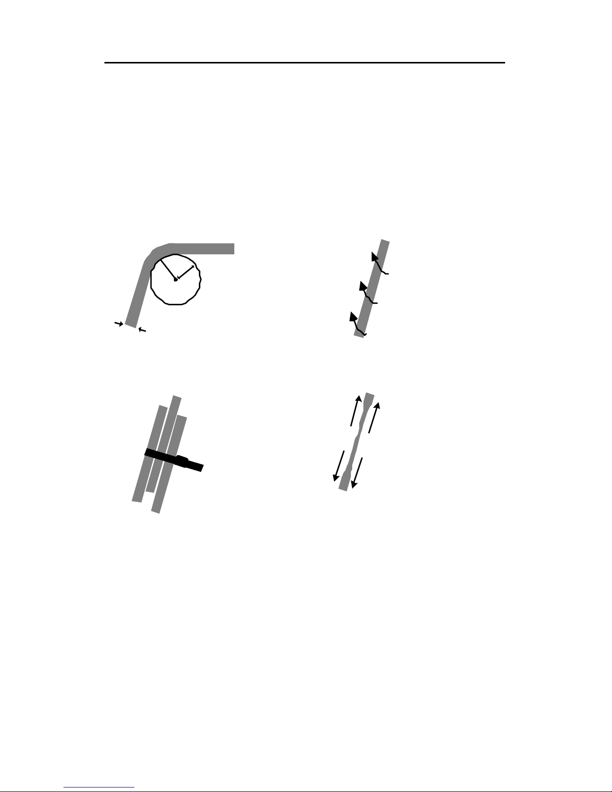
The following are some recommendations as to what
you should and should not do when installing cables.
Remember - cables are the deciding factor in network
performs
2
4
m
m
6
m
m
Tr y to
maintain
a bend
radius of
(m in.) 4x
the diameter
of the cable
for UTP and
100x for fiber.
Try not to
allow the
cable to
t wis t to o
much - this
creates a
strain on
the internal
cables.
Place cable ties
at regular
intervals - do
not over tighten
cable ties - try
to avoid usi ng
with fiber.
Do not stretch
the cab le
especially on
corners, in
vertical cable
t rays a nd when
spanning long
d istances.
Page 27
EX-9543 Enhanced 10/100Base-TX to 100Base-FX Converter
- 23 -
Appendix B
About RJ-45 Cables
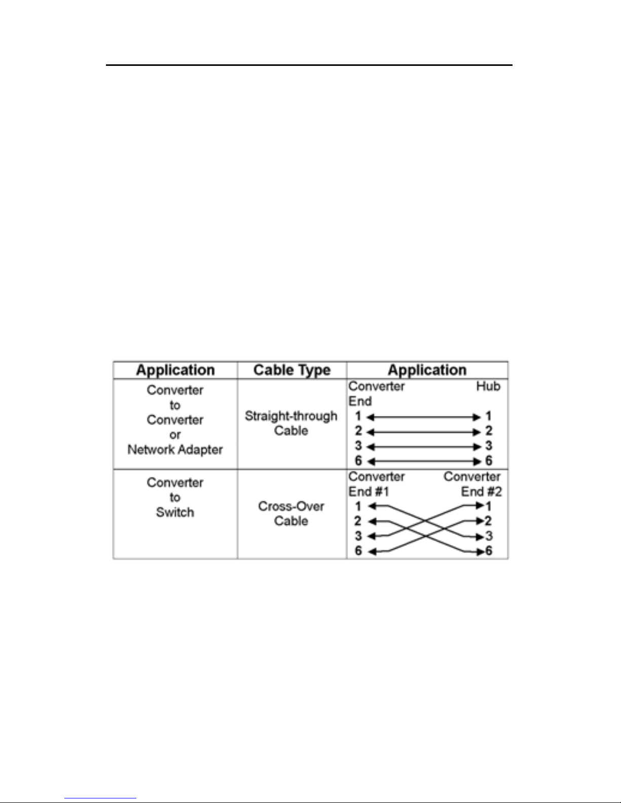
When connecting your network devices, use standard
Category 3 eight-way cables for 10Base-T
configurations and Category 5 cable for 100Base-TX.
The pin assignments are as follows:
Pin 1 TD+ Pair 2 White/Orange
Pin 2 TD- Pair 2 Orange/White
Pin 3 RX+ Pair 3 White/Green
Pin 4 N/A Pair 1 Blue/White
Pin 5 N/A Pair 1 White/Blue
Pin 6 RX- Pair 3 Green/White
Pin 7 N/A Pair 4 Brown/White
Pin 8 N/A Pair 4 Brown/White
Note: Automatic MDI/MDI-X selection on RJ-45 port
Page 28

EX-9543 Enhanced 10/100Base-TX to 100Base-FX Converter
- 24 -
Appendix C
Mini Converter Chassis
The Chassis is developed to accommodate just one
media converter. The Chassis provides AC or DC
power protection for converter units. Now, network
designers can plan their Ethernet, Fast Ethernet, ATM,
or Gigabit networks without having to worry about the
power source. Furthermore, its unique sizes allows it
to be installed in locations where space is limited.
Features
• Simple and easy to install
• Adds fiber connectivity to otherwise copper based
networks
• Supports 10/100/1000Base, copper, fiber,
single/multi-mode, ST, SC, MT-RJ, VF-45, LC,
WDM connector converters
• Supports one media converter
• Suitable for all size of networks in all locations
• Provides internal AC and DC switching power
supply
• Made from high quality durable steel
• Optional external redundant power adapter
Affixing Brackets
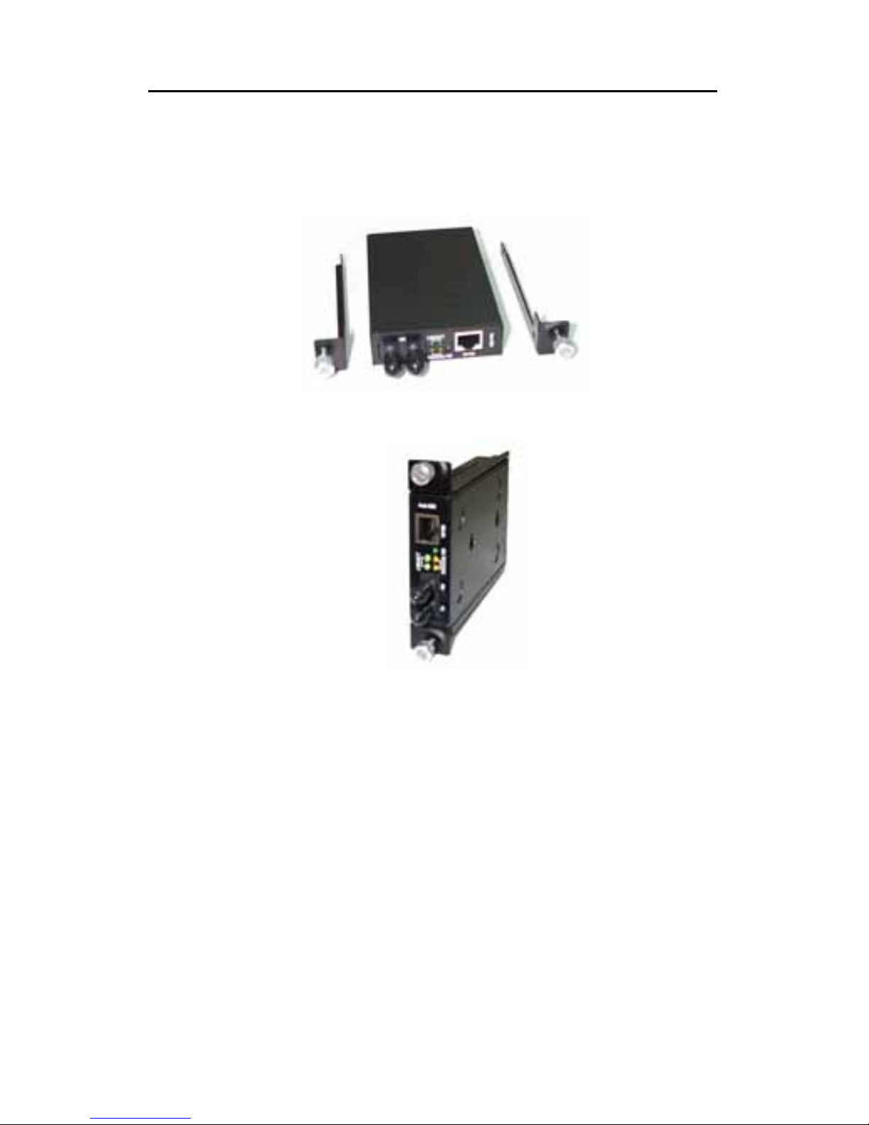
We have supplied 2 special brackets that easily
attaches to the Converter. This allows for the secure
placement of the Converter into the Chassis. It also
Page 29
EX-9543 Enhanced 10/100Base-TX to 100Base-FX Converter
- 25 -
seals off the front of Chassis and allows it to function
correctly.
Step 1 Using a Phillips screwdriver, remove two screws from
the side panels on the converter.
Step 2 Place the converter and brackets on a flat horizontal
surface as illustrated above. Secure the brackets by
replacing the screws.
Ensure that the rails are flush-mounted with the underside of
the Converter. The Converter is now ready for loading into the
Chassis.
Page 30
EX-9543 Enhanced 10/100Base-TX to 100Base-FX Converter
- 26 -
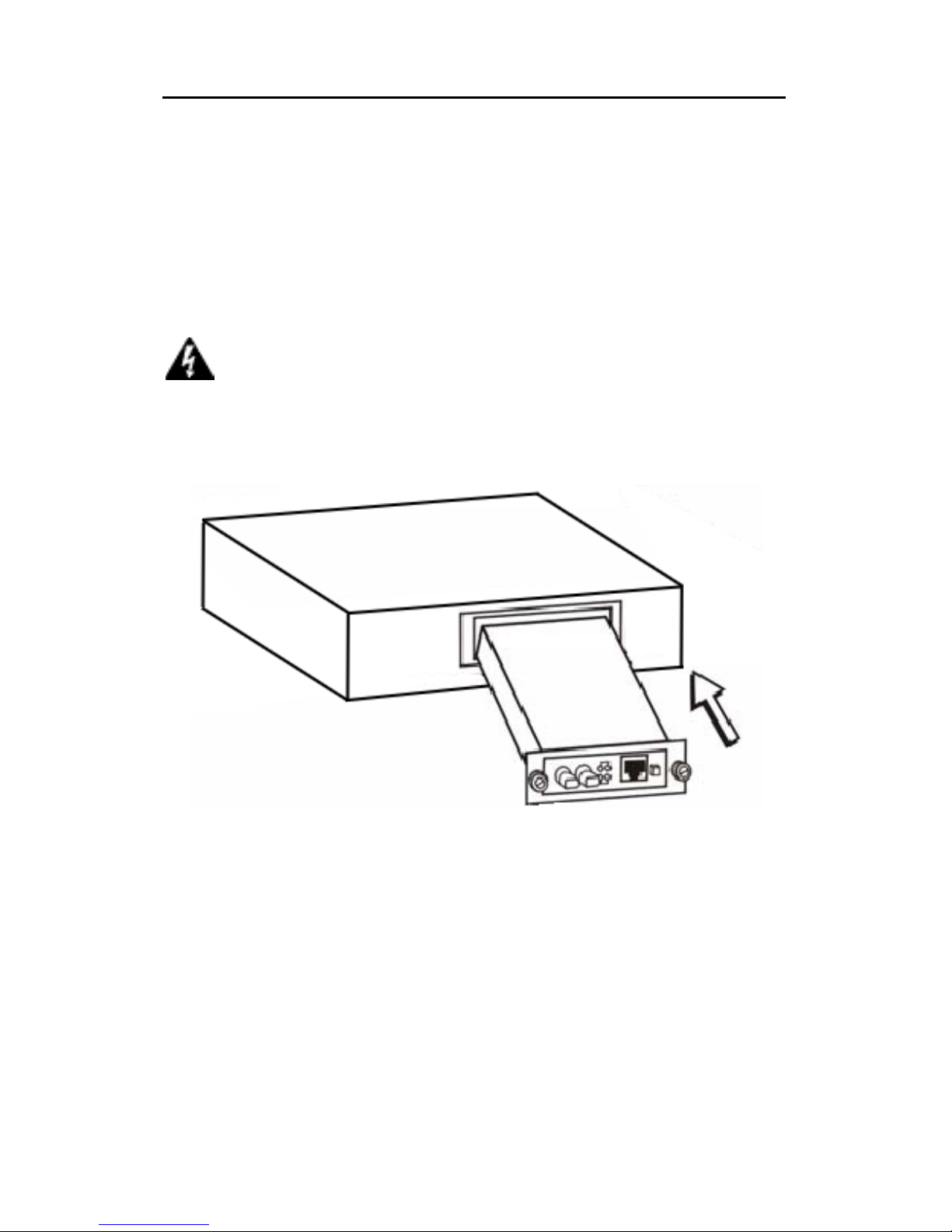
Installing the Converter
Once the Converter has been attached to the bracket,
it can be installed into the Chassis. Special care must
be taken to ensure the correct mating of the power
connector. Align the Converter so that it fits between
the upper and lower guide rails.
Warning
A
lways ensure that the converter
power socket is positioned at the base of the
Chassis. Never force the Converter into the
Chassis - check power socket position and
alignment.
Page 31
EX-9543 Enhanced 10/100Base-TX to 100Base-FX Converter
- 27 -
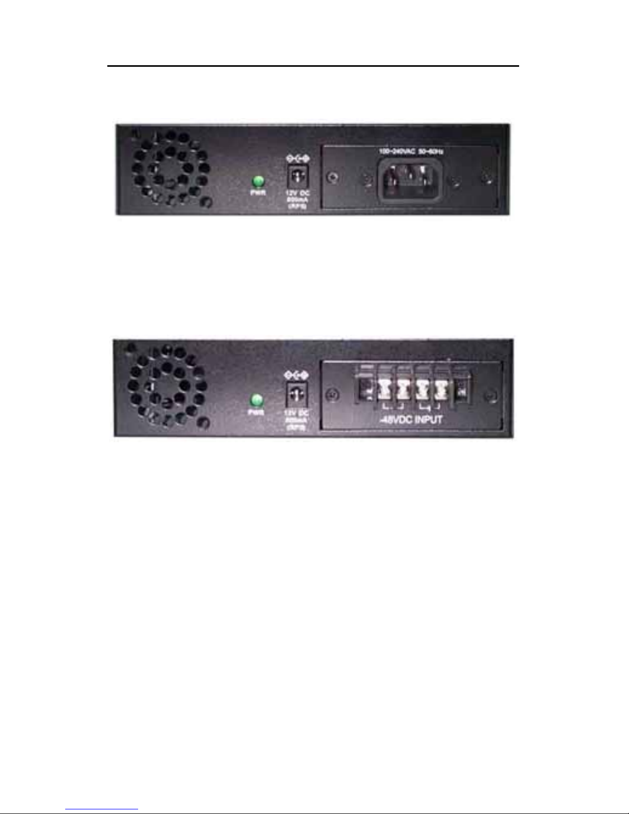
Rear view of Chassis and specifications
Rear View of Chassis with AC Power Supply
Power: 100 - 240V AC (Optional 12V Adapter)
Dimensions: 109 x 174 x 44.3 mm (L x W x H)
Rear View of Chassis with DC Power Supply
Power: -48V DC (Optional 12V Adapter)
Dimensions: 109 x 174 x 44.3 mm (L x W x H)
Page 32
EX-9543 Enhanced 10/100Base-TX to 100Base-FX Converter
- 28 -
Appendix D
Application Diagrams
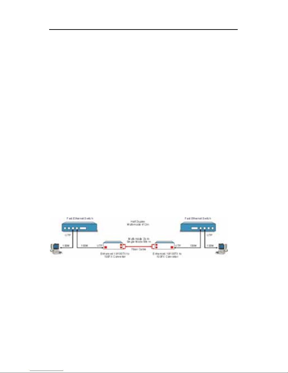
To effectively expanding a Fast Ethernet network,
position two converters back-to-back as illustrated.
Application Diagram I
In the figure below, the Converter is functioning as a
high-speed bridge between switches creating
increased capacity for each user (node) on the local
area network. It is providing a 100Mbps full duplex link
to a variety of Fast Ethernet network devices within a
LAN.
Switch ↔ CONVERTER ↔ CONVERTER ↔ Switch
Page 33
EX-9543 Enhanced 10/100Base-TX to 100Base-FX Converter
- 29 -
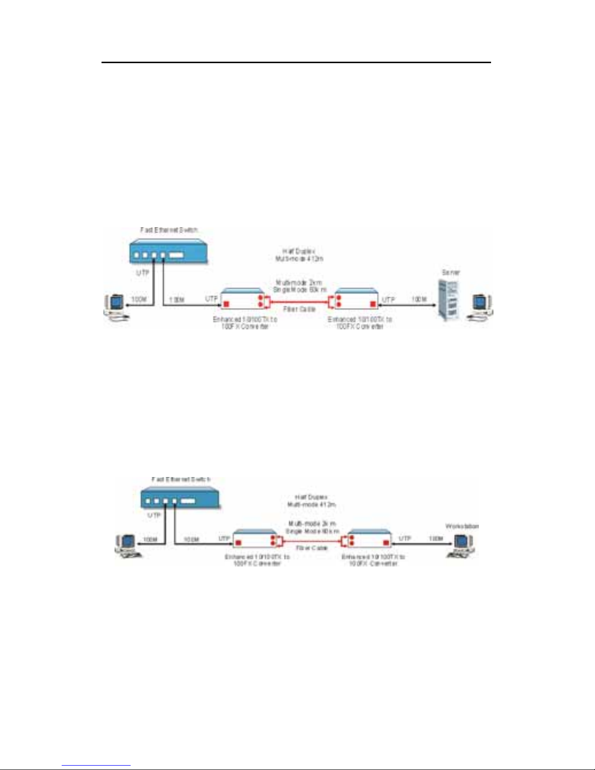
Application Diagram II
In the figure below, the Converter is functioning as a
server aggregation for an enterprise or LAN
configuration. It is providing a 100Mbps full duplex link
to a workgroups of 10/100 switches located on
separate floors within a single building.
Switch ↔ CONVERTER ↔ CONVERTER ↔ Server
Application Diagram III
In the figure below, the Converter is functioning as a
high-speed dedicated link within a campus network
configuration. It is providing a 100Mbps full duplex link
to a remote network node.
Switch ↔ CONVERTER ↔ CONVERTER ↔ Switch
 Loading...