

Experimental Aircraft Models Velocity XL Assembly Instructions Manual

Scale: 1= 4.65
Wingspan: 80” (2032 mm)
Wing Area: 1103 in2 (7117 dm2)
Flying Weight: 14 -15 lbs (6.4 – 8.8 kg)
Wing Loading: 31 oz/ft2
Length: 50 ¾” (1290 mm)
Radio: 4 Channels with 8 servos
Engines: 1.20 Two Cycle, w/Fuel pump
Experimental Aircraft Models, LLC (EAM) guarantees this kit to be free from defects in material and
workmanship. The warranty does not cover individual parts damaged by modification or abuse. In no case will
EAM’s responsibility or liability exceed the original purchase price of the kit. EAM reserves the right to change
EAM assumes or accepts no liability for the manner in which this model aircraft is used by the user, in any
condition of assembly. By the act of purchasing this kit, the purchaser and any subsequent user accepts full
If the purchaser is not willing to accept the above liability associated with the use of this model aircraft,
the purchaser is advised to return this kit immediately to the source from where it was obtained.
Please read this manual thoroughly before starting assembly. It includes critical
assembly instructions and warnings in regards to the safe and enjoyable use of
Kit Contents
this scale aircraft model.
Velocity XL
Radio Control Scale Model
Assembly Instructions
or modify this warranty at any time.
responsibility and all resulting liability.
“Enhancing the Homebuilt Experience”
Warranty
Experimental Aircraft Models, LLC
32009 Lee Lane
Farmington, MI 48336
Experimental Aircraft Models
Entire Document © Copyright 2005
- 1 - WWW.RCHomebuilts.com

About Your Model :
Velocity XL RC model kits in the world. You have a very unique model of an
Experimental aircraft.
In the United States, ‘Experimental Aircraft’ are aircraft that are 51% or more built by an individual (usually at
home) and are licensed by the FAA under a special “Experimental” certificate, rather than “Certification”. The
purpose of the Experimental category is to allow private individuals to design and build, and market, their own
aircraft typically for the purpose of education. During the past 20 years the most advanced designs in civil
aviation aircraft have come from the ‘Homebuilt’ arena where, without the burden of certification expense and
manufacturers liability insurance, aircraft of amazing performance and safety could be designed and offered to
the public. The Velocity XL clearly stands out as a supreme example that type of ingenuity.
In our mission to support the homebuilder with a scale model of an aircraft project that may have consumed
hundreds/thousands of hours to complete, we have brought together full-scale aircraft kit airframe
manufacturers with a state-of-the-art world class ARF (Almost Ready to Fly) model manufacturer. Our intent is
to provide as scale a model as possible that is as ARF as possible - within the confines of limited size
production runs, and the knowledge that a full scale builder will likely customize to match their own aircraft. In
that sense, this product caters more to the full scale builders, and scale modelers, than it does ‘out of the box’
flyers. (Translated: There is enough to do to finish the model that you’ll feel a sense of pride in ownership!)
Specifically with our Velocity there is a small amount of epoxy/glass tape work (supplied), soldering of the
nose gear with a propane torch and masking and painting of the canopy and fuselage.
Just as the homebuilder customizes their personal aircraft, we have offered the model in pure white, so that
you may do the same.
For those unfamiliar with the Velocity XL design, the original version came (and still does) with a fixed tricycle
landing gear. The retractable gear version was developed a few years later by a customer, who later
purchased the company(Duane Swing). We have elected to offer the kit in the fixed tri-gear version, simply
because it would allow us to focus our development efforts on a good flying model and allow us to bring the
model to market in a reasonable amount of time. (Even then it wasn’t reasonable!)
Please note that we use aircraft terminology in our instructions. Specifically ‘Port’ is left and ‘Starboard’ is
Right, and ‘Forward’ is to the front and Aft is to the rear. No matter how you may have the model turned, Port
is always the left side of the aircraft as the pilot sits in the cockpit facing forward. Thus if you are working on
the model upside down with the tail facing towards you while installing servos, putting something on the Port
side eliminates the confusion that ‘left’ side might result in.
A final point: Because the model is so special and the volumes (by model standards) so low, we need your
help. We have tried our absolute best to get everything right the first time. If there is something during the
construction and flying of the model that you feel could be done more easily or better, we’d like to know. This
is how it’s done in the full size experimental aircraft world, and we want to be sure that the same spirit is
carried on in smaller scale. Builders are continually finding ways to improve the full size aircraft, and there is
no reason why modelers should not have the same ability to contribute to a better product.
Please feel free to e-mail us with kit comments at: info@RCHomebuilts.com
vote of confidence in purchasing our rendition of Velocity Aircraft’s Velocity XL, and truly wish you the best of
enjoyment.
Cleve L. Lee
Managing Director
Experimental Aircraft Models, LLC
You have purchased one of a limited production run of
We sincerely appreciate your
Experimental Aircraft Models
- 2 - WWW.RCHomebuilts.com
A note about the covering. Your Velocity XL’s wings, canard and winglets are covered in White
‘Oracover’ – commonly known as ‘Ultracote’ in the U.S. This is a high quality material, but through
temperature changes during shipping, the model may show wrinkles. This is normal. This symptom
is also more visible in that the model is fully balsa sheeted. The material can easily be tightened by
the application of heat from a hair dryer/heat gun or hot iron. If using an iron, a piece of lightweight
cotton (e.g. sheeting) placed between the iron and the covering helps to even the heating. Pressing
lightly will transfer the heat to the covering, shrinking the material. Piercing a bubble with a pin and
rubbing the hot area with a cloth further helps remove the wrinkles.
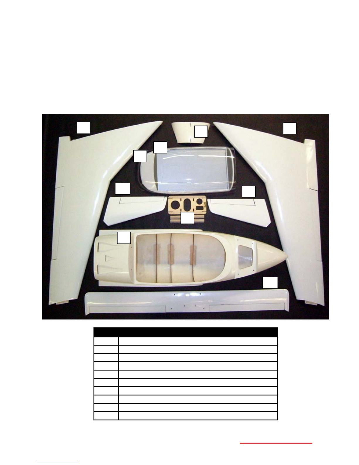
Airframe Components
A
G
D
C
B
F
H
I
J
E
Item Description
A Starboard (Right) Wing
B Canopy
C Cockpit Cover
D Canard Cover
E Port (Left) Wing
F Port Winglet
G Starboard Winglet
H Fuel Tank Ply Platform
I Fuselage
J Canard
Experimental Aircraft Models
- 3 - WWW.RCHomebuilts.com

Hardware
9
10
1
2
3
4 5
6 7
8
Item
20
22
23 24 25
26
21
43
18
16
40
15
14
13
39
19
27 28 30 31 32 29
42 41
17
Description Where Used Qty.
11
12
33 34
38 37
36
No.
1 Fiberglass Cowling Cowling 1
2 2.3 x 6 mm washer head screw Cowling attach screws & Misc. 22
3 Spinner 76mm Dia Engine 1
4 Glass filled Nylon Engine Mount Firewall 1
5 4 x 25mm Pan Hd Phillips Bolt, 4 mm Blind
Engine mount attachment 4 ea.
Nut, 4 mm Flat Washer
6 Clear PVC molded boxes Carve to make 3 Air Ducts 3
7 ¼-20 x 2” Nylon Finger Bolts Wing Retaining Screws
8 White PVC cowling scoop Side of Cowling 1
9 Formed & Polished Main Landing Gear Main Landing gear 1
10 8-32 x 1” socket head screw, washers &
Main landing gear attachment 4
Locknuts
11 Wheel Pant Set (2) Mains (1) Nose gear 1set
12 3 x 12 mm Phillips screw Wheel Pant Retaining 2
13 4 mm I.D. x 3” (76mm) O.D. Main Wheels 2
14 4 mm I.D.x 2 3/8” (60mm) OD Nose Wheel 1
15 4 mm ID collars Main Wheel Retaining 2
16 4 mm ID Nylon spacers Nose Wheel Spacing 2
17 4 mm Axle Set Main Landing Gear Axles 2
18 1.8mm x 500 mm wire Throttle Pushrod Wire 1
19 EZ Connector Throttle & Steering Servos 2
35
Experimental Aircraft Models
- 4 - WWW.RCHomebuilts.com

Item
Description Where Used Qty.
No.
20 25 mm O.D x 792 mm Al Tube Support Wings Thru Fuslg. 1
21 Double Strut Wire Nose Gear Nose Gear 1
22 Nylon Strap Secure Nose Wheel Fairing 2
23 2.3 x 8mm Phillips head screw Secure Nose Wheel Fairing 4
24 Nylon Steering Housing & Control Arm Nose Gear Pivoting 1
25 4-40 x ¾”” Socket Head Bolt Secure Nose Gear Housing 4
26 1.8 x 130 mm Nose Wheel Pushrod Nose wheel steering 1
27 4 – 40 x 1” Socket Hd. Bolt & Washers Canard & Canopy mount 6
28 Nylon Rod Pivot Ends Rudder & Elevator arms 4
29 1.8 x 55 mm Pushrods (threaded one end) Elevator Pushrods 2
30 Clevis Ailerons & Elevators 4
31 Nylon Kwik Keepers Ailerons & Elevators 4
32 Nylon Latch Covers & Aileron Hinges Canard Cover 6
33 Control Horns Ailerons 2
34 2.3 x 20 mm Machine Screws Control Horn Attachment 4
35 1.8 x 95 mm Pushrods (Threaded one end) Aileron Pushrods 2
36 2.3 x 12mm Washer Hd. Screw Winglet Attachment 8
37 8 x 12 x 16mm Blocks Servo Mounting Blocks 8
38 1.8 mm Servo Saver Assembly Rudder Operation 2 set
39 450 CC poly fuel tank Fuel Tank 1
40 Silicon rings Clevis Keepers 8
41 2 mm Allen Key Tighten various set screws 1
42 8-32 Locknuts & Washers Landing Gear Attachment 4
43 Nylon Tie-wraps Secure Fuel Tank 3
Items needed to Complete Your Velocity Model
Your Velocity model flies with a four-channel radio. However, do to the relatively ‘remote’ location of
the rudders, one servo is needed to operate each of the port & starboard rudders, and one to
operate the steerable nose gear. In addition the elevators attached to the trailing edge of the canard
utilize one servo for each elevator. This design uses smaller servos laid flat, and allows the bottom
balsa skin of the canard to remain without cutouts and improves the strength of the canard. (Along
with the hardwood spars.)
List of recommend servos or equivalent:
• (2) HS-85MG 42oz metal gear, ball bearing - Elevators
• (2) HS-85 42oz, nylon gear, ball bearing – Rudders HS-81 also acceptable
• (2) HS-425BB, Nylon gear, ball bearing – Steering & Throttle
• (2) HS-475HB, Karbonite gear, ball bearing – Ailerons
Servo Wire Extensions:
• (2) 36” – Rudder servos
• (2) 18” – Aileron servos
• (1) 6” – Throttle servo
• (2) 12” – Steering and Elevator servos
• (4) ‘Y’ connectors – (2) for Rudders/Steering, (1) Ailerons, (1) Elevators
(Hitec product numbers are shown.)
Experimental Aircraft Models
- 5 - WWW.RCHomebuilts.com
Engine, Prop and Muffler
The model has flown successfully on an OS .91FX running a two blade 14x6 APC pusher prop. This
proved that the model flies well ‘on the wing’ and is as efficient as the full-scale aircraft. It is not
adequate for any aerobatics or short runways. It is not our recommended set-up.
We recommend the Webra Speed 1.20 two cycle engine with the integral fuel pump. The Webra is
a tried and true ‘bullet-proof’ engine and powers the model with authority. Turning an Airmaster 3
blade 14x6 pusher prop the model accelerates quickly on grass and is capable of basic aerobatics.
We recommend a fuel pump because the fuel tank sits approximately 20” forward of the engine and
changes in aircraft attitude affect mixture.
Do not assume that more power is better, we already did that for you with the 1.20 size engine
recommendation. The engine sits well aft of the CG, and any changes in weight of engine are
further paid-for by increases in ballast in the nose.
Note that as a ‘pusher’ the exhaust of a ‘normal’ Pitts style muffler points in the wrong direction. We
have custom Bisson mufflers for the Webra engine, which we include in our ‘Firewall Aft Kit” and
which are available separately.
Other Stuff:
CA Adhesive (Thin)
CA Adhesive (Medium)
30 Minute Epoxy (4 oz. min.)
5 Minute Epoxy
Propane Torch
Solder & Flux
Foam Servo Mounting Tape
Rubbing Alcohol
Building the Wings
Installing Aileron Hinges
The control surfaces on the wings, canard and winglets are not yet permanently attached. In this
step you will be positioning the ailerons, remove and prepare them for gluing, and permanently
re-installing them on the wings.
Note: At the tip of the wing the plywood winglet mounting plate is shipped already taped in
position. Leave this in place because you’ll need it there later.
1) Retrieve the hinges (No. 32) from the hardware pack and the right wing.
2) Insert a pin through the middle of the hinges and
insert them half way into the pre-cut slits in the wing.
Slide the ailerons into place.
Position the hinges side to side so all hinges
fit & the space between the aileron ends and
the wings is equal – use a razor knife if
necessary to widen or deepen the slot if
necessary.
Check that the vertical location of the
factory cut slot allows the two ends of the
aileron to sit flush with the top surface of
the wing. Cut a new slot if it does not meet
your building standards.
Experimental Aircraft Models
- 6 - WWW.RCHomebuilts.com
3) Mark the location of the hinges on both the wing and control surfaces so you’ll know where
they were after you pull the aileron away from the wing. (A felt tip pen works well to make a
dot, and cleans up with alcohol.)
4) Trim away the Oracover from around the hinge
slots on both the wings and the control surfaces.
Our favorite method is to use an old soldering iron
with a point on the end. This seals the Oracover
to the wood at the same time as it melts back the
covering from the slot. Otherwise a razor knife
can be used to trim away the material. The
objective is to be sure the adhesive can wick into
the slot. You don’t want an edge of film sitting
against the hinge, which may prevent the
adhesive from flowing into the slot.
5) Drill a small (1/16” or 1.5mm) hole in the center of each slot which will help ‘wick’ the
adhesive onto the hinge in step 7.
6) Re-insert the CA hinges halfway into the slots in the aileron. (Up to the pin.)
7) Position the aileron up to the wing, inserting the other half of the hinge into the slots in the
wing. Check side-to-side alignment so that the spaces between the wing and the aileron are
equal. Remove the pins, and place 6 drops of Thin CA into the slot on both the wing and
aileron for each hinge, on both top and bottom side of the wing. Wedge a paper towel into
the opposite side of the hinge to prevent any excess CA from running down over the wing.
Check for free movement.
8) Repeat steps 1 – 7 to secure the aileron on the opposite wing.
9) Pull on the control surfaces to test their strength.
Assembling the Winglets
We’re switching to the winglets, rather than finishing up the servo installation for the ailerons,
because the rudder servo wires run through the aileron servo bay, and it’s easier to feed the wires
through when the aileron servo is not yet installed. Aileron servo installation follows this section.
The winglets provide yaw stability for the aircraft. By design each rudder operates independently of
the other, and each only moves ‘outboard’. You will see that the rudder arm inside the winglet
‘bottoms-out’ inside the winglet, preventing the rudder from moving inboard. Similarly, the rudder
hinge line is designed for this type of action. The full scale aircraft uses a
spring loaded rudder against a stop, and uses a cable to pull on the control
arm. Rather than use complicated cables (for a model), you will be installing a
servo on the bottom plate of each winglet. We will allow the servo to operate in
both directions so as to not require separate channels to operate the rudder
servos,. To allow this, you will be installing a ‘servo saver’ type of mechanism
(#38) that pulls the rudder in one direction, and pushes against a spring in the
other. This simple design also allows for easy removal of the winglet from the
wing by removing the four securing screws and unplugging the servo.
1) Retrieve the starboard (right) winglet.
Experimental Aircraft Models
- 7 - WWW.RCHomebuilts.com
2) Mark the locations of the hinges. Pull the rudder away from the winglet and prepare hinge
slots for bonding as you did with the ailerons.
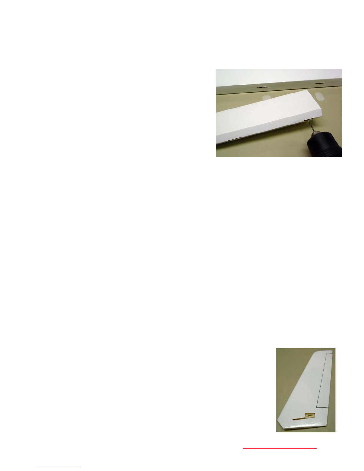
3) While the rudder is removed, retrieve a Nylon Rod
Pivot End (#28), open the hole through the barrel to
5/64” and thread onto the arm until flush with the end.
4) Retrieve the Rudder Servo Savers (#38) and the 2
mm Allen key (#41)
5) Snug the setscrew on the collar farthest from the Z
bend so the assembly does not fall apart when handling it, and test fit the ‘Z’ bend end of the
Servo Saver pushrod into the Rod Pivot End, inserting from the top side of the Pivot Rod
End, and check for smoothness of
operation with the pushrod
perpendicular to the winglet. You
may have to rotate the Rod Pivot
End slightly downward and/or adjust
the ‘Z’ bend. When done, remove
the pushrod from the Rod Pivot End to
simplify the next step.
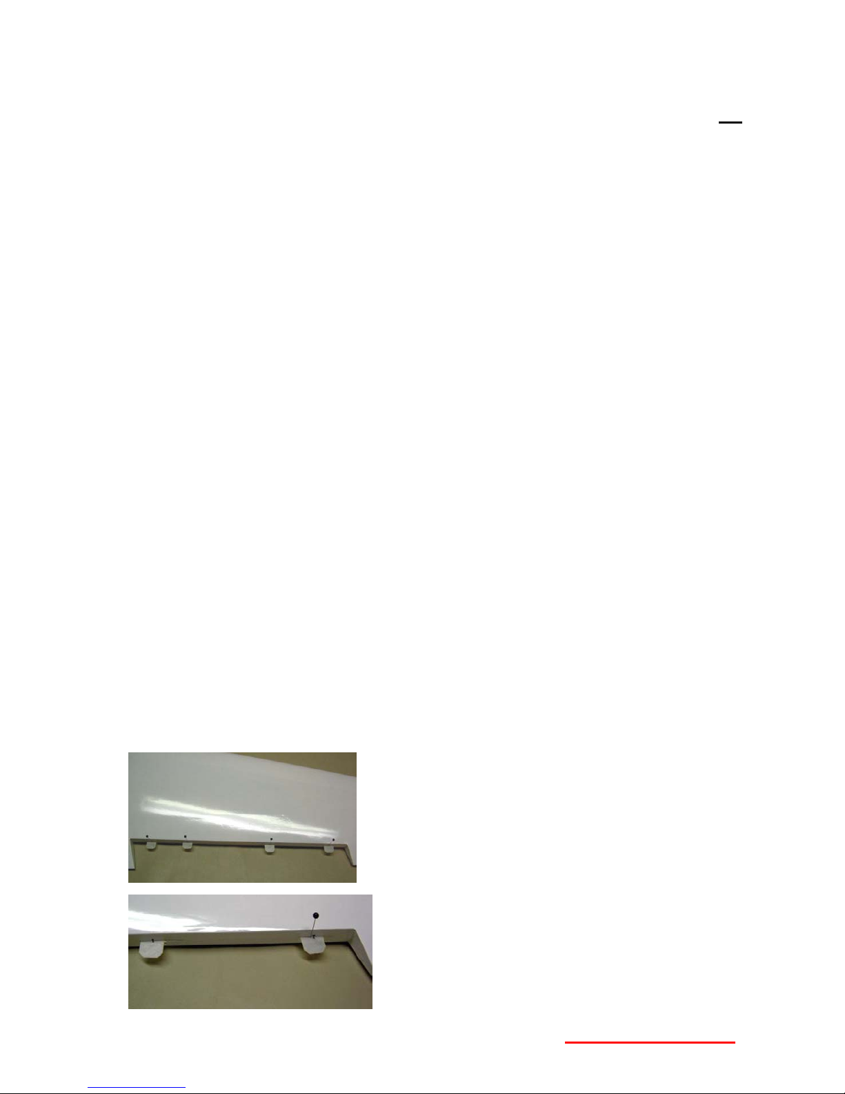
6) Retrieve the starboard wing with the ply winglet attach plate still in place. (Tape it back in
place if you removed it!) Read the next few steps below to familiarize yourself with the
activity and objective before starting.
Slide the winglet over the protruding end of the plate until it
is against the wing tip. This ensures that the back edge of
the plate is fully seated in the recess, and that the plate is
inserted to the proper point in the winglet.
On the bottom of the wing, use
a razor knife and score/cut the
covering on the bottom of the
plate, at the surface of the
winglet.
Remove the winglet/plate from
the wing, separate the plate from the winglet and remove the
covering on the end of the plate.
30 Minute epoxy the plate into the winglet, using the wing again as
a ‘positioning fixture’. Place the glue into the slot in the winglet and on the end edge of the plate.
Remove from the wing (so it doesn’t bond to it!) Clean up any excess epoxy on the winglet and
wing with alcohol or vinegar and set aside to dry.
7) Repeat steps 1-6 above to complete the winglet/plate assembly for the port wing.
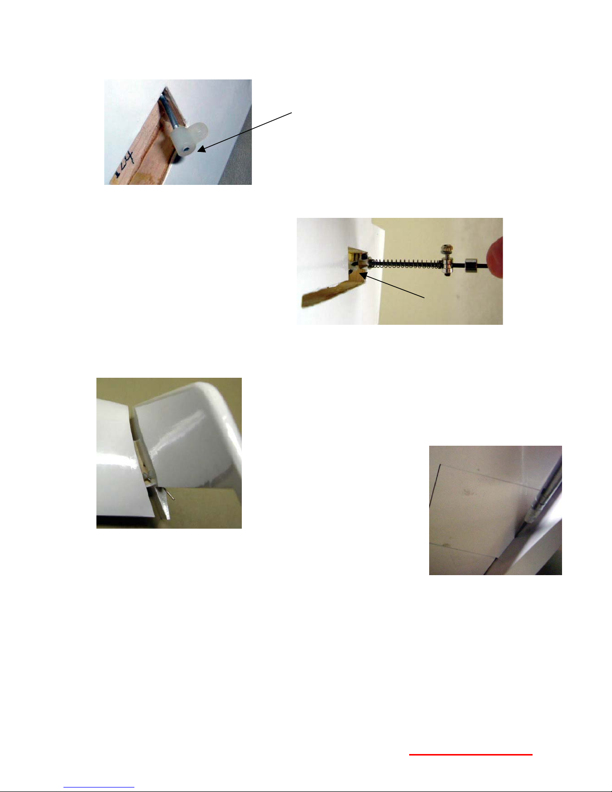
8) Assuming the starboard winglet/plate assembly is now dry;
a. Test fit the rudder on the CA hinges. Check that when the rudder is on its hinges and
the actuator arm is inserted into the rudder, that the Rod Pivot End can bottom out
against the inside of the winglet, while the rudder is flush with the winglet surfaces
(i.e. pointed straight ahead.)
Experimental Aircraft Models
- 8 - WWW.RCHomebuilts.com
b. Attach the rudder to the winglet using 5-minute epoxy in the actuator arm hole and
groove and thin CA to secure the hinges. Keep the rudder straight and the arm
bottomed out in the winglet while the glue dries. Check to make sure the rudder is
not bonded to the winglet with the epoxy!
9) Re-insert the Servo Saver Pushrod (of step 5 above) into the Rod Pivot End.
10) Repeat for the other winglet.
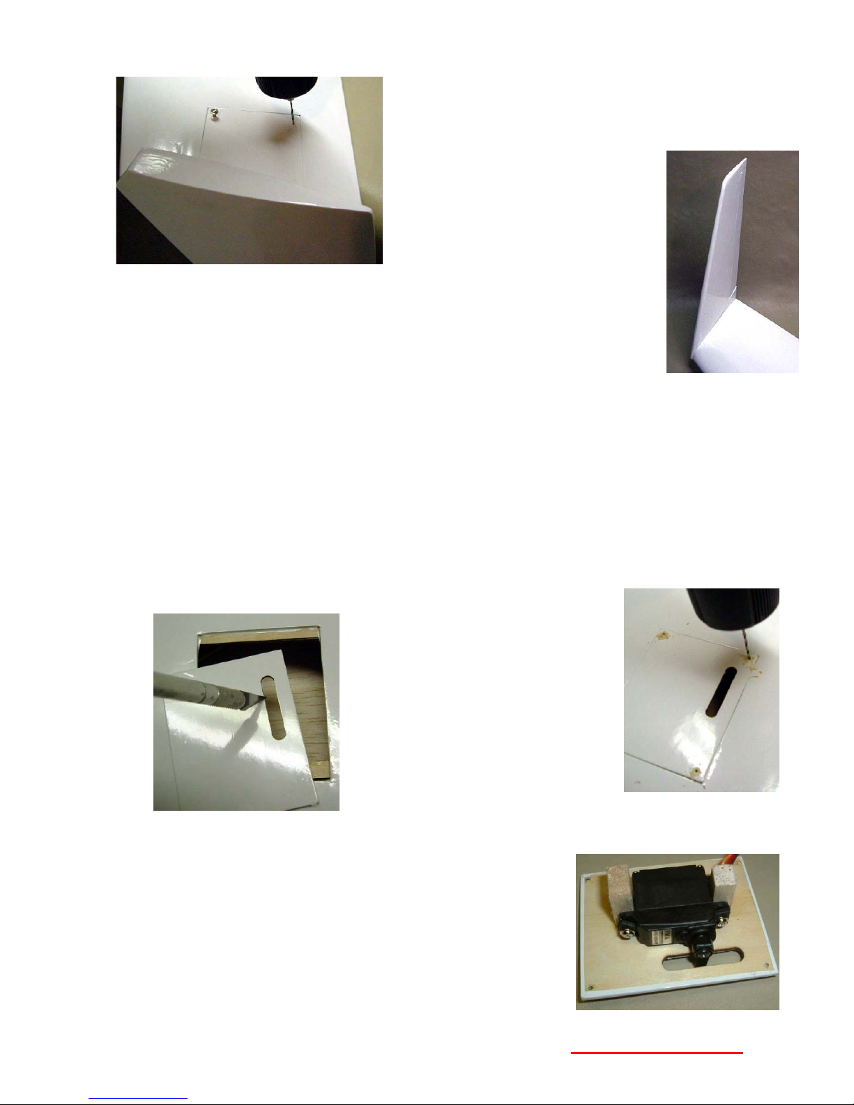
Installing the winglet servos
The winglet rudder servos are mounted on the inside/top face of the winglet plate to mounting
blocks. Verify that the servo arms are electrically neutral (Stick and trim centered, receiver shut
off before transmitter.) Use a single leg output arm or a two-leg arm with one leg cut off.
Read the notes below. Then start assembly using the steps that follow these notes.
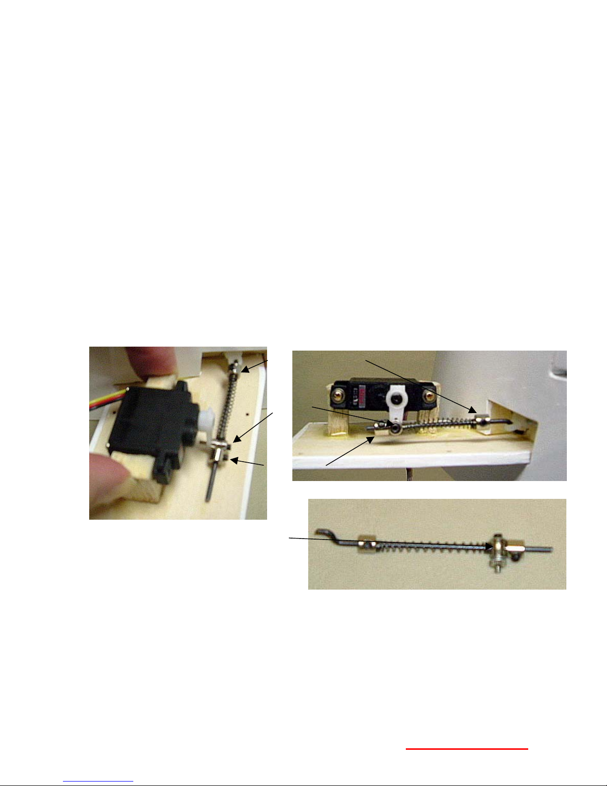
Operation of the servo saver: In one direction the barrel hits the collar and ‘pulls’ on the rudder
pushrod. In the other direction the barrel pushes against the spring, and allows the pushrod to
slide through the barrel as the servo arm rotates towards the winglet.
Notes:
Out-Board Collar
Barrel
In-Board
Collar
You can remove the setscrew in the end of
the barrel that normally clamps the rod to
the barrel (when this part is used to move
throttle linkages.) We will allow the rod to
slide through the barrel.
The servo must be high enough off the plate to allow the arm and barrel to clear the plate
beneath it. – but just barely.
Note how the servo is set towards the middle of the plate, away from the edge. No part of the
mechanism should be closer than 5/32” from the edge of the plate. This is to allow room for the
barrel protruding above the servo arm to clear the ply mounting surface inside the wing after it is
installed. Look at the winglet servo bay, at the end of the wing, and you’ll see how the ply is
notched away to allow some room.
The barrel should be against the inboard collar when the rudder and servo arm are centered.
You’ll adjust the inboard collar so that this is the case. The outboard collar is moved to adjust the
Experimental Aircraft Models
- 9 - WWW.RCHomebuilts.com

spring loading to keep the rudder centered. Compress the spring between the barrel and
outboard collar by about 1/4” after everything else is already set up and in position.
Begin Assembly:
1) Using the hardware supplied with the servo, test fit/position the rudder servo on the topside
of the winglet plate. Assume a maximum servo arm length of ½” as measured from the
center hole to the tip of the arm. Reference the pictures for the general arrangement.
2) While holding the servo in position squeezed between the blocks, apply thin CA to the base
of the blocks to hold them in place. (Picture at upper left)
3) Remove the servo and reinforce the bond with 5 Minute epoxy applied at the base of the
blocks as a fillet all the way around the base of the blocks.
4) Retrieve the Servo Saver (#38) and insert the Z bend into the Nylon Rod Pivot End. At the
other end insert the stud on the barrel into the servo arm from the top. Select a hole that is
between 3/8” and 7/16” from the center screw, insert the stud, and thread the knurled finger
nut up into place, leaving about ½ turn loose. (The Barrel must be able to rotate in the hole.)
Cut off any excess arm length. Secure with Loctite or thin CA.
5) Position and secure the servo in place using the screws supplied with the servo. If you are
dedicating these servos to the model, consider applying some thin CA between the blocks
and the servo, bonding the servo to the blocks – AFTER you’ve tested the operation!
6) Adjust the linkage so that when the servo is in neutral, the inboard collar is pressing against
the servo arm, and the spring tension keeps the rudder centered. Remove the servo arm
center screw, pull off the servo arm and cut off excess pushrod length. Reassemble.
7) Test the operation of the rudder with your Transmitter/receiver.
8) Plug a 36” servo cable extension on to the ruder servo cable. Clamp or tape the connection,
but remember the Winglets are removable if you should want to transport the wings without
them attached.
9) Snake the servo extension wire through the wing and out the root rib of the wing using the
monofilament pull string already inside the wing.
Notes:
a. We thoughtfully tack glued the string keeper to the inside rib at the tip to prevent the
string from getting lost inside the wing during shipment. It may be stuck on there
pretty good! Use a pair of needle nose pliers and pry/break it off.
b. You can’t tie a useful knot in the filament, so don’t even try! Pass the filament under
the plug, between two wires behind the plug and over the top of the plug, and then
wrap a piece of tape around the plug. This will trap the filament against the plug and
allow you to safely pull on the filament to pull the wire through.
c. You will be pulling the plug end through the center of a number of wing ribs. If you
get stuck, loosen the tension on the filament and rotate/shake the wing so the plug
can fall away from a rib that it may be caught on.
11) Test the operation of the rudder again with your radio.
12) Note on the topside of the winglet plates there are four laser cut holes. Using a pin, punch
through the covering to leave a mark on the bottom side showing where these holes are.
Experimental Aircraft Models
- 10 - WWW.RCHomebuilts.com
13) Position the winglet into place on the wing and
drill four 1/16” holes at the pin punches, through
the winglet plate into the plywood in the wing.
Watch to be sure you do not
pinch wires as you assemble
the winglet to the wing.
14) Secure the winglet in place
with four 2.3 x 12mm washer
head screws (#36)
15) Test the operation of the rudder again to be sure there is no interference
from the mounting plates in the wing.
Mounting Aileron Servos
For installing the aileron servos you can either unplug and remove the winglet from the wing, or
work on the wing with the winglet overhanging the edge of the workbench.
1) Locate the aileron servo bay cover on the bottom of the right wing and remove it
Note that the slots for the aileron servos are ‘outboard’ from the plane’s center line, and
are left and right (opposite) to each other. This is because the ailerons operate in
opposite directions.
Note also that the factory used clear tape that is pain to remove. Using the point of a
razor knife you can carefully lift an edge. If you dent the balsa surface, re-heating the
covering will make the dent disappear. If there is an adhesive residue it is easily removed
with ‘Goo Gone’ or VMP Naptha
2) Trim the slot opening of each servo cover with a sharp razor knife.
(Don’t use the soldering iron
trick, as it will show the melted
edge where it would be visible
from the bottom side of the
plane. When cutting with the
razor knife cut on the ‘push’
stroke – this will give a cleaner
edge.)
3) With the covers in place, drill a
1/16” (1.5mm) hole at each
corner. Make sure the cover is oriented properly and
that the slots are towards the wing tip. Test fit the covers in place with four 2.3mm x 6mm
washer head screws (#2), then remove and place a few drops of Thin CA into the holes in
the wing to dry and strengthen the threads.
The standard size servos are mounted directly to the bottom
of the servo bay covers. Mounting blocks are provided, or
your may use two sided adhesive foam tape.(Not supplied).
Verify that the servo arms are electrically neutral and you
are using the length of arm you intend to use. (Refer to your
Radio owners’ manual for techniques for centering the servo
arm.)
Experimental Aircraft Models
- 11 - WWW.RCHomebuilts.com
 Loading...