

Experimental Aircraft Models Glasair SII, Glasair III Assembly Manual
“Enhancing the Homebuilt Experience”
Radio Control Scale Model
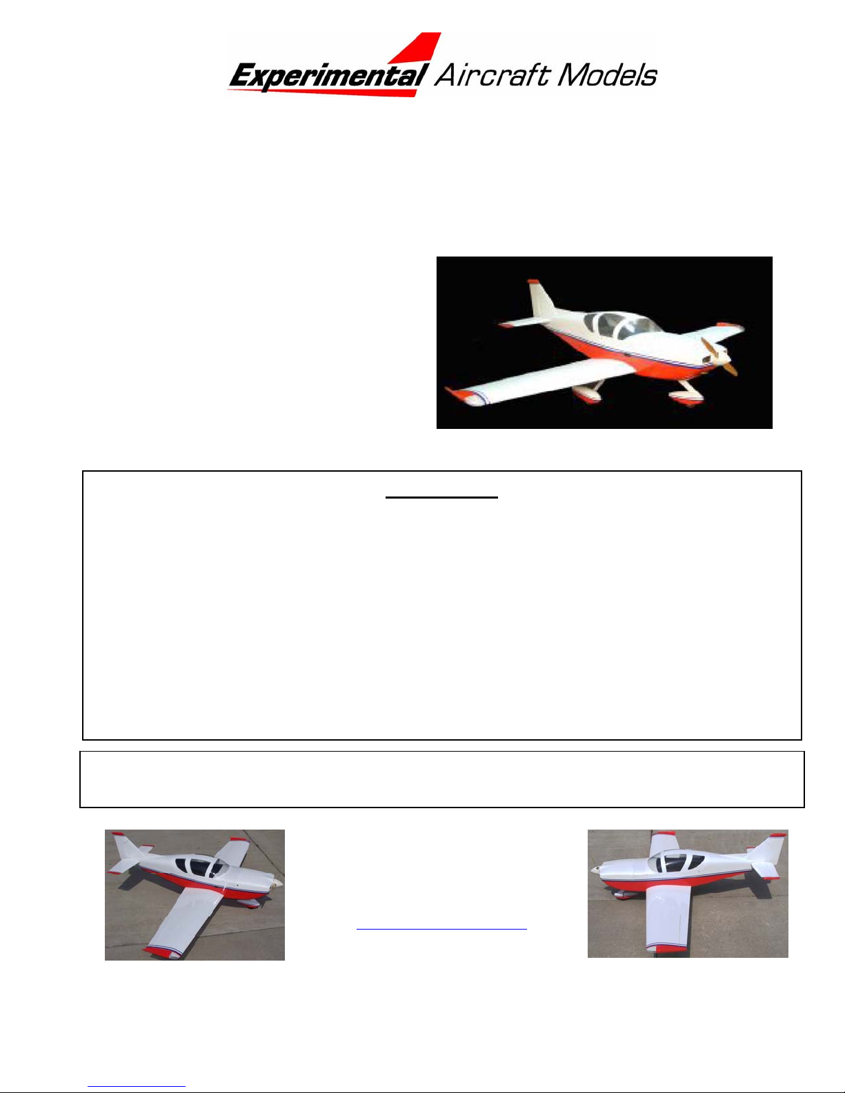
Glasair SII / Glasair III
Scale: 1= 3.5 (28% Full Size)
Wingspan: 80” (2032 mm)
Wing Area: 1024 in2 (66.1 dm2)
Flying Weight: 12 lbs (5.04 kg)
Wing Loading: 27 oz/ft
Length: 70” (1778 mm)
Radio: 5 Channels with 7 servos
Engines: 1.08 – 1.2 cu in 2 Cycle
1.20 – 1.4 cu in 4 Cycle
2
WARRANTY
Experimental Aircraft Models, LLC (EAM) guarantees this kit to be free from defects in material
and workmanship. The warranty does not cover individual parts damaged by modification or
abuse. In no case will EAM’s responsibility or liability exceed the original purchase price of the
kit. EAM reserves the right to change or modify this warranty at any time.
EAM assumes or accepts no liability for the manner in which this model aircraft is used by the
user, in any condition of assembly. By the act of purchasing this kit, the purchaser and any
subsequent user accepts full responsibility and all resulting liability.
If the purchaser is not willing to accept the above liability associated with the use of this
model aircraft, the purchaser is advised to return this kit immediately to the source from
where it was obtained.
Please read this manual thoroughly before starting assembly. It includes critical assembly
instructions and warnings in regards to the safe and enjoyable use of this scale aircraft model.
Experimental Aircraft Models LLC
1224 Amber Dr.
Thunder Bay, Ontario
Canada, P7B 6H7
www.rchomebuilts.com
ASSEMBLY MANUAL: Glasair SII / III
About Your Model: You have purchased 1 of a limited production run of Glasair SII /
III RC model kits in the world. You have a very unique model of an Experimental
aircraft. In the United States, ‘Experimental Aircraft’ are aircraft that
are 51% or more built by an individual (usually at home) and fly
under an FAA issued “Flight Permit”, rather than “Certification”.
During the past 20 years the most advanced designs in civil aviation
aircraft have come from the ‘Homebuilt’ arena where, without the
expense of certification and manufacturers liability insurance, aircraft
of amazing performance and safety could be designed and offered to the public.
In our mission to support the homebuilder with a scale model of an aircraft project that
may have consumed hundreds/thousands of hours to complete, we have brought
together full-scale aircraft kit airframe manufacturers with a state-of-the-art world class
ARF (Almost Ready to Fly) model manufacturer. Our intent is to provide as scale a
model as possible that is as ARF as possible - within the confines of limited production
run sizes and knowledge that a builder will likely customize to match their own aircraft.
In that sense, this product caters more to the full scale builders, and scale modelers,
than it does ‘out of the box’ flyers.
Some interesting details about the production of this model; We control the entire
process of the model construction, starting with the direct import of balsa logs from
Ecuador, to hand carving the fiberglass plugs and lay-up of the fiberglass components.
The canopy molds are also hand carved and the vacuum forming is all done ‘inhouse’. You get to make similar choices as the Glasair homebuilder: type and size of
engine, fixed gear or retracts, as well as many other
touches that customizes their personal aircraft, or
your model. In addition our Glasair SII / III model will
also accommodate a lighting kit in the wing tip
A final point: Because the model is so special and the volumes (by model standards)
so low, we need your help. We have tried our absolute best to get everything right the
first time. If there is something during the construction and flying of the model that you
feel could be done more easily or better, we’d like to know. This is how it’s done in the
full size experimental aircraft world, and we want to be sure that the same spirit is
carried on in smaller scale. Full scale Glasair builders are continually finding ways to
improve the full size aircraft, and there is no reason why modelers should not have the
same ability to contribute to a better product.
We sincerely appreciate your vote of confidence in purchasing our rendition of the
Glasair SII / III and truly wish you the best of enjoyment. Please feel free to e-mail us
with kit comments from our web site at www.rchomebuilts.com or call us toll free 888968-7251.
Andrew Kondor
Managing Director –
Experimental Aircraft Models, LLC
Page 2
ASSEMBLY MANUAL: Glasair SII / III
GENERAL ASSEMBLY NOTES – Before you Begin!
Congratulations on your selection of the Glasair for your aero modeling project! This
manual is written for modelers with some prior RC model building experience and
tools. There is always a question of how much detail should the manual include? If
something is unclear then please contact us for help. Similarly, your Glasair is
supplied with quality hardware, but some additional parts (listed below) are needed.
Again if you need some help in selecting what you need contact us.
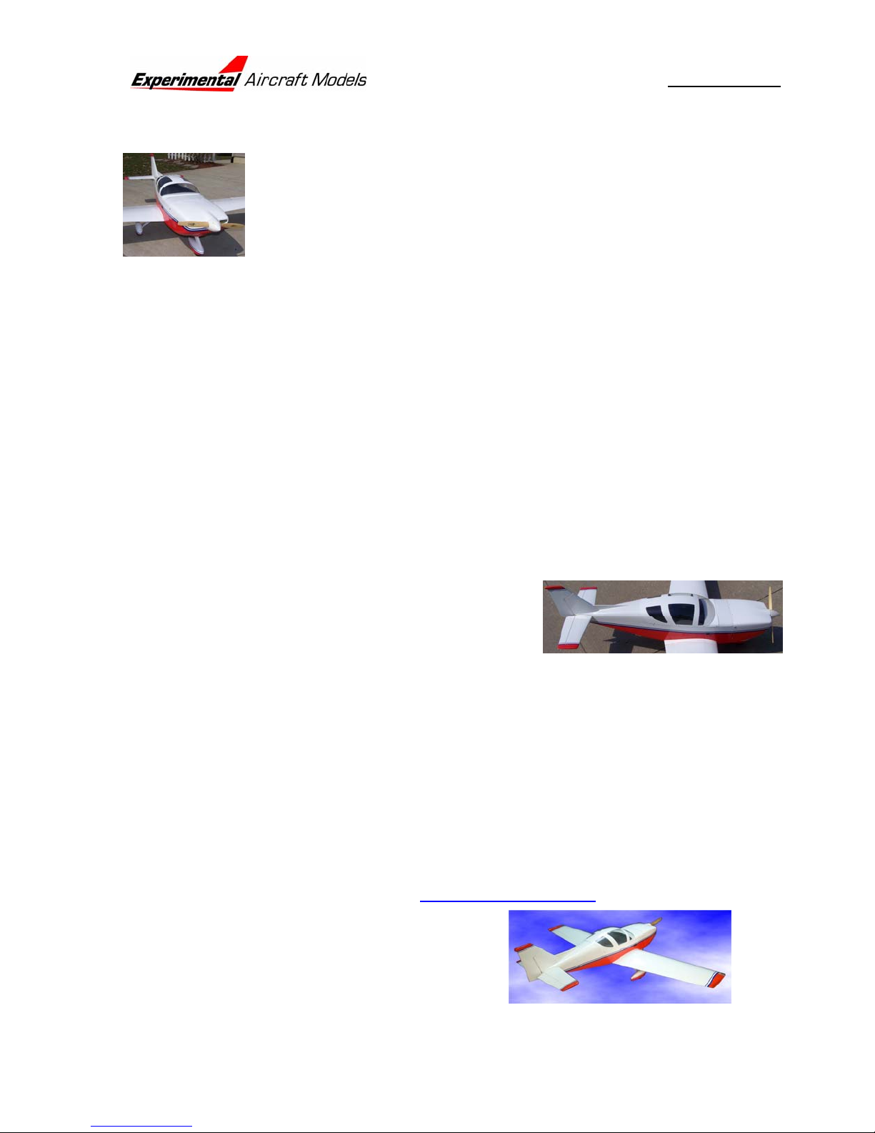
One of the first things to determine is exactly WHAT version of the Glasair are you
going to build? Just as the homebuilder customizes
their personal aircraft, your Experimental Aircraft
Models kit enables you to choose between the Fixed
Gear or Retract equipped Glasairs:
The Glasair S II or Super II line offers the RG
(Retractable Gear), the FT (fixed tricycle gear).
There is also the TD (Tail Dragger) variant – but
that is beyond the realm of your new EAM kit –
unless you want to customize!
All Glasair III’s have retractable gear
Thus if you build your model with a fixed trike gear it will be a Glasair SII-FT. If you
build it with the optional Robart retracts it will be either a Glasair III, or a Glasair Super
Page 3

ASSEMBLY MANUAL: Glasair SII / III
II RG! For the complete lineage of the Glasair series see their website at www.
glasairaviation.com. No matter what you call it you have your hands on a slick model
of a very impressive full size aircraft!
Please note that we use aircraft terminology in our
instructions. Specifically ‘Port’ is to Pilot’s left,
‘Starboard’ (or Strbd) is to Pilot’s right, ‘Forward’ is to
the front and “Aft” is to the rear. No matter how you may
have the model turned “Port” is always the left side of
the aircraft as the pilot sits in the cockpit facing forward.
A note about the covering - Your Glasair is covered in ‘Oracover’ – commonly known
as ‘Ultracote’ in the U.S. This is a high quality material, but through temperature
changes during shipping, the model may show wrinkles. This is normal. This
symptom is also more visible in that the model is fully balsa sheeted. The material can
easily be tightened by the application of heat from a hair dryer/heat gun or hot iron. If
using an iron, a piece of lightweight cotton (e.g. sheeting) placed between the iron and
the covering helps to even the heating. Pressing lightly will transfer the heat to the
covering, shrinking the material. Piercing a bubble with a pin and rubbing the hot area
with a cloth further helps remove the wrinkles.
Oracover is a very slippery finish that that resists adhesive bonding. It must be
removed from any joint to be glued. Failure to remove the covering from glue zones
will result in failure of the affected glue joint and likely damage or destroy your model.
The recommended engines are a 1.08-1.20 two stroke or 1.20-1.40 four stroke.
Experimental Aircraft Models discourages the use engines larger than this range. The
Glasair is an aerodynamically clean design that simply does not require larger than the
recommended engines. Some other notes on engines: most of
the engines in the recommended size range weigh roughly the
same - 28-34 ounces. Using a lighter engine will likely require
making up the difference with lead weight. Using a
larger/heavier engine might mean that lead will have to go in
the tail!
For 2-stroke engines the standard muffler will be very difficult –
or impractical to use because it will project way out of the cowl
and might also require modifying the firewall for clearance. For
this reason 2-strokes should be fitted with a side mount or “Pitts Style” muffler to keep
the installation simple and preserve clean line of the cowl. The mufflers on 4-strokes
are generally easier to package.
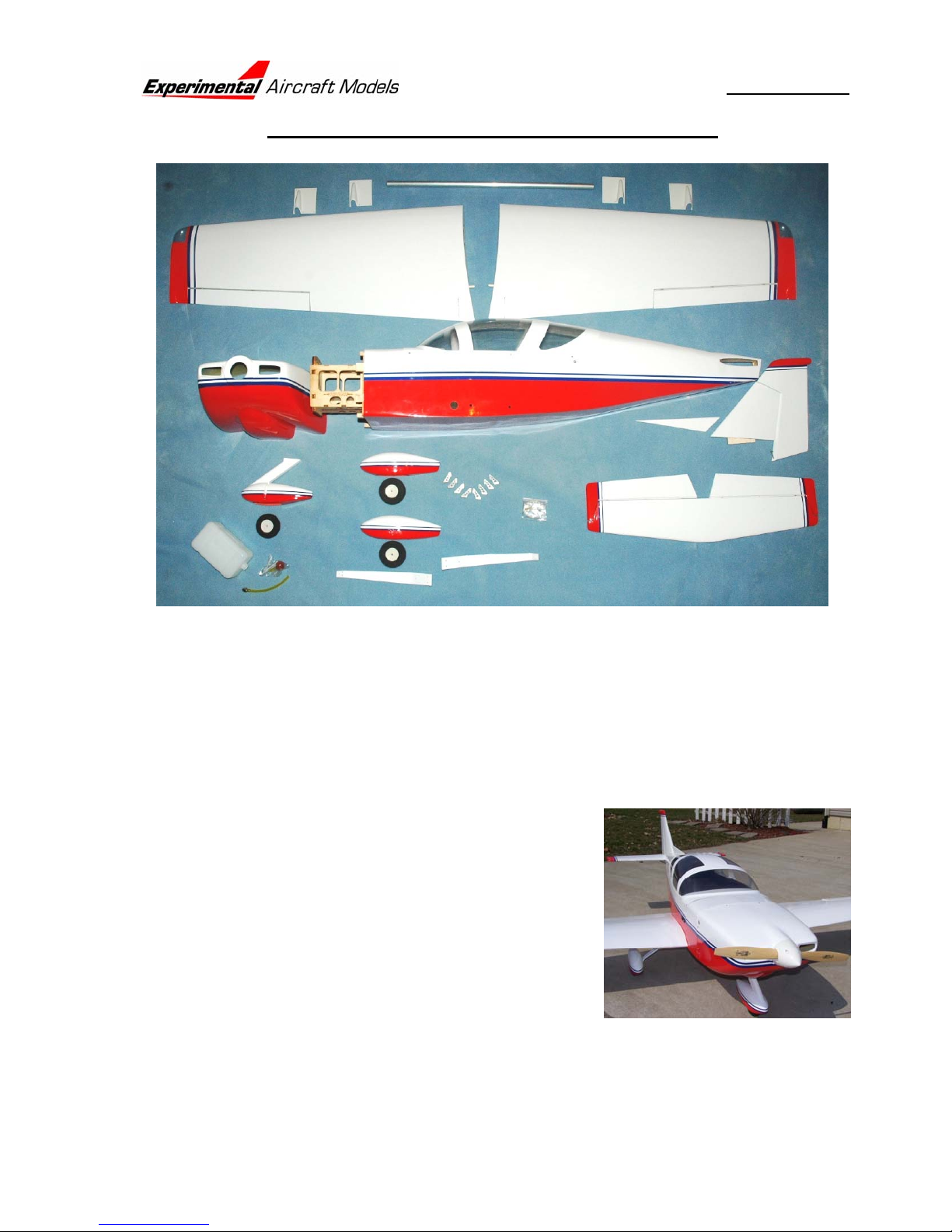
The Glasair is supplied with an assortment of hardware, but a lot of modelers have
their own preferences. A couple thoughts to keep in mind:
Keep close track of all the little screws and hardware sets located within all the
large component bags. It can be easy to misplace these items – not that WE have
Page 4

ASSEMBLY MANUAL: Glasair SII / III
ever done that! Collect these items in a medium size plastic container or zip-lock
bags to keep them safe until used. If you tag or mark them then you might even
remember where they came from!
The Glasair is supplied with METRIC hardware. Most hardware sold in America is
English. Unfortunately some of the English and metric hardware are just close
enough that they can be mixed – usually with disastrous results! Do not mix metric
and English thread fasteners, they WILL fail.
The supplied elevator and rudder pushrod clevis’ are 2mm and adequate for the
job at hand. However the Glasair is IMAA legal and if you fly it at an IMAA event
they will likely require that you have either 4-40 or 3mm size pushrod hardware.
The fixed-gear Glasair requires a 5 (or more) channel radio system with 7 standard
size servos. We like using ball bearing servos for their durability. Add retracts and
th
you need a 6
channel and at least one more servo. Technically the Glasair could be
flown with a 4-channel radio with 5 servos, with fixed gear, and the flaps locked in the
neutral position – but where’s the fun it that?
Additional components you may need from the hobby shop:
CA Adhesive (Thin)
CA Adhesive (Medium)
Epoxy (30 minute cure)
Silicone Seal/Adhesive
Heavy Duty Servo Lead Extensions (2) 450mm (18”) (for ailerons) with JR Plug
(recommended)
Heavy Duty Servo Lead Extensions (2) 150mm (6”) (for flaps) with Futaba Plug
(recommended)
(1) “Y”-Harness: Heavy Duty (for ailerons) with JR Plug (recommended)
(1) “Reversing” Y Harness: Heavy Duty (for flaps) with Futaba Plug
(recommended)
4-40 or 3mm Pushrod Hardware (optional, required for IMAA events)
Remote glow plug lighter (optional)
Fuel Filler valve (optional)
1 or 2 - Pilot Busts (optional)
Small jar fuel proof paint for under the cowl & touch-ups (optional)
Lighting Kit (optional, available from Kondor Model Products).
On the Y-harnesses: if you get one of them with the JR plug and the other with a
Futaba plug then they can be mated to the same style (either JR or Futaba) connector
on the Servo Extension end to prevent cross wiring. If both plugs are the same style,
then you will have to mark each lead with a “flag” identifying its purpose.
Page 5
ASSEMBLY MANUAL: Glasair SII / III
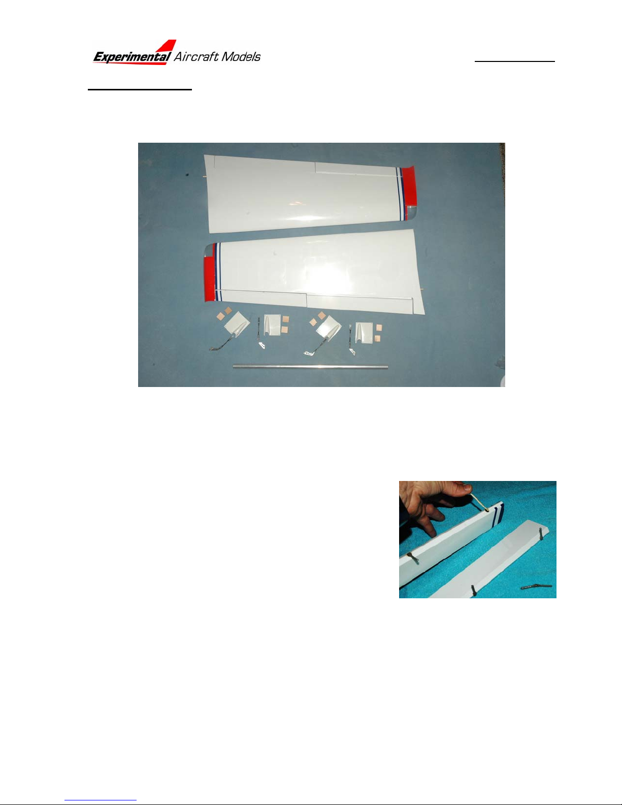
WING ASSEMBLY
The flaps are already hinged and ready to go; however the hinge points in the ailerons
must be installed. Next we’ll install the servos on their mounts, install the control horns
and linkages, wiring harnesses and finally install the servos in the wing.
Aileron Hinges
A “go slow” approach works best here. The best way to align the hinge points is to
epoxy them into just the aileron, then after the epoxy cures, epoxy the hinges to the
other surface.
1. Remove the aileron and remove all of the hinge points. Mix a small batch of epoxy
and using a toothpick drop some epoxy down into
each hinge pocket, hold the surface with the hole
pointing up so the epoxy can flow down into the
hole. Put a second drop in each pocket if needed.
One at a time, push the hinge points into their
pockets if the epoxy purges out of the hole, then
back out the hinge point, wipe the excess epoxy off,
then reinsert it. Inspect each hinge to see that it is
square to the surface. Then pivot the hinge, and
check again to see it is square. Press the surface
up against a straight surface to assure the hinges are all seated at the same depth.
Port Aileron Hinges Installed, Starboard Aileron Hinges Installed
2. When the epoxy is cured, carefully check the movement of each hinge point. You
may have to (carefully!) pop the movable end of the hinge point loose from any
stray epoxy that has gotten into it. Go slowly until each of the hinges moves freely.
Your servos and your battery pack will thank you!
Port Aileron, Starboard Aileron
Page 6
ASSEMBLY MANUAL: Glasair SII / III
3. Next step is to install the aileron to the wing. The hinge points do not bottom out
on the wing side, so it is important that the hinge pocket be wetted out nicely.
Install the hinge points onto the wing side, set the hinge gap to no more than 1 mm
(1/32”). A good way to do this is by using a thin piece of balsa or thin cardboard as
spacers to set the gap consistently. Use some tape on the aileron to hold the
position, and then try to set the wing up on its trailing edge while the epoxy cures.
That way, any excess epoxy pushed inside the wing should flow back and help lock
the hinge point in place.
Port Aileron, Starboard Aileron
Wing Servos
1. Locate the four servo covers and eight mounting
blocks. Note that two of the servo covers have the
pushrod slot offset to one direction and the other
two to the other direction. Rough-up the inside
surface of the servo cover with some sandpaper to
promote better adhesion of the servo mounting
blocks.
Servo Covers Sorted & Prepped 1, 2, 3, 4
2. Position the servo by centering the servo output
arm in the slot then use a spring clamp to hold it in
position. OPTIONAL: put a dab of silicone seal on
the servo before clamping the servo down; it will
help retain the servo but still allow the servos to be
popped off if needed for service. With the servos
clamped in position epoxy the mounting blocks in
close under the servo lugs.
Servos & Covers Clamped 1, 2, 3, 4
3. After the epoxy cures, drill a 1.5mm (1/16”) hole
through each grommet and screw the servos to the
mounting blocks.
Servo Cover 1, 2, 3, 4
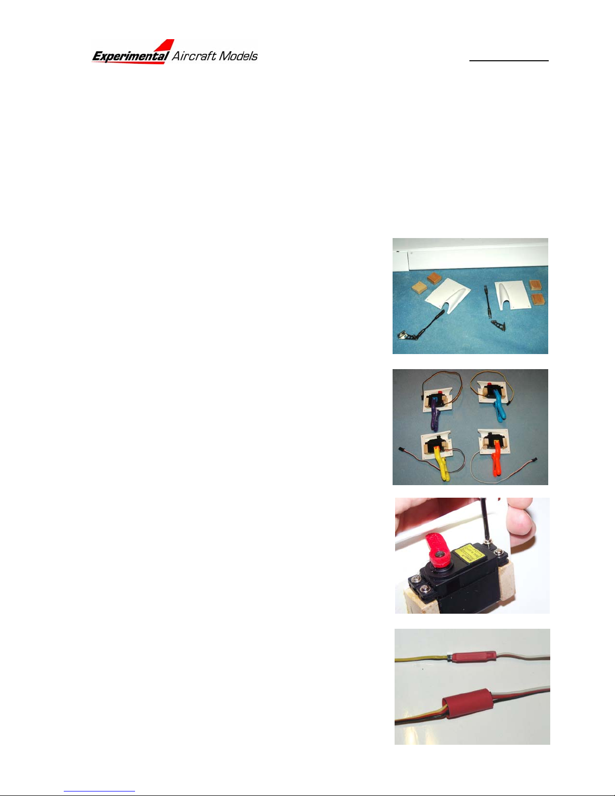
4. Next step will be to install the servo wire extensions.
Each Flap servo needs a 150mm (6”) extension,
each aileron a 450mm (18”) extension. Because
these will be out of sight inside the wing, it is
prudent to “safety” the connections. Shown here is
a piece of shrink wrap tubing over the connector
Page 7
y
ASSEMBLY MANUAL: Glasair SII / III
joint. Another possibility is to use electrical tape, We have even seen successful
installations that use a loop of dental floss to tie the connection together! How
ever you do it, make sure the connection is retained.
Now is a good time to double check the operation of the servos and harnesses
BEFORE you run the wiring through the wing! Use the Y-Harness for the aileron
servos and the reversing Y-Harness for the flap
servos so you can confirm the operation of the
complete harness before you install the wiring.
RECOMMENDED: for the aileron servos, remove
the output arms and displace them by rotating the
arms one or two splines FORWARD of the centered
position. This will provide differential throws
(ailerons will move UP farther than DOWN) and
somewhat reduce the need for rudder input when turning & banking.
The Reversing Y harness is the simplest means to get both flap servos moving the
same direction. Plug both flap servos into the Reversing Y, then - if needed remove the servo arm from one servo and reinstall it so it matches the position of
the other servo.
Port Flap Servo Extension Installed & Retained
Starboard Flap Servo Extension Installed & Retained
Port Aileron Extension Installed & Retained
Starboard Aileron Extension Installed & Retained
All Servos & Harnesses Checked for Operation
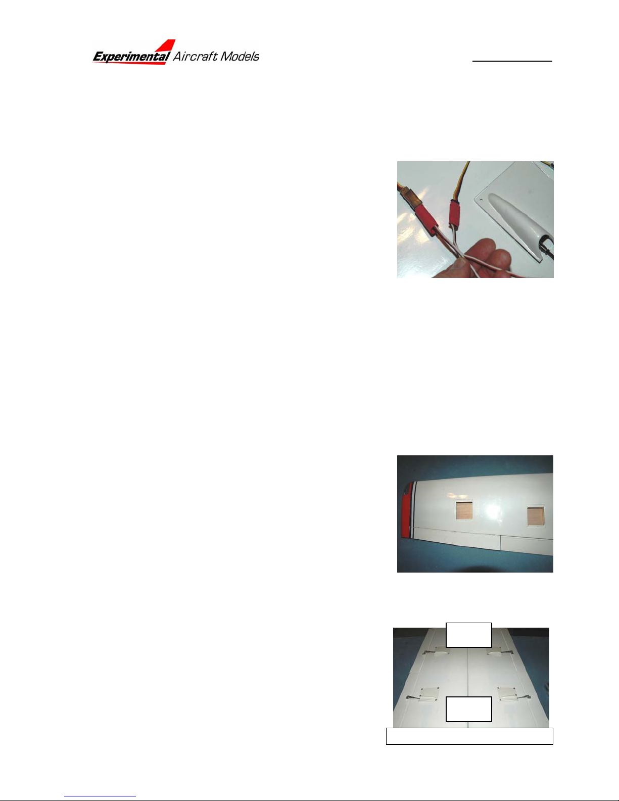
5. As shipped, the servo bays are covered over with
Oracover. Use a sharp modeling knife to open up
these bays, then use a trim iron to seal the edges of
the Oracover to the servo bays.
Port Wing Servo Bays Opened
Starboard Wing Servo Bays Opened
6. Next up is to route the servo wiring through the wing and get the servos in position
so we can install the control linkages. Find the pull through string in aileron servo
bay: it is wrapped and glued to a balsa stick. The
Aileron
other end is tacked inside the access hole in the
wing root. Remember that the correct servo pair
for each wing are the ones that when installed
orient the bottoms of the servos toward the wing tip
and the pushrod fairings both toward the wing root.
Securely tape the aileron servo extension plug to
Flap
Wing Root: Tops of servos point this wa
Page 8
ASSEMBLY MANUAL: Glasair SII / III
the little stick on the string. Keep it smooth and
torpedo-like to make it easier to slip through the
wing. Pull the lead through until it reaches the flap
servo bay. Tape the flap servo lead to the aileron
lead trying not to make the Torpedo any fatter – just
longer. Continue pulling on the string, pushing on
the harness, and jiggling the wing until the leads
com out at the wing root. For now it’s a good idea to
tape the leads to the wing root so they do not
inadvertently get pulled back inside the wing!
Port Aileron Servo Wiring Routed Through the Wing
Port Flap Servo Wiring Routed Through the Wing
Strbd Aileron Servo Wiring Routed Through the Wing
Strbd Flap Servo Wiring Routed Through the Wing
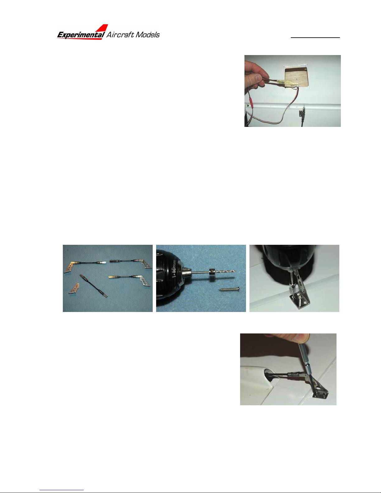
7. Assemble the clevis onto the aileron & flap links, and install each link onto a
control horn. Align the horn and link with the servo arm, align the horn as far
forward as possible WITHOUT overhanging the beveled edge, then drill a 2mm
(5/64”) hole for each control horn screw. NOTE: in order to prevent drilling through
the control surface use a drill stop. The middle picture shows a wheel collar
affixed over the drill bit to assure that the hole is drilled just as deep as needed for
the screw.
Port Flap Horn, Starboard Flap Horn Port Aileron Horn, Strbd Aileron Horn
8. Install the horns. With the rear-most screws, you
might want to cut off the excess screw length and
file off the burr – it looks better than that extra
screw point poking through on the top!
Port Flap Horn, Starboard Flap Horn
Port Aileron Horn, Starboard Aileron Horn
9. Drill out servo output arms to 2 mm (
Port Flap Servo, Starboard Flap Servo
5
/64”) to accept the wire pushrods.
Page 9
 Loading...