

Page 1

PORTABLE PD/CD-ROM
USER’S MANUAL
EXP COMPUTER, INC.
Page 2

EXP COMPUTER, INC.
FCC COMPLIANCE STATEMENTS
EXP MEMORY PRODUCTS.
NON-TRANSFERABLE LIMITED WARRANTY
EXP COMPUTER INC., AND EXP MEMORY PRODUCTS("EXP") warrants that the
Portable PD/CD-ROM (“products”) manufactured or distributed by EXP to be free
from failures due to defects in materials or workmanship for full one year from the
date of purchase of the products.
This warranty is void if the product is damaged by abnormal or improper use or by
accident, abuse or if any attempt to repair or modify the product without
authorization from EXP. Your sales receipt or invoice, showing the date of purchase
and the name of the authorized reseller, is your proof of the date of purchase.
During the warranty period, EXP will at its option, replace or repair, at no charge, the
product which in its opinion is defective.
Before you return the failed products, contact EXP. You must obtain a Return
Merchandise Authorization (RMA) number by calling EXP Computer Inc. At (516)
496-7629. The RMA number should be displayed on the outside of the returned
package and on the accompanying packing list. EXP cannot be held responsible for
any package returned without the RMA number. You are responsible for packaging,
providing proof of the date of purchase and the shipping cost of the failed product to
EXP Computer, Inc. You are responsible for mailing the warranty registration card.
The warranty claims may not be honored if there is no corresponding registration
card on file at EXP.
IN NO EVENT WILL EXP BE LIABLE FOR ANY DIRECT, INDIRECT, SPECIAL,
INCIDENTAL OR CONSEQUENTIAL DAMAGE, INCLUDING LOSS OF PROFIT,
LOSS OF SAVINGS; OR ANY OTHER DAMAGES CAUSED BY PRODUCT OR
FAILURE OF THE PRODUCT TO PERFORM.
THIS LIMITATION OF LIABILITY APPLIES EVEN IF EXP HAS BEEN ADVISED OF
THE POSSIBILITY OF SUCH DAMAGES. SOME SATES DO NOT ALLOW THE
EXCLUSION OR LIMITATION IN INCIDENTAL OR CONSEQUENTIAL DAMAGES,
SO THE ABOVE EXCLUSION OR LIMITATION MAY NOT APPLY TO YOU.
This equipment has been tested and found to comply with the limits for a
Class B digital device, pursuant to Part 15 of the FCC Rules. These limits
are designed to provide reasonable protection against harmful interference
in a residential installation. This equipment generates, uses and can radiate
radio frequency energy and, if not installed and used in accordance with the
instructions, may cause harmful interference to radio communications.
However, there is no guarantee that interference will not occur in a particular
installation. If this equipment does cause harmful interference to radio or
television reception, which can be determined by turning the equipment off
and on, the user is encouraged to try to correct the interference by one or
more of the following measures:
Reorient or relocate the receiving antenna.
Increase the Distance between the equipment and receiver.
Connect the equipment into an outlet on a circuit different from that to which
the receiver is connected.
Consult the dealer or an experienced radio/TV technician for help.
CAUTION
CHANGE OR MODIFICATIONS NOT EXPRESSLY APPROVED BY
PARTY RESPONSIBLE FOR COMPLIANCE COULD VOID THE
USER’S AUTHORITY TO OPERATE THE EQUIPMENT.
EXP TECHSUPPORT TEL: (516)-496-7629 WEB: WWW.EXPNET.COM
Page 3

TRADEMARKS
SystemSoft is a registered trademark of SystemSoft Corporation.
CardSoft is a trademark of SystemSoft Corporation.
Phoenix is a registered trademark of Phoenix Technologies, Ltd.
Databook is a registered trademark of Databook Inc.
Cardtalk is a trademark of Databook Inc.
PCMCIA is a trademark of Personal Computer Memory Card International
Association.
MS-DOS, Windows, Windows 95, and MSCDEX are trademarks of Microsoft
Corporation.
Photo CD is a trademark of Kodak.
CONTENTS
INTRODUCTION.............................................................................. 1
SYSTEM REQUIREMENTS....................................................... 1
FEATURES AND SPECIFICATIONS.......................................... 1
PART NAMES AND FUNCTIONS..................................................... 3
FRONT PANEL OF THE CD-ROM DRIVE ................................. 3
REAR PANEL OF THE CD-ROM DRIVE .................................... 4
POWER SOURCE............................................................................ 5
CONNECT THE AC ADAPTER.................................................. 5
INSTALLING THE BATTERIES.................................................. 6
REMOVING THE BATTERIES................................................... 7
NOTICE .............................................................................. 7
HARDWARE INSTALLATION........................................................... 8
SOFTWARE INSTALLATION .......................................................... 9
SOFTWARE INSTALLATION FOR WINDOWS 95 .................... 9
SOFTWARE INSTALLATION FOR DOS/WINDOWS 3.1........... 10
MANUAL INSTALLATION FOR DOS/WINDOWS 3.1 ................ 11
ENABLING 32-BIT CARD SUPPORT OF WINDOWS 95........... 13
PD TRAVELER’S DRIVE LETTERS ................................................. 15
FORMATTING PD CARTRIDGES.................................................... 16
USING THE PCMCIA CD-ROM WITH A COMPUTER...................... 17
HOW TO PLAY THE AUDIO CD ...................................................... 19
TROUBLE SHOOTING ..................................................................... 20
PCMCIA(PC CARD) SOFTWARE INFORMATION ........................... 24
POWER SAVING ............................................................................. 29
Page 4

INTRODUCTION
The PD TRAVELER brings in the latest mobile computing technology to
notebook computer users with portability and convenience. The PD
TRAVELER is a
• PD drive which reads and writes 664 MB optical phase-change
cartridges
• CD-ROM drive which reads CD-ROM discs and plays CD-Audio music
discs
• Back-up device to store data
Featuring flexible power options, the PD TRAVELER may operate on either
AC power or batteries. The PD TRAVELER is designed for both business
and entertainment solutions.
SYSTEM REQUIREMENTS
1. Notebook or desktop computer with a PC Card(PCMCIA 2.1) Type I, II or
III slot.
2. MS-DOS Version 6.0 or higher with MSCDEX.EXE (for DOS/Windows
users only) or Windows 95.
FEATURES AND SPECIFICATIONS
§ Complies with PC Card (PCMCIA 2.1) Standard
§ MSCDEX compatible
§ Easy-to-install device driver software
§ Data stored on PD cartridge is good for 30 years
§ Ultra slim PCMCIA Card
85.6 x 54.0 x 3.3 mm (Type I)
§ PD/CD-ROM Drive
Size: 164 x 250 x 50mm
Weight ≤ 1.35 Kg
§ PCMCIA power consumption: +5V/300 mA (Standby), +5V/500 mA
(max.)
§ Power source: 12V/1A AC adapter or batteries (1.5V AA size x 8)
§ Windows 95 Ready
§ CD-ROM Data capacity: 553MB( Mode 1) 635 MB (Mode 2)
§ Motorized front tray loading
§ CD format supports CD-Audio, CD-XA, CD-ROM mode 1 and 2, Multi-
session Photo CD, Video CD
§ Audio function: Headphone output jack with volume control, Audio line-in
jack
§ PD storage capacity: 664MB
§ PD data transfer rate: 518-1,141 KB/sec (average 6X)
§ PD average access time: 125ms
§ CD data transfer rate: 900KB/sec (6X)
§ Buffer: 256KB
Page 5
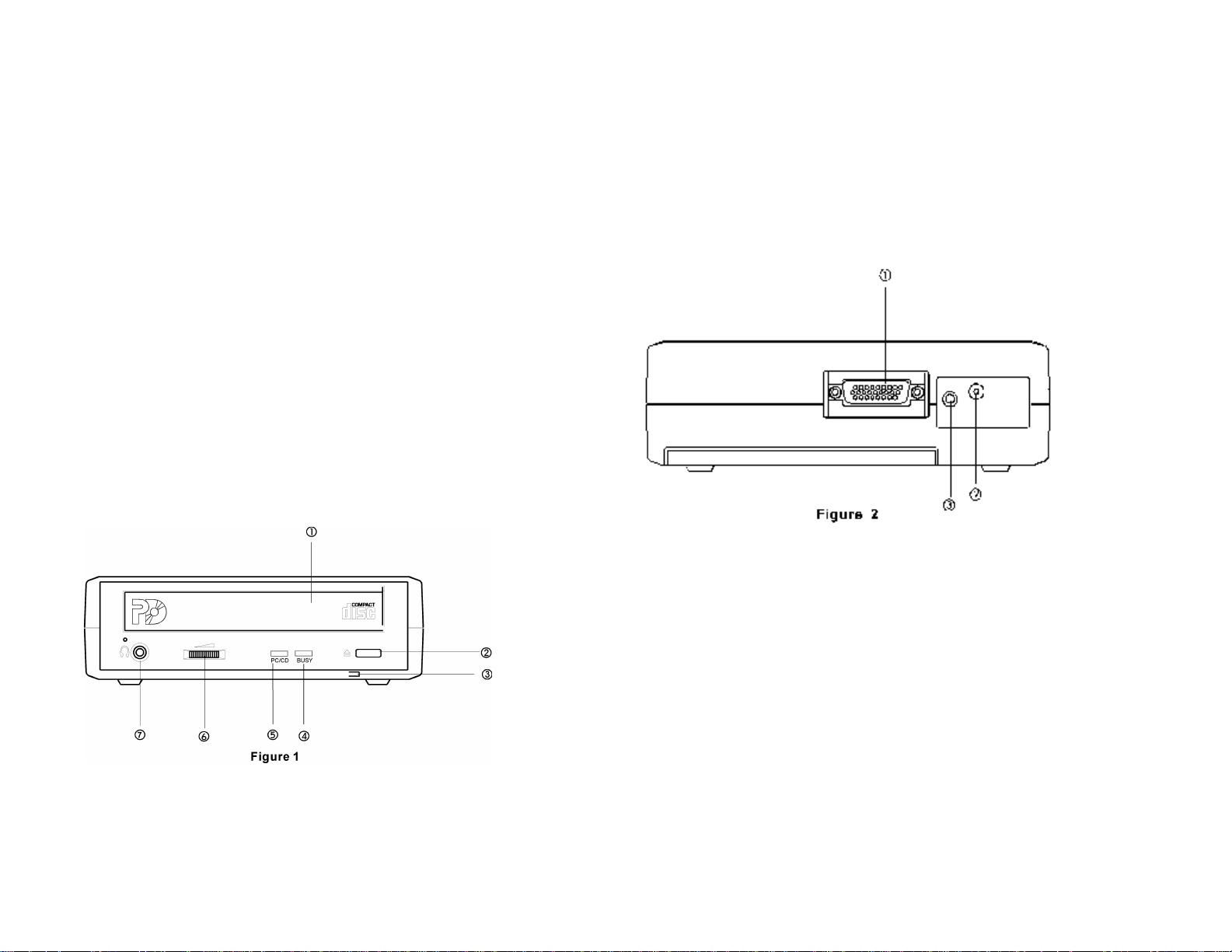
PART NAMES AND FUNCTIONS
FRONT PANEL OF THE PD/CD-ROM DRIVE
•• Disc Tray:
To insert the PD cartridge, CD-ROM or Audio CD.
‚‚ Load/Eject button:
Press this button to load the disc tray.
ƒƒ Power Indicator:
• This indicator will light with a green LED when the power is on.
• This LED will blink when battery power is low.
„„ Busy Indicator:
This LED will blink when the drive is busy reading or writing.
…… PD/CD Indicator:
• This LED glows amber when a PD cartridge is in the driver
• This LED glows green for a CD-ROM or Audio CD
• • This LED is dark when tray is empty
† † Headphone Volume Control Knob:
This rotary knob is used to adjust the volume of the headphone jack.
‡‡ Headphone Jack:
3.5mm audio headphone jack.
REAR PANEL OF THE CD-ROM DRIVE
•• Interface Connector:
This interface connector connects to the PCMCIA interface card.
‚‚ DC in Jack:
This jack connects to the AC adapter.
ƒƒ Line out Jack:
This jack outputs audio signal to an amplifier.
Page 6
POWER SOURCE
INSTALLING THE BATTERIES
The PD TRAVELER can be either powered by the AC adapter or by the
batteries as a flexible option. However, the AC adapter has a priority over
the battery in powering the PD/CD-ROM. That means if you connect the AC
adapter, the PD TRAVELER will operate on it regardless if the batteries are
installed.
The PD TRAVELER will be turned on automatically when your computer is
powered on and the PCMCIA interface card is connected to the computer
and initialized. On the other hand, when you turn off your computer or
disconnect the PCMCIA interface card from your computer, the PD
TRAVELER will be powered off automatically. Such convenient design
ensures that users will not waste the battery power if the CD-ROM is not in
use.
The POWER LED indicates the power state, it will always light up when the
power supply is in the normal condition. The LED will flash if the power is
insufficient caused by a malfunctioning AC adapter or if the batteries are
reaching the end their service life. In this case, remove the old batteries
and replace with new batteries, or check your AC adapter to see if it is
defective or improperly connected.
CONNECT THE AC ADAPTER
1. Connect the AC adapter plug to the DC IN jack at the rear panel of the
CD-ROM.
2. Attach the AC adapter to the AC power outlet.
The PD TRAVELER requires eight AA size batteries (not included) for
operation. When using alkaline batteries, the battery life may last for more
than 3 hours if the PD TRAVELER is used in CD-ROM mode, it can be even
longer when the PD TRAVELER is used in CD-Audio mode. You can also
use NiCad rechargeable battery’s which have a shorter service life. Both the
rechargeable battery and the re-charger are NOT provided with this unit.
To install the batteries, follow the instruction below:
1. Remove the disc from the PD.
2. Power off the PD by disconnecting the PCMCIA interface card from your
computer.
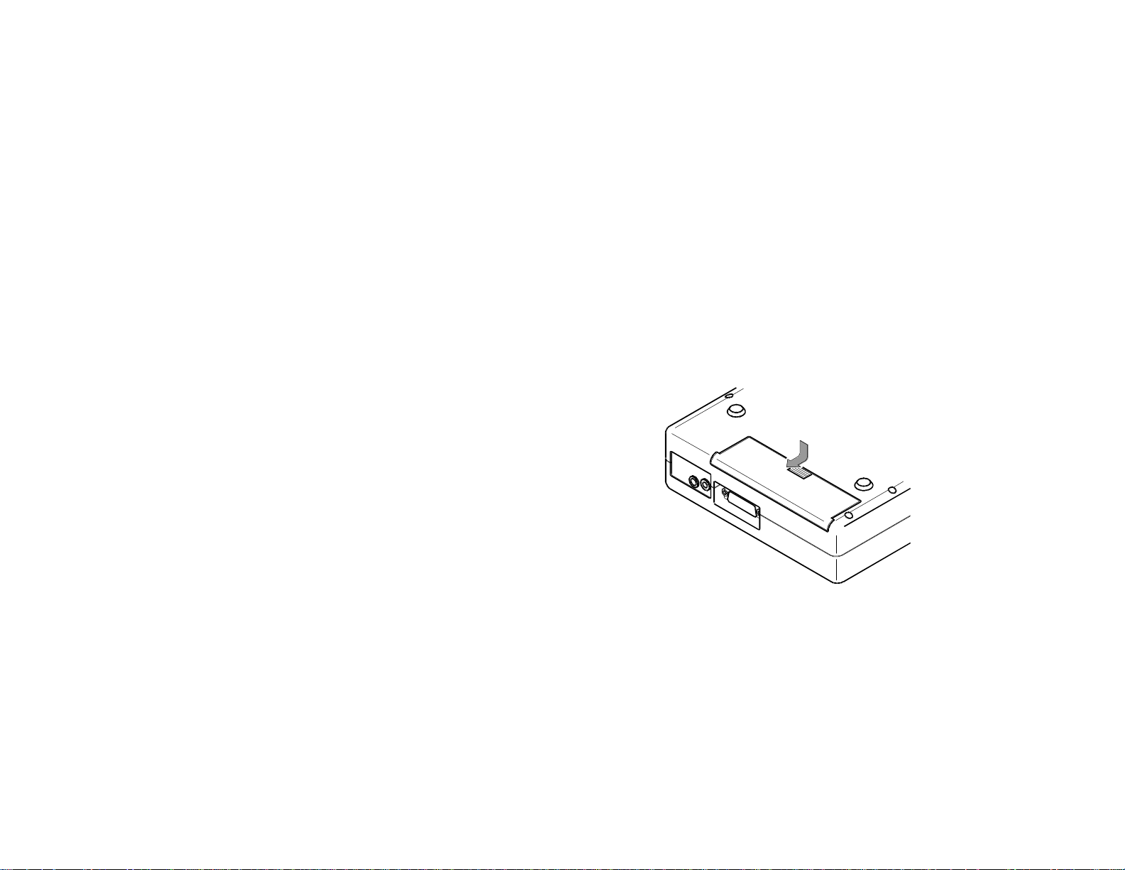
3. Turn over the PD drive and place horizontally.
4. Press and slide the battery lid in the direction of the arrow to remove it.
(As shown in Figure 3)
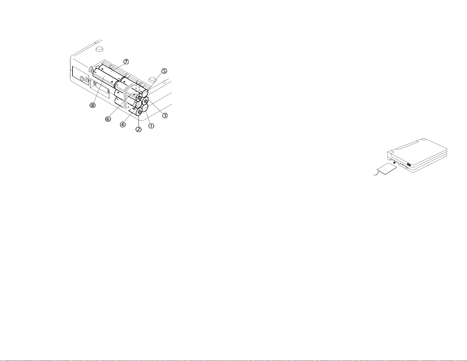
5. Install eight fresh AA batteries in the order as illustrated in Figure 4, and
make sure polarities are aligned properly. It is recommended that you
follow the order in the illustration to install the batteries with ease.
6. Please note that the battery ribbon must be arranged as shown in Figure
4. Otherwise, it will be difficult to remove the batteries.
7. Replace the battery lid.
Page 7
HARDWARE INSTALLATION
1. Connect the PCMCIA interface card to the CD-ROM drive. Press firmly
until the CD-ROM connector is seated, and tighten the two screws on the
cable connector.
2. Place the CD-ROM drive in the horizontal position. The CD-ROM is
designed to operate only in the horizontal position. Operating the CDROM drive in any abnormal position is not recommended.
3. Make sure that the cable of the PCMCIA interface card is firmly
connected to the interface connector at the back panel of the CD-ROM
drive.
4. Locate the PCMCIA slot of your computer or consult your computer user’s
manual for its location.
REMOVING THE BATTERIES
1. Remove the battery lid by sliding the cover in the direction of the arrow
as shown in Figure 3.
2. Lift up the battery ribbon to eject the batteries from the battery
compartment.
NOTICE
• Use only the AC adapter provided with this unit.
• If you will not use the unit with the AC adapter for a long period of time,
disconnect it from the AC power outlet.
• Do not mix old and new batteries, or different type of batteries (carbon
and alkaline, etc.)
• Always remove old, weak or worn-out batteries promptly and dispose of
them properly.
• If you will not use this unit for a long period of time, remove the batteries
and store them in a cool, dry place.
• Thoroughly clean the battery compartment before inserting new batteries.
5. Align the PCMCIA interface card with the
arrow sign pointing toward the computer’s
slot. (Please note that the card is keyed to
guide for proper insertion.)
Figure 5
6. Slowly insert the PCMCIA interface card into the slot and press firmly
until the connector is seated.
7. Turn the system ON to install the PD TRAVELER device driver. Please
follow the Software Installation procedures.
NOTICE
You should connect the PCMCIA interface card to CD-ROM drive first
before inserting the PCMCIA interface card into your computer. DO NOT
connect/disconnect the CD-ROM PCMCIA interface card to/from the CDROM drive when the system is in the power-on state.
Page 8
SOFTWARE INSTALLATION FOR WINDOWS 95
SOFTWARE INSTALLATION FOR DOS/WINDOWS 3.1
USING PD TRAVELER UNDER WINDOWS 95
The following dialog box will appear when you are using the PD TRAVELER
under Windows 95 for the very first time.
If the dialog box does not appear and the CD-ROM folder can not be found
in My Computer, please refer to the section titled “Enabling 32-Bit Card
Support”.
The INSTALL program helps you install the device driver into the computer
easily. Please follow the instructions below to proceed with automatic
installation.
1. Insert the device driver diskette into a floppy disk drive on your
computer.
2. Change the working directory to the floppy drive containing the
device driver diskette by typing “A:” or “B:” then press ENTER.
3. At the DOS prompt (A:\> or B:\>), type “INSTALL” followed by the
ENTER key.
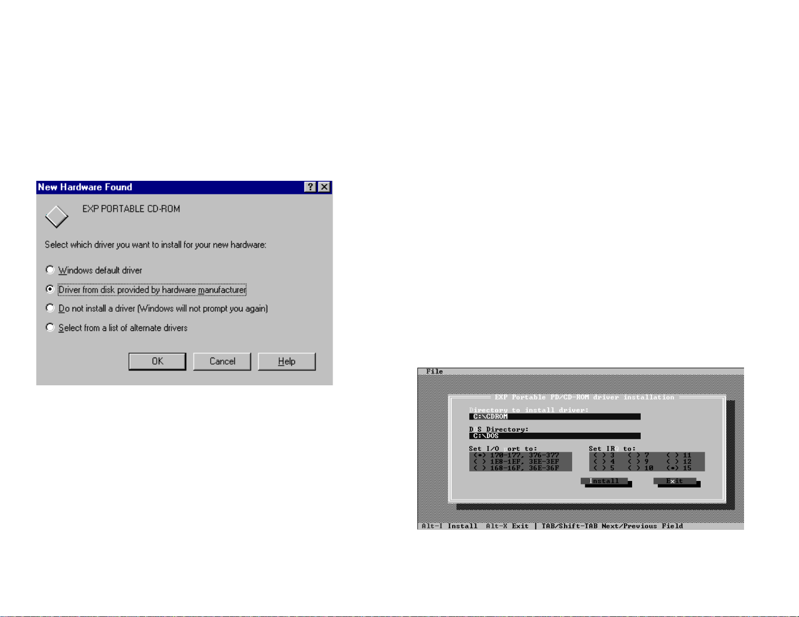
4. Press ENTER or click on the OK button to continue. When the
opening screen appears, a dialog box will be displayed for you to
specify the 1), directory to install the device driver; 2), the DOS
directory to specify the location of the MSCDEX driver, 3), the
I/O port and 4),the IRQ desired for the PD TRAVELER. Enter the
directory you select to install the driver and press the TAB key to
forward to the next field to indicate the DOS Directory. Press the
TAB key again to set the I/O port. The default setting of the I/O
ports are (170-177 and 376-377). After completing the selection,
click on the Install button to continue.
Figure 7
Select “Driver from disk provided by hardware manufacturer” and click on
OK button, Windows 95 will then prompt you to insert the manufacturer’s
installation disk. Insert the PD TRAVELER device driver disk into your
floppy drive. Specify the directory as A:\ or B:\ whichever containing the
diskette and select OK.
Follow the on-screen instruction to continue. After finishing, go to “My
Computer”, there should be two additional drive icons: a Removable drive
for the PD and a CD-ROM drive icon.
Page 9

MANUAL INSTALLATION FOR DOS/WINOWS 3.1
You may also manually install the PD/CD-ROM device driver if the default
setting conflicts with your system. Perform the following procedure to
complete the manual installation.
1. Copy the files EXPCDI.EXE and NTLPD.SYS from the device driver disk
to your hard disk.
/D is used to set the device name. It can be any name up to 8 characters.
This name must be the same as the name you will specify in the
MSCDEX.EXE option /D: name in the next step.
4. Add the following line at the TOP of your AUTOEXEC.BAT:
drive:\path\MSCDEX.EXE /D:MSCD001 /M:4
where drive:\path specifies the DOS directory or the directory containing the
file MSCDEX.EXE.
2. Add “LASTDRIVE=Z” to the TOP of your CONFIG.SYS file. If you already
have a LASTDRIVE line with a letter other than Z, change it to Z.
3. Add the following lines to the BOTTOM of your CONFIG.SYS file:
DEVICE=drive:\path\EXPCDI.EXE /P:1 /I:15 /D:MSCD001
DEVICE= drive:\path\NTLPD.SYS /P:1 /I:15
where drive:\path specifies the directory containing the file EXPCDI.EXE.
Note: If your CONFIG.SYS file is already loaded with PCMCIA software,
such as Cardsoft of SystemSoft or Cardtalk of Databook, it is necessary to
add the above line AFTER the PCMCIA software. Otherwise, the PCMCIA
interface card will not be initialized properly. To make sure if any PCMCIA
software has been loaded in your system and to know more about
PCMCIA(PC Card), please refer to the section titled “PCMCIA Software
Information”.
EXPCDI.EXE and NTLPD.SYS are the device driver for the PD Traveler.
The parameters are described as below:
/P is used to set the I/O ports, and the valid numbers are 1, 2, and 3. Each
number represents the I/O port pairs of (170-177, 376-377); (1E8-1EF,
3EE-3EF), and (168-16F, 36E-36F) respectively. The default setting is
/P:1.
Note: If your AUTOEXEC.BAT file loads a menu program such as
DOSSHELL or Windows, you have to add the above line to start your menu
program. Otherwise, MSCDEX will not have a chance to load before your
menu program begins.
The example above shows the default setting. The /D: switch indicates the
device name. It MUST be the same name as you specified by the /D:
switch of EXPCDI.EXE in your CONFIG.SYS file. The /M: switch indicates
how much memory to allocate for caching information on the CD-ROM. The
default /M:4 caches 8KB.
For more information about the switches of MSCDEX, please type “help
MSCDEX” at the DOS prompt.
5. Now, reboot your computer to activate the CD-ROM drive.
/I is used to set the IRQ number. The valid IRQs are 3, 4, 5, 9, 10, 11, and
15, and the default setting is /I:15.
Page 10

ENABLING 32-BIT CARD SUPPORT OF WINDOWS 95
Your system should be ready for PCMCIA socket support prior to operating
the PD TRAVELER. To check whether your computer is PCMCIA Socket
supported, first, double-click on the “System” icon from “Control Panel”
folder (you can select the “Control Panel” under “Settings” from the “Start”
menu to open the “Control Panel” folder).
Click on the Device Manager Tab. If “PCMCIA Socket” is found with a cross
(x) sign next to the PCMCIA Controller as Figure 9, it means the PCMCIA
device driver is not using 32-Bit Card Support.
Figure 10
After the PCMCIA 32-Bit Card support is installed, Windows will ask you to
reboot your computer. Then you should refer to the first section titled “Using
CD-ROM Under Windows 95” to configure the PD TRAVELER.
Figure 9
In this case, double click on the PCMCIA Controller, and a dialog box will be
displayed as below. Please place a check mark next to the current
configuration of Device usage box, then select OK.
If the PCMCIA Socket is not found, then you must add a PCMCIA socket to
your system. Please click on the “Add New Hardware” icon in the Control
Panel folder and select “PCMCIA socket”. Select the appropriate type of
PCMCIA Controller that matches with yours and follow the on-screen
instructions.
Page 11
PD TRAVELER’S DRIVE LETTERS
FORMATTING PD CARTRIDGES
Just as your existing disk drives are referred to by letters(A:, C:, etc.), PD
Traveler has two drive letters associated with it, one for PD, the other for
CD-ROM. For example, when using DOS/Windows 3.1, you may see
following message during boot-up:
.
PD is allocated 1 device(s) as D:
.
Drive E: = Driver MSCD001 unit 0
Under this example, DOS has assigned the PD to drive D and the CD-ROM
to drive E which are the next available letters in alphabetical order.
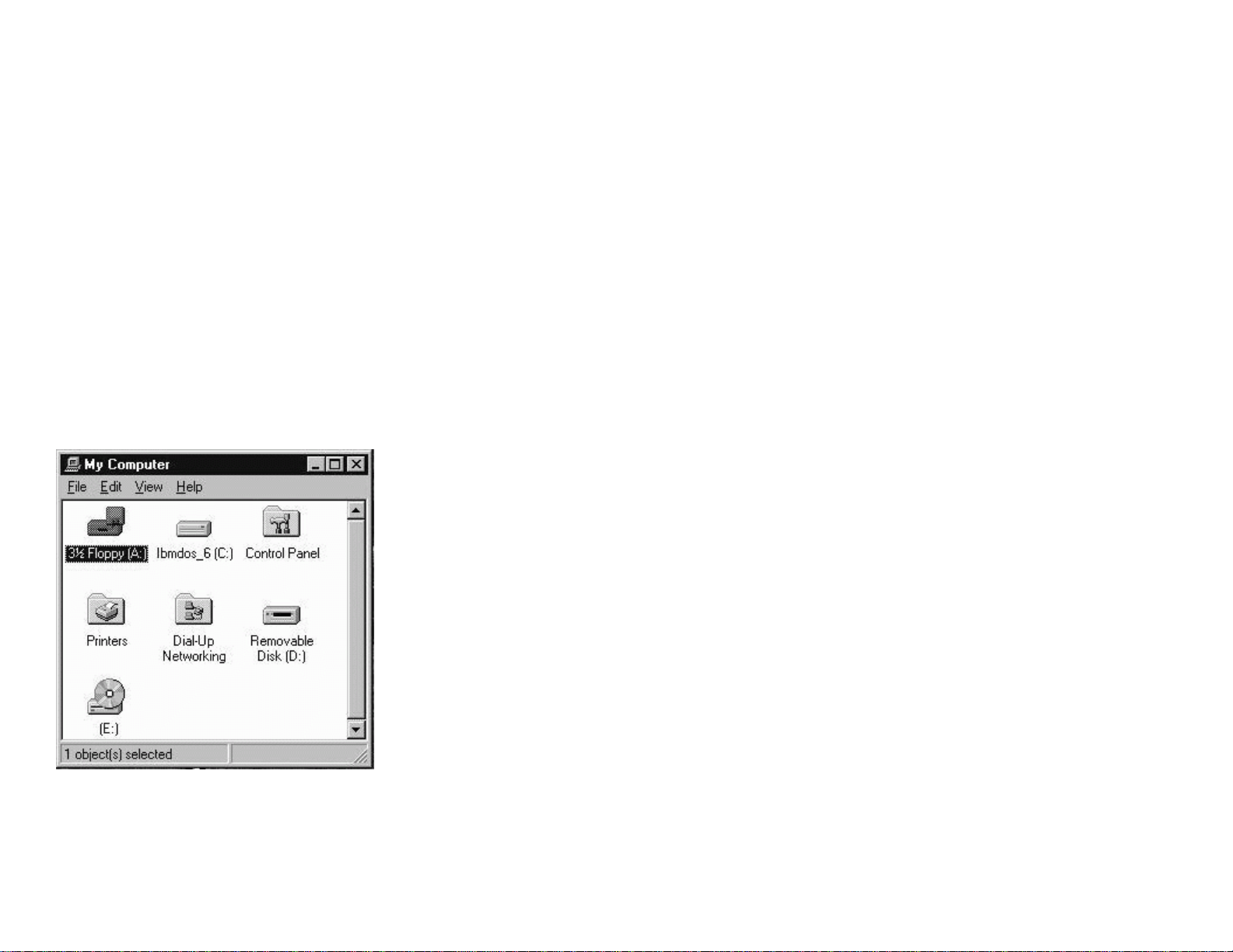
If using Windows 95, you can easily find the PD and CD-ROM under “My
Computer”. The figure 11 example has two drives icons at the bottom - the
Removal Disk(D:) and the Disk(E:), the D: is the PD and the E: is the CDROM drive.
Under Windows 95:
1. Insert a PD cartridge in PD Traveler
2. Click the mouse’s right button while point at the PD icon under “My
Computer”
3. Select Format and select any desired options
4. Press OK
Under DOS/Windows 3.1:
1. Insert a PD cartridge in PD Traveler
2. At a DOS prompt type the command FORMAT followed by the drive
letter for the PD
FORMAT D:
(If your PD driver letter is different, substitute that drive letter for the
letter D: instead)
NOTE:
If you format the PD cartridge, all the data on the PD will be erased.
FIGURE 11
Page 12

USING THE CD-ROM WITH A COMPUTER
Make sure the AC adapter is properly connected or the batteries are
installed.
CAUTION
Connect the PCMCIA interface cable to the CD-ROM drive before
inserting the PCMCIA interface card into your computer. DO NOT
connect/disconnect the PCMCIA interface cable to/from the CD-ROM
drive while the card is inserted and the system is in power-on state.
SETTING UP YOUR CD-ROM SOFTWARE
DOS/Windows 3.x
Most of the CD-ROM titles for Windows 3.1/3.11 contain the SETUP.EXE or
INSTALL.EXE program in the CD disc. You need to start either one of the
programs to add a Program Group and its icons into your computer, and
perform the following,
1) In Program Manager, click “File” then click “Run”
2) Type in D: (or the drive letter assigned for CD-ROM) SETUP.EXE or
INSTALL.EXE.
3) Follow the on-screen instructions.
4) After complete setting up, click the icon for the program.
The other procedure is from ‘Control Panel.’ Click on ‘Add/Remove
Programs’ icon, click on the ‘Install’ button then follow the on screen
instructions.
NOTE:
While operating the CD-ROM, the speed of your computer’s CPU and
display card will dominate the overall performance, especially when playing
full motion video. Slow display speed often causes “still frames”. In our
testing, some computers are capable of performing as high as 15
frames/sec; however, some can only achieve 2 frames/sec.
Windows 95
The CD-ROM for the Windows 95 titles include the AUTO RUN feature.
This means when you close the disc cover with this type of CD disc inside,
Windows 95 will start the opening screen automatically. You can add the
program, browse content of the CD, etc. from this screen.
Page 13

HOW TO PLAY THE AUDIO CD
Windows 3.1
The CD-Audio CDs can be played on your PCMCIA CD-ROM by using CD Audio
software utilities, such as the Media Player in Windows 3.1. To use Media Player,
you must have the [MCI] CD Audio driver installed. Make sure the CD-Audio disc
is installed in the CD-ROM drive. The CD Audio driver is installed through the
Control Panel. Go into the Drivers and ADD [MCI] CD Audio. The installation
will require one of the Windows diskettes to install the driver.
The driver file name is MCICDA.DRV. This should be in the System directory.
The system.ini should then have the driver listed in the section
[mci]
CDAudio=mcicda.drv
The mplayer.ini should have:
[Options]
CDAudio=62
[Devices]
CDAudio=2553, CD Audio
TROUBLE SHOOTING
Windows 95
The Windows 95 32-bit mode plug-n-play drivers will automatically allocate
the hardware resources for PD TRAVELER, therefore, you do not need to
choose the I/Os during the installation. However, if the system is not working
properly you still can select the I/Os by proper procedures. Be sure you have
the card inserted before doing the configuration change.
1. Go to “Control Panel”
2. Double click at “System” icon
3. Select “Device Manager”
4. Click at “Hard Disk Controller” and highlight “EXP Portable PD/CDROM”
Windows 95
Click on “Start” button then choose ”Programs”, then “Accessories”, then
“Multimedia” then click on the CD Player Icon.
If you do not have the Accessories Group or Multimedia Group, the options may
have not installed during Windows 95 set up. Click the Start button, go to Setting
=> Control Panel click on Add/Remove Programs then Windows Setup Tab. Place a
check mark on the box for missing programs and Windows 95 setup will install the
CD Player for you.
Page 14

5. Double click at the device you choose and select the “Resource” at the
pop-up windows, uncheck the “use automatic settings”
6. You can change the I/Os or IRQs by clicking at them
7. Make sure the “Conflicting device list” shows “No conflicts”.
8. Click “OK” when finishing, system may ask you to reboot the computer
to enable the new settings
Remove or re-install the driver
If you want to remove, re-install or upgrade the driver you have installed,
you need to remove the old driver first which can be done by highlighting the
EXP device driver under “Device Manager”, then click at “Remove” button.
DOS/Windows3.X
After rebooting your computer, the following messages will be displayed on
your screen, which are generated by EXPCDI.EXE, NTLPD.SYS and
MSCDEX.EXE.
Configure card to:
I/O Port:170-177, 376-377
IRQ Number: 15
Device Name: MSCD001
EXP portable PD/CD-ROM card is present in socket 1
PD/CD-ROM (PD) Device Driver [Version 1.00]
PD is allocated 1 device(s) as D:
.
.
.
C:\DOS\MSCDEX.EXE /D:MSCD001 /M:4
MSCDEX Version 2.25
Copyright © Microsoft Corp. 1986-1991.
Drive E: = Driver MSCD001 unit 0
If any error occurs or the PD TRAVELER does not work, you should reboot
your computer again. When the system displays 'Starting MS-DOS...', press
the F8 key to make the system executes the CONFIG.SYS and
AUTOEXEC.BAT step by step, so that you can consistently press the ‘Y’ key
to see each command's message. You can always run the INSTALL.EXE to
change the I/O port and IRQ setting.
Error messages generated by EXPCDI.EXE:
v v Error: PCMCIA card is not present!
If the above message appears, it means EXPCDI.EXE can't find any
PCMCIA card in your PCMCIA slots. Make sure the card is inserted firmly.
v v Error: Illegal I/O port!
The above message means invalid I/O ports in the EXPCDI.EXE line of
CONFIG.SYS has been selected. The legal I/O port numbers are: 1, 2, and
3.
v v Error: There is no available 4K memory for mapping!
The above message means EXPCDI can't find available 4K memory
between C000:0 to EFFF:0. This error can be corrected by changing the
EMM386 line of CONFIG.SYS to exclude at least 4K memory for mapping.
For example,
DEVICE=C:\DOS\EMM386.EXE ... X=D000-D3FF
v v Error: The INTEL 82365SL PCMCIA controller is not
detected in your system. You should contact your
dealer to get PCMCIA support software.
The above message means the PCMCIA controller for your system is not
INTEL 82365SL compatible. In this case, you should install PCMCIA support
software which should be supplied by the notebook manufacturer.
v v CD-ROM Drive is not found!
The above message means EXPCDI.EXE can't find the PD TRAVELER
drive. Please make sure the CD-ROM drive is properly connected to the
Page 15

PCMCIA interface card cable and the power cord is connected(or batteries
are loaded).
PCMCIA(PC CARD) SOFTWARE INFORMATION
Error message generated by MSCDEX.EXE:
v v Device driver not found: 'MSCD001'
This means that EXPCDI.EXE is not installed properly or you have entered a
different /D: switch in the MSCDEX line of AUTOEXEC.BAT. The /D:
switch must be the same as the /D: switch in the EXPCDI.EXE line of
CONFIG.SYS.
If the error message displayed is none of the above, please contact EXP
customer support at (516)-496-7629 or our Internet On-Line Technical
Support at http://www.expnet.com.
If you have installed the PCMCIA software, such as SystemSoft’s CardSoft
or Databook’s Cardtalk, then EXPCDG.EXE will call this PCMCIA software
to enable the card. If you don’t have one, the EXPCDG still can directly
access your hardware to enable the card. In this case, your computer should
have an Intel 82365SL Personal Computer Interface Controller (PCIC) or
another compatible controller.
PCMCIA software contains several components: Socket services, Card
Services, Resource Initialization Utility and Card Installation Utility. The
remainder of this section will explain the four components and list the device
driver names for the major PCMCIA software.
Socket Services provide the interface between a system’s BIOS and the
host controller chips (such as the Intel 82365SL PCIC, Vadem 468, etc. )
Socket Services includes functions such as configuring a socket for an I/O or
memory interface and controlling socket power voltages. The Socket
Services driver you have varies with the host computer chip of your
computer.
Card Services provides the interface between the PC Card and the PCMCIA
sockets. Card Services must be aware of the I/O, IRQ, and memory
resources already used by the system so it can accurately assign unused
resources to the PC Cards.
To ensure Card Services will operate reliably regardless of the system it is
installed on, some PCMCIA software provides its own resource initialization
utility, which will check I/O ports, IRQs, and memory addresses and then
report that information to Card Services.
Page 16

The Card Installation Utility detects the insertion and removal of PC cards,
and automatically determines the card type upon insertion so the card and
socket will be configured properly.
The device driver names of the major PCMCIA software are listed below:
Software/Device
Driver
Socket Services SS365SL.EXE,
Card Services CS.EXE PCMCS.EXE PCCS.EXE IBMDOSCS.SYS
Resource
Initialization Utility
IDE/ATA Driver ATADRV.EXE PCMATA.SYS
SRAM Card Driver MTSRAM.EXE
Flash Card Support MTAA.EXE,
Memory Card Driver MEMDRV.EXE
Card Installation
Utility
Card Services Power
Management
SystemSoft
CardSoft
SS365LP.EXE,
SSCIRRUS.EXE,
SSDBOOK.EXE,
SVADEM.EXE,
SSVLSI.EXE
CSALLOC.EXE PCMRMAN.SYS PCRM.EXE DICRMU02.SYS
MTAB.EXE,
MTI1,EXE
MTI2P.EXE
CARDID.EXE PCMSCD.EXE PCENABLE.EXE AUTODRV.SYS
CS_APM.EXE $ICPMDOS.SYS
Phoenix Award
Cardware
PCMSS.EXE SSPCIC.EXE IBMDSS02.SYS
IBM
ThinkPad
If you are not sure which PCMCIA software you are using, you may check it
by typing TYPE CONFIG.SYS at the DOS prompt followed by the ENTER key.
The file should come up and look like one of the following examples.
Page 17

SYSTEMSOFT PCMCIA SOFTWARE SAMPLE CONFIG.SYS FILE
LASTDRIVE=Z
DEVICE=C:\DOS\HIMEM.SYS
DEVICE=C:\DOS\EMM386.EXE NOEMS X=D000-D3FF
FILES=40
BUFFERS=20
STACKS=9,256
DEVICEHIGH=C:\CARSOFT\SS36SSL.EXE
DEVICEHIGH=C:\CARDSOFT\CS.EXE
DEVICEHIGH=C:\CARDSOFT\CSALLOC.EXE
REM** The REM’s should be removed from the following
REM** lines to enable memory and hard drive card support
REM** DEVICEHIGH=C:\CARDSOFT\ATADRV.EXE
REM** DEVICEHIGH=C:\CARDSOFT\MTSRAM.EXE
REM** DEVICEHIGH=C:\CARDSOFT\MTDDRV.EXE
DEVICEHIGH=C:\CARDSOFT\CARDID.EXE
DEVICE=C:\CDROM\EXPCDI.EXE /P:1 /I:15 /D:MSCD001
DEVICE=C:\CDROM\NTLPD.SYS /P:1 /I:15
PHOENIX PCMCIA SOFTWARE SAMPLE CONFIG.SYS FILE
LASTDRIVE=Z
DEVICE=C:\DOS\HIMEN.SYS
DEVICE=C:\DOS\EMM386.EXE NOEMS X=D000-D3FF
DOS=HIGH, UMB
STACKS=9,256
DEVICE=c:\PCMPLUS3\CNFIGNAME.EXE/DEFAULT
DEVICE=C:\PCMPLUS3\PCMSS.EXE
DEVICE=C:\PCMPLUS3\PCMCS.EXE
DEVICE=C:\PCMPLUS3\PCMRMAN.EXE
DEVICE=C:\PCMPLUS3\PCMSCD.EXE
DEVICE=C:\CDROM\EXPCDI.EXE /P:1 /I:15 /D:MSCD001
DEVICE=C:\CDROM\NTLPD.SYS /P:1 /I:15
DEVICE=C:\CDROM\NTLPD.SYS /P:1 /I:15
IBM PCMCIA SOFTWARE SAMPLE CONFIG.SYS FILE
LASTDRIVE=Z
DEVICEHIGH=C:\DOS\HIMEN.SYS/TESTMEM:OFF /MACHINE:2
DEVICEHIGH=C:\DOS\EMM386.EXE NOEMS X=D000-DFFF
BUFFERS=40
FILES=40
STACKS=9,256
DOS=HIGH
DEVICEHIGH=C:\THINKPAD\IBMDSS02.SYS /S0=2
DEVICEHIGH=C:\THINKPAD\IBMDOSCS.SYS
DEVICEHIGH=C:THINKPAD\DICRMU02.SYS /MA=D000-DFFF
DEVICEHIGH=C:\THINKPAD\$ICPMDOS.SYS
DEVICE=C:\THINKPAD\AUTODRV.SYS C:\THINKPAD\AUTODRV.INI
DEVICE=C:\CDROM\EXPCDI.EXE /P:1 /I:15 /D:MSCD001
DEVICE=C:\CDROM\NTLPD.SYS /P:1 /I:15
AWARD PCMCIA SOFTWARE SAMPLE CONFIG.SYS FILE
LASTDRIVE=Z
DEVICE=C:\DOS\HIMEN.SYS
DEVICE=C:\DOS\EMM386.EXE NOEMS X=D000-D3FF
FILES=40
BUFFERS:20
STACKS=9,256
DEVICE=C:\CARDWARE\SSPCIC.EXE
DEVICE=C:\CARDWARE\PCCS.EXE
DEVICE=C:\CARDWARE\PCRM.EXE/AUTODETECT
DEVICE=C:\CARDWARE\PCENABLE.EXE
DEVICE=C:\CDROM\EXPCDI.EXE /P:1 /I:15 /D:MSCD001
Page 18

POWER SAVING
The PD TRAVELER may operate with an AC adapter or batteries. Use of
the supplied AC Adapter will provide the power for use as a portable CD
player, or to extend the computer’s battery life.
The PD TRAVELER drive will automatically enter the sleep mode (spindle
off) when it has not been accessed for about 5 minutes. Also, you can
manually get to the sleep mode by removing the Compact Disc (CD) from
your CD-ROM drive. The operating current will then be reduced to 120 mA.
NOTE:
DO NOT disconnect the PCMCIA card from your CD-ROM drive while the
computer power is ON.
 Loading...