

Page 1

3Com
®
Corporation
PathBuilder™ S200 Series Switch
Bridging
Page 2

Notice
©
1998 3Com Corporation
5400 Bayfront Plaza
Santa Clara, CA 95052-8145
(408) 326-5000
All rights reserved.
Printed in U.S.A.
Portions reprinted with the permission of Motorola, Inc.
Restricted Rights Notification for U.S. Government Users
The software (including firmware) addressed in this manu al is provided to the U.S.
Government under agreement which grants the government the minimum “restricted rights”
in the software, as defined in the Federal Acquisition Regulatio n (FAR) or the Defense
Federal Acquisition Regulation Supplement (DFARS), whichever is applicable.
If the software is procured for use by the Department of Defense, the following legend
applies:
Restricted Rights Legend
Use, duplication, or disclosure by the Government
is subject to restrictions as set forth in
subparagraph (c)(1)(ii) of the
Rights in Technical Data and Computer Software
clause at DFARS 252.227 -70 13 .
®
If the software is procured for use by any U.S. Government entity other than the Department
of Defense, the following notice applies:
Notice
Notwithstanding any other lease or license agreement that may pertain to,
or accompany the delivery of, this computer software, the rights of the
Government regarding its use, repr odu cti o n, and disclos ure are as set forth
in F A R 52.227 -19 (C ).
Unpublished - rights reserved under the copyright laws of the United States.
Page 3

Notice (continued)
Proprietary Material
Information and software in this document are proprietary to 3C om (or its Suppliers) and
without the express prior permission of an officer of 3Com, may not be copied, reproduced,
disclosed to others, publi shed, or used, in whol e or in part , for any purpos e other t han that for
which it is being made available. Use of software described in this document is subject to the
terms and conditions of the 3Com Software License Agreement.
This document is for information purposes only and is subject to change without notice.
Part No. T0008-16, Rev. F
First Printing October 1998
Manual is current for Release 5.2M.
Page 4

Page 5
Bridging
Overview
Functionality PathBuilder S200 serie s swit ches su pport b ridgi ng of dat a traf f ic for Ethern et LANs.
Bridging LAN traffic minimizes your networking costs by eliminating the need for
redundant networks and maximizes the availability of dedicated facilities such as
servers and printers, as well as public Frame Relay and X.25 services, across
multiple LANs.
Remote Bridging
Solutions
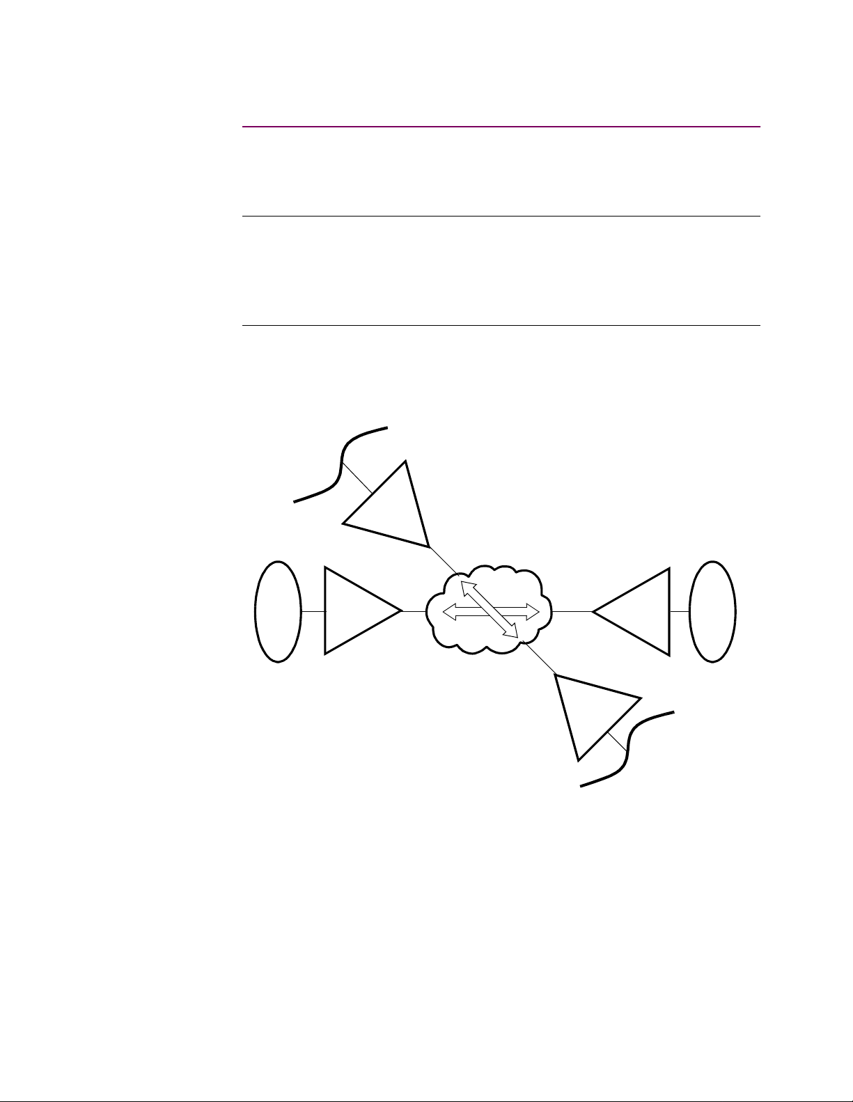
PathBuilder S200 series switches are intended for use in remote bridging solutions.
This means the PathBuilder S200 series sw itch is best used t o connect a re mote LAN
to the WAN to connect to other remot e LANs in you r networ k, as sh own in Fig ure 1.
Ethernet
PB S200
Token
Ring
PB S200
PB S200
X.25/FR
PB S200
Token
Ring
Ethernet
Figure 1. PathBuilder S200 Series Switch Bridge Combining Traffic
from Serial Devices
Figure 1 shows PathBuilder S200 series switches acting as remote bridges to
combine data traffic from Ethernet LANs to the WAN to connect to other remote
LANs in the network.
Bridging 1
Page 6

Mixed LAN Support PathBuilder S200 series switches support mixed LAN bridging, meaning you can
configure an Ethernet interface in the same node. Refer to the “Mixed LAN
Bridging” section on page 8 for more details.
Translational
Bridging
PathBuilder S200 series switches can use the Translational Bridging feature to
bridge traffic between Ethernet Networks. Translational Bridging provides a
PathBuilder S200 series switch with the capability to bridge non-routable protocols.
For information about enabling and configuring Translational Bridging, refer to the
“Configuring Translational Bridging” section on page 37.
No Local Bridging As mentioned earlier, PathBuilder S200 series switches are not intended for use in
local bridging applications where one LAN is connected directly to another LAN. It
is not recommended you use PathBuilder S200 series switches to perform local
bridging.
Transparent
Bridging
Transparent Bridging (TB) is the method used by PathBuilder S200 series switches
to bridge Ethernet LAN traffic from one Ethernet LAN to another one across a
WAN.
Refer to Transparent Bridging for Ethernet LANs on page 48 for more details on
these bridging operations.
Supported T raffic The PathBuilder S200 series switch family supports many types of protocols for
bridging operations. Some of the supported protocols include:
•Async
•SDLC
• Bisync
• Transparent Polled Async
• HDLC
• X.25
• Frame Relay
• Burroughs Poll Select
• NCR Bisync
2 Bridging
Page 7

In This Manual Topic See Page
Bridging Features and Capabilities .............................................................. 5
Token Ring LAN ...................................................................................... 6
Ethernet LAN ........................................................................................... 8
Mixed LAN Bridging ............................................................................... 10
MAC Addressing ..................................................................................... 11
LLC2 Local Termination ................................................................. ......... 12
Autolearn for Local Termination .............................................................. 13
Filtering .................................................................................................... 14
Spanning Tree Protocol ............................................................................ 15
Dual Ethernet LANs ................................................................................. 16
Basic Remote Bridging Examples ................................................................ 17
Bridge Hardware Components in PathBuilder S200 Series Switches .......... 19
Setting Up WAN Operation for Bridging ..................................................... 20
Configuring the PathBuilder S200 Series Switch for Bridging Operation ... 22
Bridge Parameters .................................................................................... 23
Bridge Link Parameters ............................................................................ 27
LAN Connection Table ............................................................................ 32
Limiting Bridge Frame Sizes ................................................................... 36
Configuring Translational Bridging ......................................................... 38
Source Route Bridging for Token Ring LANs ............................................. 40
Bridge Frame Handling ............................................................................ 41
Source Route Bridging Operation ............................................................ 42
Configuring Source Route Bridging Operation ....................................... 45
Connecting a Station to a Server in Source Route Bridging .................... 47
Transparent Bridging for Ethernet LANs ..................................................... 53
Forwarder Database and Spanning Tree .................................................. 58
Using Filters ............................................................................................. 59
Transparent Bridge Configuration Parameters ......................................... 61
Bridge Filtering ............................................................................................ 62
MAC Address Filtering ............................................................................ 63
MAC Address Filtering Examples ........................................................... 67
Identifying Address Links for MAC Addressing ..................................... 72
MAC Wildcard Filtering .......................................................................... 73
Configuring the MAC Address Filter Table ............................................. 74
Protocol Filtering ..................................................................................... 78
Configuring the Protocol Filter Table ...................................................... 79
NetBIOS Name Filtering .......................................................................... 84
Configuring NetBIOS Name Filtering ..................................................... 86
NetBIOS Name Filtering Statistics .......................................................... 92
NetBIOS Packet Formats . ........................................................................ 93
Spanning Tree Protocol Entity (STPE) ......................................................... 94
STPE Parameter Setting Considerations ......................................... ......... 97
Spanning Tree Timers .............................................................................. 103
Bridge Forward Delay Timer ................................................................... 105
LLC2 Local Termination .............................................................................. 108
Configuring Local Termination ................................................................ 114
Deleting LT Configuration Records ......................................................... 121
Mixed LAN Operation ................................................................................. 122
Dual LAN Ethernet ....................................................................................... 125
LAN Server Subsystem ................................................................................ 128
Configuring the LSS Record .................................................................... 130
Bridging 3
T0008-16F Release 5.2M
Page 8

In This Notice
(continued)
Topic See Page
Bridge Statistics ............................................................................................ 132
Spanning Tree St atistics ........................................................................... 133
Detailed Bridge Link Statistics ................................................................ 135
Bridge Link Filter Summary .................................................................... 138
Transparent Bridge Forwarding Table Statistics ...................................... 140
Transparent Bridge Detailed Bridge Link St atistics ................................. 142
LAN Connection Statistics ....................................................................... 144
LLC2 LT Session Summary Statistics ...................................................... 149
LLC2 LT Detailed Session Statistics ........................................................ 151
Reset Statistics .......................................................................................... 155
4 Bridging
Page 9
Bridging Features and Capabilities
Bridging Features and Capabilities
Introduction This section describes bridging features and capabilities of PathBuilder S200 series
switches.
Bridging Primer As mentioned earlier, Bridging extends the size and coverage of a Local Area
Network (LAN). PathBuilder S200 series switches provide bridging support for up
to two 802.3 (Ethernet) LAN interfaces per node or one 802.5 (Token Ring) LAN
interface) per node, and up to 32 remote bridge connections.
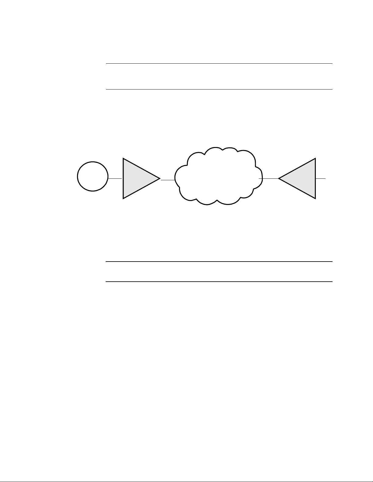
A PathBuilder S200 series switch b ridge can be connected t o a WAN backbone made
up of X.25, Frame Relay, or both, as shown in Figure 2.
Token
Ring
PB S200
FR/X.25
PB S200
Figure 2. Example of Typical PathBuilder S200 Series Switch Bridging
Application
PathBuilder S200 series switches are best suited for remote bridging operations
where traffic flows from one LAN through a WAN bridged by at least two
PathBuilder S200 series switches to another LAN.
Bridging 5
T0008-16F Release 5.2M
Page 10
Bridging Features and Capabilities
Ethernet LAN
What Is It? Ethernet is a common implementation of LAN topology wherein stations are
connected using a bus topology. Stations access the Ethernet using Carrier Sense
with Multiple Access and Collision Dete ction (CSMA/CD ).
PathBuilder S200
Series Switch
Support for
Ethernet
Example of Basic
Ethernet Frame
Format
PathBuilder S200 seri es switch Ethernet f unct io nal it y c omplies with the IEEE 802.3
specifications and provides Transparent Bridging to transport many different
protocols over the Wide Area Network (WAN) to remote destinations. Supported
protocols include:
• Novell Netware
•DECnet
• Banyan Vines
Figure 3 shows the basic frame formats for Ethernet frames supported by
PathBuilder S200 series switches.
Ethernet Frame Format
Preamble
8Octets
Destination Source Type
662445-1500
64-1518
Data
FCS
Figure 3. Frame Format for Ethernet Frames
802.3 MAC Frame
Figure 4 shows the supported 802.3 Ethernet MAC Frame format.
Format
802.3 MAC Frame Format
Preamble
SFD Destination Source Len Data Unit Pad FCS
DSAP SSAP Control Higher Layer Information
1 1 1 or 2
802.3.LLC
42-1497
Octets
Figure 4. 802.3 Ethernet MAC Frame Format Example
6 Bridging
Page 11

Bridging Features and Capabilities
Example of
Ethernet Bridge
Operation
Figure 5 shows an example of two Ethernet LANs connected across a WAN using
two PathBuilder S200 serie s switc hes as br idges . The ex ample sho ws a Frame Rel ay
WAN application, but you can also bridge across an X.25 WAN.
Frame Relay
PB S200PB S200
Figure 5. Ethernet Bridge Example
For More Details... For more details on bridging Ethernet LAN traffic, see Transparent Bridging for
Ethernet LANs on page 48.
Bridging 7
T0008-16F Release 5.2M
Page 12
Bridging Features and Capabilities
Mixed LAN Bridging
What is It? PathBuilder S24x, 26x, and 27x switches support a mixture of Token Ring and
Ethernet interfaces configured in the same node. This means the PathBuilder S24x,
26x, and 27x switch is able to perform remote Transparent bridging for Ethernet
LANs from the same PathBuilder S24 x, 26x, and 27x swit ch as shown in Fi gure 6. If
you happen to configure two Ether net LAN inter fa ces in the same node, instead of a
mix of one Ethernet and one Token Ring, you can perform local Transparent
bridging between the two Ethernet LANs.
Ethernet 1
Ethernet 2
Port 13
Port 19
PB S200
WAN
PB S200
Ethernet 1
Ethernet 2
Figure 6. Example of Mixed LAN Bridging in PathBuilder S24x, 26x, and
27x Switch
Note
Mixed LAN operation does not support translational bridging, meaning you
cannot pass LAN traffic from an Ethernet LAN to a Token Ring LAN without
using some sort of conversion software.
For More Details Refer to the “Mixed LAN Operation” section on page 114 for more details.
8 Bridging
Page 13

Bridging Features and Capabilities
MAC Addressing
What Is It? Bridges, whether they using Transparent Bridging, operate at the Data Link Layer,
which is concerned with MAC addressing. The MAC Address is a 6-byte MAC
(Media Access Control) address that identifies stations on a LAN. The IEEE
administers distribution of the MAC address to ensure no duplicates occur in MAC
addressing. This is accomplished by assigning a unique MAC address to each
manufacturer. Each manufacturer then assigns sequential values to the lower three
bytes for each interface manufactured.
For More Details For more details on MAC Address filtering, see the section “MAC Address
Filtering” section on page 58”in this manual.
Bridging 9
T0008-16F Release 5.2M
Page 14
Bridging Features and Capabilities
LLC2 Local Termination
LLC2 Local
Termination
PathBuilder S200 series switch support includes LLC2 Local Termination for your
Bridging operations when pas sing SNA/SDLC data tra f fic. LLC2 Local Termination
lets specific Token Ring ports generate and respond to LLC2 polls with local
acknowledgments, thereby preserving bandwidth and preventing session timeouts.
Local Termination, also referred to as “spoofing,” provides an efficient means for
carrying out an LLC2 session between two SNA end stations attached to separate
Token Ring LANs connected by a Wide Area Network (WAN).
Additionally, Local Termination provides detailed statistics on LLC2 sessions.
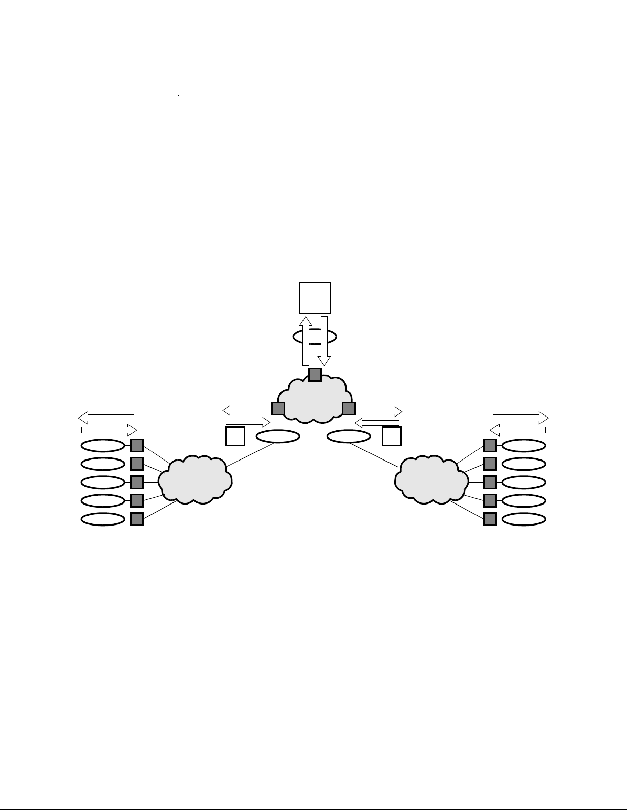
LT Example Figure 7 shows a network where running LLC2 Local Termination at the edge point
PathBuilder S200 series switches enables spoofing from one side of the network to
the other across multiple Token Rings.
SNA
FEP
LLC2
Keepalives/Acks
Keepalives/Acks
Keepalives/Acks
LLC2
LLC2
LLC2
Keepalives/Acks
LLC2
Keepalives/Acks
CC
CC
Figure 7. Local Termination Example
For More Details... See“LLC2 Local Termination” section on page 100 in this guide.
10 Bridging
Page 15
Bridging Features and Capabilities
Autolearn for Local T ermination
What Is It? Local Termination Autolearn reduces the amount of configura tion you need to do by
letting you spoof remote sessions without configuring a MAC address and a Service
Access Point (SAP) for each station running a session to the host Front End
Processor (FEP).
Since Local Termination supports up to 256 sessions for the PathBuilder S24x, 26x,
and 27x switch, Local Termination Autolearn can save you consid erabl e time duri ng
the configuration process.
Local Termination Autolearn is a default feature with PathBuilder S200 series
switches operating software meaning it requires no special configuration, other than
configuring the remote host MAC address in the PathBuilder S200 series switch
Local Termination (LT) Station tables.
It does not interfere with previously configured Local Termination spoofing
sessions.
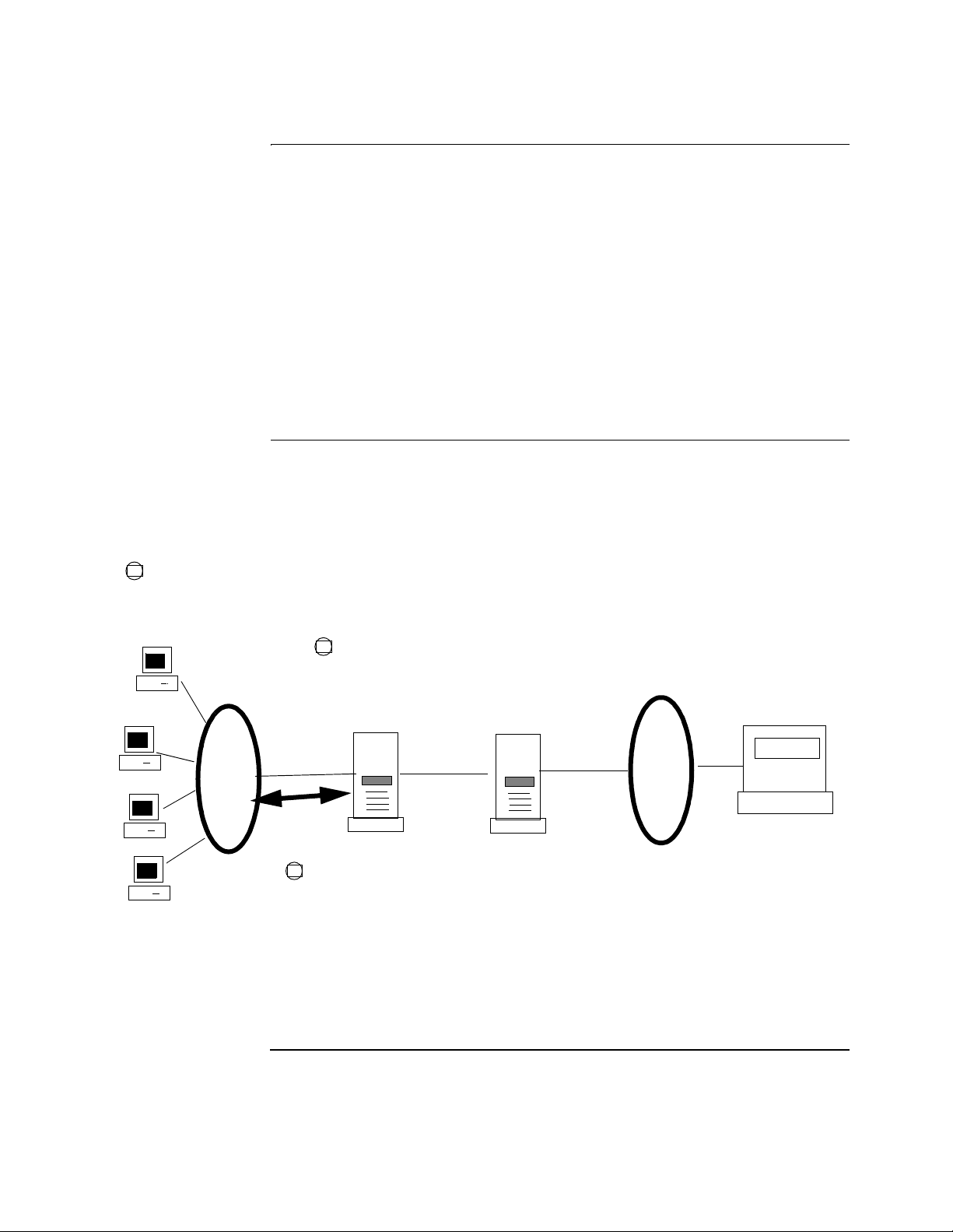
Example Figure 8 shows how a PathBuilder S200 series switch automatically learns the
address of PCs connected to the local bridge so you can pass data traffic to the host
without configuring entries in the Local Termination Station table for each PC
session.
1
The PC’s destination MAC address must match the
MAC address configured in the remote Host FEP for
local PB S200 to automatically learn LAN MAC
addresses.
Configure the Host FEP MAC address and SAP in the
2
LT station tables of the local an d remote bridges.
PB S200 automatically learns MAC addresses of any
LAN devices with matching desti na ti on MAC
addresses.
The local PB S200 running Local
3
Termination Autolear n automatically
learns MAC addresses of stations on
Destination MAC
addresses set up
40:00:00:00:10:88
local LAN.
Figure 8. Example of Local Termination Autolearn
PB S200
PB S200
Host MAC
address:
40:00:00;00:10:88
FEP
Bridging 11
T0008-16F Release 5.2M
Page 16

Bridging Features and Capabilities
Filtering
What Is It? Filtering lets you restrict data traffic from certain segments of your network. There
are different methods used to filter data traffic on a bridged network. PathBuilder
S200 series switch support for filtering includes:
• MAC Address Filtering
• NetBIOS Name Filtering
• Protocol Filtering
Mac Address
Filtering
NetBIOS Name
Filtering
MAC Addressing is important in a bridging operation because one of the most
common tasks in a bridging environment is to provide filtering of data frames.
Filtering provides a way of stopping certain d evi ce s f rom c ommunicating with other
devices in a network. One way to filter traffic through a bridge is by identifying the
devices you want to block by their MAC Addresses.
For more details on MAC Address filtering, see the section “MAC Address
Filtering” section on page 58” in this manual.
The NetBIO S Name Filtering feature of PathBuilder S200 serie s switches le ts you
restrict or filter all NetBIOS broadcasts, except those to or from a list of servers.
NetBIOS Name Filtering compares NetBIOS broadcasts to a “pattern” that may have
a wild card “*” character at the end. For example, if all servers have a naming
convention with the fir st pa rt of t he name the same, for example, “SVR...”, then you
can complete only one ent ry i n t he Ne tBIOS Filter Table to permit broadcasts to and
from the “SVR*” name pattern.
With NetBIOS Name Filters, you can block the local service name (for example,
“SNA_GW”) on the WAN link so that NetBIOS broadcasts to and from that name
are not forwarded across to the internetwork.This feature lets the branches use the
same name for their loc al SNA ser vi ce a nd you can configure all th e workstations to
access the same local SNA name.
Refer to “NetBIOS Name Filtering” section on page 76 in this guide.
Protocol Filtering Protocol filtering prevents nodes operating with a certain protocol from operating
outside their intended scope.
Refer to the“Protocol Filtering” section on pag e 70 for more details.
12 Bridging
Page 17

Bridging Features and Capabilities
Spanning T ree Protocol
What Is It? Spanning Tree Protocol reduces multiple bridge paths between LANs to a single
path. Instead of a mesh network with several paths to a destination, the Spanning
Tree Protocol remaps the network so that only one path is active for traffic between
any source station and any destination station. The other paths block any frames
between the LANs.
A spanning tree network eliminates parallel paths and traffic loops.
The PathBuilder S200 series switch implementation of the Spanning Tree Protocol
Entity (SPTE) conforms to IEEE 802.ID specifications. Refer to the IEEE 802.ID
specification for more detailed information on Spanning Tree Protocol operation.
Automatic &
Manual Spanning
Tree Support
PathBuilder S200 series switch support both automatic and manual spanning tree
operations.
If you do not want to configure spanning tree operation yourself, you can use the
automatic spanning tree creation option. Remember that a all bridges in your
network must be configured to automatic spanning tree operation to allow for the
spanning tree protocol to determine the spanning tree.
For More Details... See the“Spanning Tree Protocol Entity (STPE)” section on page 86.
Bridging 13
T0008-16F Release 5.2M
Page 18

Bridging Features and Capabilities
Dual Ethernet LANs
What Is It? The PathBuilder S24x, 26x, and 27x switch supp orts up to two Ethernet LANs in t he
same node. This means you can connect up to two Ethernet LANs to a single
PathBuilder S24x, 26x, and 27x switch to perform bridging and routing of LAN
traffic across the WAN to multiple Ethernet LANs. Before Dual Ethernet LAN, the
PathBuilder S24x, 26x, and 27x switch supported only one Ethernet LAN port for
remote bridging and routing of LAN traffic.
For More Details... See the “Dual LAN Ethernet” section on page 117.
14 Bridging
Page 19
Basic Remote Bridging Examples
Basic Remote Bridging Examples
Introduction This section shows some common examples of bridging applications using
PathBuilder S200 series switches.
Remote Bridging
Across a WAN
Extended Bridging
for Multiple LANs
Figure 9 shows a common Source Route Bridging operation for PathBuilder S200
series switches where two Token Ring LANs are attached across a WAN. For
example, two LANs could be bridged using two PathBuilder S200 series switches
interconnected by an X.25 or Frame Relay link. Bridged traffic flows between the
bridges over a Swit ched Virtual Circuit (SVC) tha t conne cts them t ogether a cross th e
WAN (or Permanent Virtual Circuit (PVC) for Frame Relay).
Token
Ring 1
PBS200
Node 1
X.25/Frame Relay
PBS200
Node 2
Token
Ring 2
Figure 9. PB S200s Connecting LANs via an X.25/Frame Relay Link
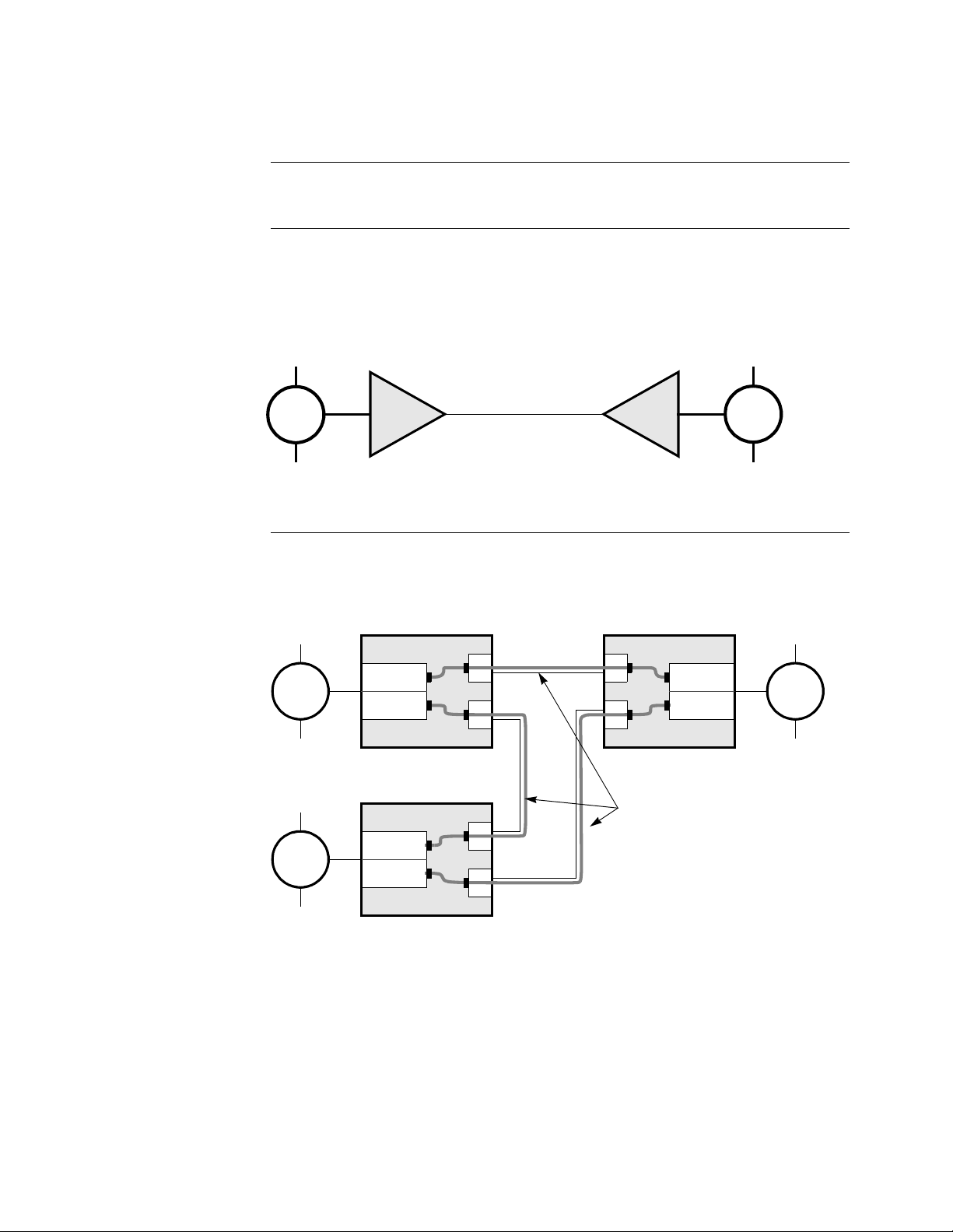
If more than two remote LANs are involved in your bridging application, the bridge
arrangement can be e xtended s o that individua l LAN pair s are co nnected by di ff erent
bridges, as shown in Figure 10.
Token
Ring 1
Node 1
Bridge 1
Bridge 2
Node 2
Bridge 1
Bridge 3
Token
Ring 2
Token
Ring 3
Node 3
Bridge 2
Bridge 3
SVC Connectors
(PVC for Frame Relay)
Figure 10. Two-Port Bridges Connecti ng Mult ipl e Token Ring LANs
In this example, each pair of LANs is connect ed by a sing le bridge fo rmed by bridge
pairs.
• Bridge 1 interconnects Token Ring 1 and Token Ring 2
• Bridge 2 interconnects Token Ring 1 and Token Ring 3
• Bridge 3 interconnects Token Ring 2 and Token Ring 3
Bridging 15
T0008-16F Release 5.2M
Page 20
Basic Remote Bridging Examples
A Less Complex
Extended Bridge
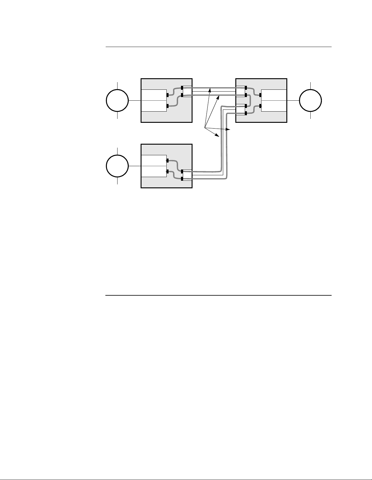
Figure 11 shows a possible arrangement of SVCs (PVCs for Frame Relay) that
produces the same bridge arrangement as shown in Figure 10.
Token
Ring 1
Token
Ring 3
Node 1
Bridge 1
Bridge 2
SVC Connectors
Node 3
Bridge 2
Bridge 3
Node 2
Bridge 1
Bridge 3
Token
Ring 2
Figure 11. Example of Bridges in an SVC Arrangement
In this arrangement, all LAN segments are one hop away from each other since they
are directly attached by a single pair of bridges. In Figure 11, Token Ring 1 is one
bridge away from Token Ring 2 and Tok en Ring 3 and the same applies for the othe r
rings.
From a bridged netw or k po int of view, Token Ri ng 1 i s one bridge away fr om Token
Ring 3, but Node 1 is not directly connected to Node 3. Traffic between Token Ring
1 and T oke n Ring 3 does n ot have to pass th rough Token Ring 2. This is an important
advantage in configuring bridge networks with the PathBuilder S200 series switch
because you can form a minimal bridge network to accomplish the desired
interconnectivity.
16 Bridging
Page 21
Bridge Hardware Components in PathBuilder S200 Series Switches
Bridge Hardware Components in PathBuilder S200 Series Switches
Introduction This section describes bridge hardware configuration and connections for the
PathBuilder S200 series switch.
Bridge
Configuration and
Connections
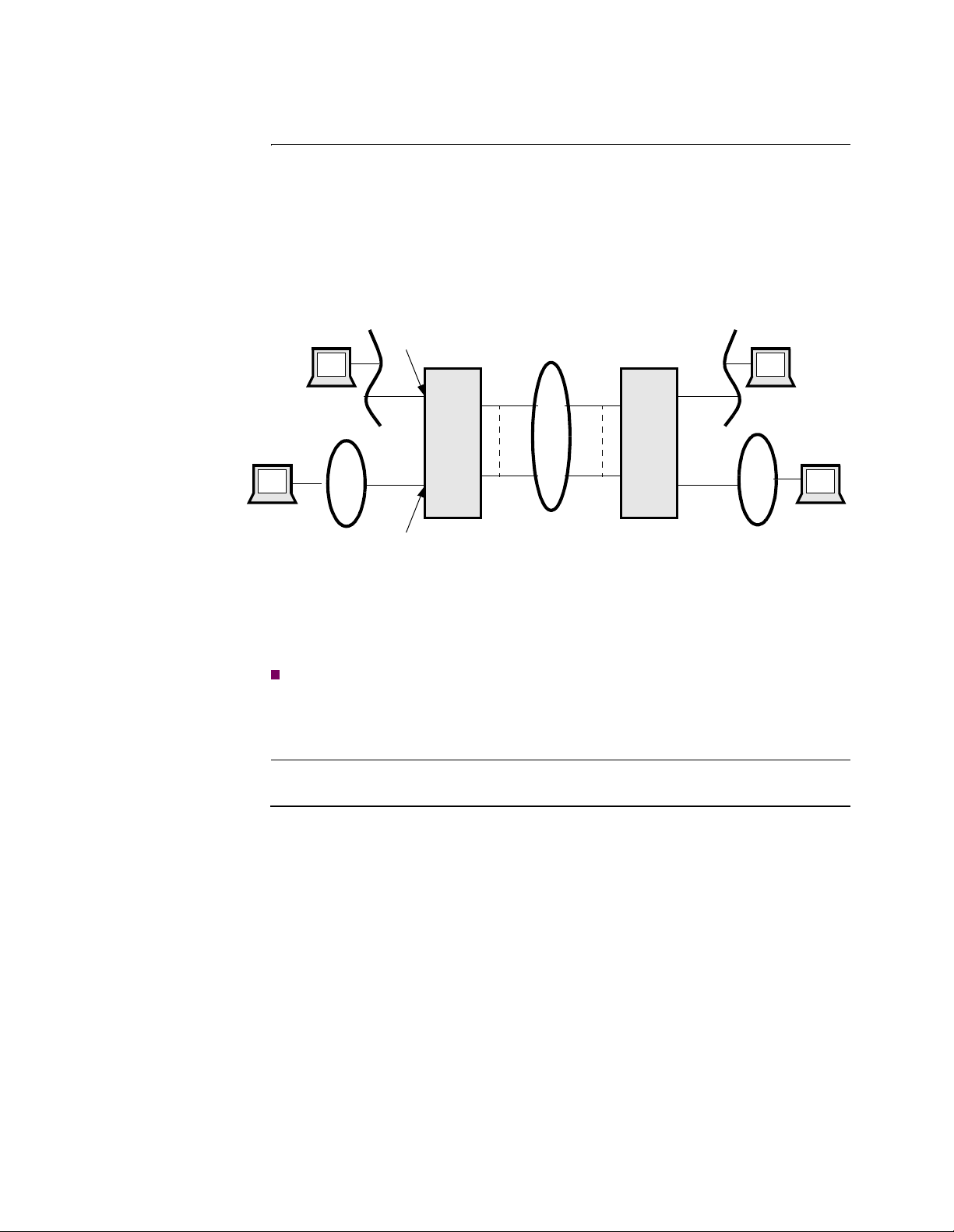
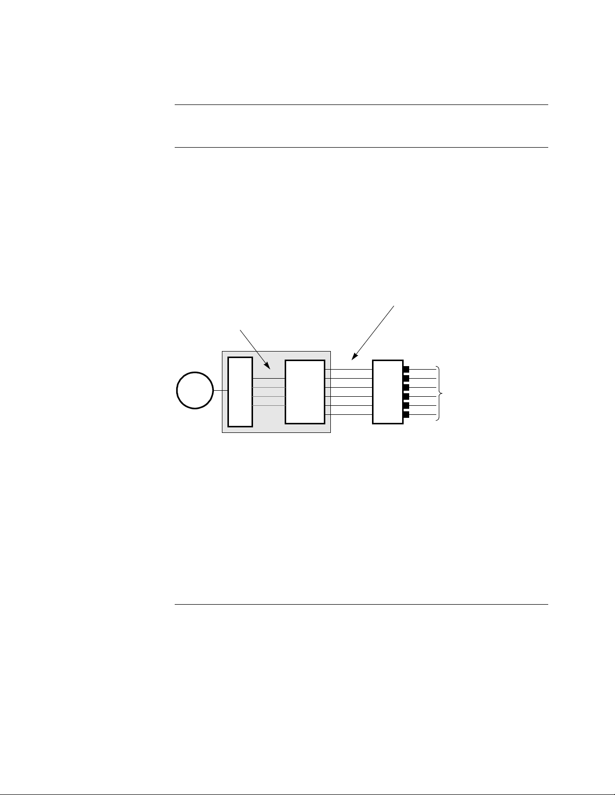
Figure 12 shows the physical connections of the modules that provide bridging
functiona lity for PathBuilder S200 series switch . This figure shows a LAN port
module and supporting WAN Adapter module within a PathBuilder S200 series
switch. The LAN port module is br oken out int o a driver and a forwarder to show the
concept of bridge links.
At each end node, the bridge has connectio ns referr ed to as brid ge links. Bridge links
that connect to the LAN are referred to as LAN bridge links. Bridge links that
connect to remote bridges across the WAN are referred to as WAN bridge links.
LAN Link Numbers range from 1 to
4: up to two LAN connections are
supported for Ethernet.
LAN Port Module
Token
Ring
LAN
LAN
Driver
1
Forwarder
LAN
Bridge
5
.
.
.
.
32
Up to 32 WAN links can be defined
(numbered 5 to 36), o ne f or each
bridge connection over an SVC
(PVC for Frame Relay).
WAN
Adaptor
X.25 SVCs connected to
SVCs on network ports
(PVCs for Frame Relay)
Figure 12. LAN Port Module and WAN Adapter Module (Logical View)
The LAN port consists of low level drivers and the bridge forwarder. This can be
viewed as the functioning bridge. The WAN Adapter is closely associated with the
bridge. The WAN Adapter provides the network services that the bridge requires in
order to function over the WAN network. The principal service is establishing and
maintaining S VC (PVC for Frame Relay) connections to remote LAN bridge
forwarders so that virtual circuits can be formed betwee n the forwarders.
The bridge sees the LAN and th e WAN (by means o f the WAN Adapter) as networ ks
it is attached to by links. There are a total of 36 links: four LAN links and 32 WAN
links.
LAN Interface
Support
The PathBuilder S200 series switch supports only one LAN per node, so only one
link is needed for the LAN port connection: link number 1. The PathBuilder S24x,
26x, and 27x switch supports up to two Ethernet LANs per node. See “Dual LAN
Ethernet” section on page 117 for more details on this functionality.
On the PathBuilder S200 series switch links numbered 2 to 4 are not used and are
reserved for future configurations. WAN links are numbered 5 to 36 and provide up
to 32 WAN connection links which correspond to potential bridges.
Bridging 17
T0008-16F Release 5.2M
Page 22

Bridge Hardware Components in PathBuilder S200 Series Switches
18 Bridging
Page 23
Setting Up WAN Operation for Bridging
Setting Up W AN Operation for Bridging
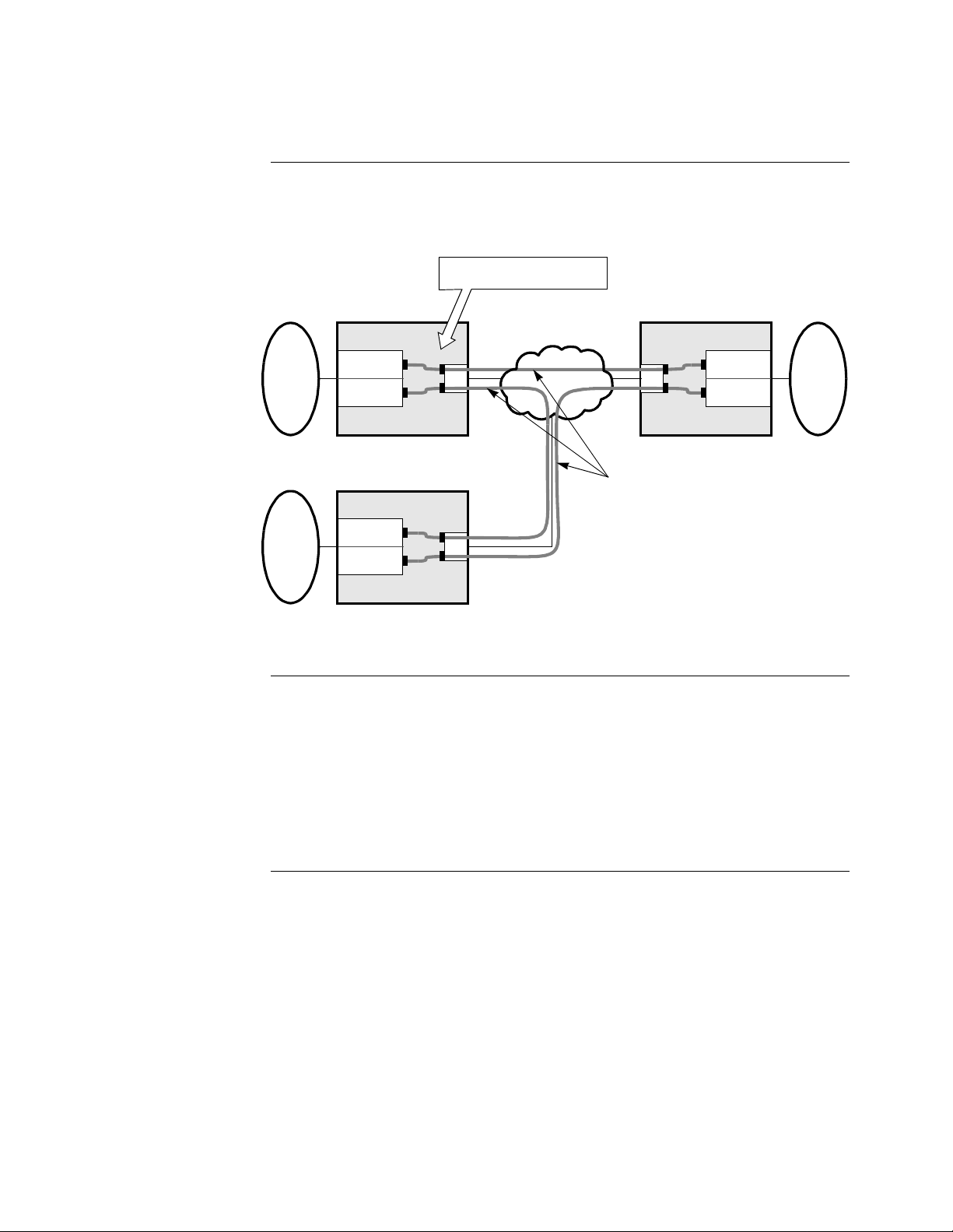
Introduction With the 3Com Bridging Protocol option, you can use PathBuilder S200 series
switches to connect remot e LANs a cr oss a Wide Area Network (WAN), as shown in
Figure 13.
Codex Proprietary Protoc ol ID
LAN Connection Subaddress
Critical Parameter s
for WAN Operation
LAN
AAA
LAN
DDD
Node 1
Bridge 1
Half
Bridge 2
Half
Node 3
Bridge 2
Half
Bridge 3
Half
WAN
SVC Connectors
Node 2
Bridge 1
Bridge 3
Half
Half
LAN
CCC
Figure 13. Interface Connections Between WAN and LAN
Before you can use a PathBuilder S200 series switch as a bridge to connect LANs
over a WAN, you must configure the following two parameters in the Node record
for the bridge node. In most cases, use default values:
• Codex Proprietary Protocol ID
• LAN Connection Subaddress
You also need to configure the LAN Connection Table. Entries in this table are for
the WAN Adapter and specify co nnections going acr oss a wid e area ne twork, such as
X.25, Frame Relay, or other proprietary protocols.
Codex Proprietary
Protocol ID
The Protocol Identi fi er (ID) is placed o n t he Call User Data fie ld of t he Call Request
packet. This packet is generated by the Autocall used to establish a circuit for a
bridge link. If the bridge link is not configured to initiate an autocall, then this
configured value is ma tched with that found in an In coming Call pa cket to det ermine
if the call should be established.
To define the Codex Proprietary Protocol ID, select a value within the designated
range. Normally you would not configure a value different from the default value.
The only reason to use a different value is if the default value conflicts with one
already in use.
It is recommended that the Protocol ID value in all network nodes be the same.
Bridging 19
T0008-16F Release 5.2M
Page 24

Setting Up WAN Operation for Bridging
LAN Connection
Subaddress
The LAN Connection Subaddresses identifies all LAN Connections. Incoming calls
with a network address consisting of the Node Address specified in the Node record
and the LAN Connection Subaddress, specified in the LAN Connection Table, are
verified and allowed to connect to the WAN Adapter in order to reach the LAN
bridges.
The LAN Connection Subaddress is appended to the calling address of the Call
Request packet if generated and sent by the WAN Adapter. Use the default value
unless it conflicts with an address already in use.
Refer to the “LAN Connection Table” section on page 31 for more details.
20 Bridging
Page 25

Configuring the PathBuilder S200 Series Switch for Bridging Operation
Configuring the PathBuilder S200 Series Switch for Bridging
Operation
Introduction This section shows you how to configure a PathBuilder S200 series switch for
bridging operation.
What You Need to
Configure
When you are performing a Transparent Bridging operation, configure the following
records in the bridge node:
•Node Record
• LAN Port Record
•Bridge Record
• Bridge Link Record
• LAN Connection Table
• Optional Filter Tables
• LAN Server Subsystem (LSS) Record (optional)
• Autocall Mnemonic Table (Some of the WAN Adapter connections are
configured to Autocall.)
• Routing Table (At the destination node, a LAN Connection [LCON] entry is
needed for the WAN Adapter.)
For general details on configuring the Node record and the LAN Port record, refer to
the PathBuilder S200 Series Basics Protocols. For details on LAN Server Subsystem
configuration, see the “LAN Server Subsystem” section on page 120.
The following sections describe how to configure the records and tables critical for
performing bridging on a PathBuilder S200 series switch.
Bridging 21
T0008-16F Release 5.2M
Page 26
Configuring the PathBuilder S200 Series Switch for Bridging Operation
Bridge Parameters
Bridge Port Record
Parameters
After you configure the Node record and the LAN Port record for the bridge node,
configure the Bridge parameters. Figure 14 shows the parameters that make up the
Bridge Parameters record.
Node: Address: Date: Time:
Menu: Configure Bridge Path:
Bridge Parameters
*Max Number of Bridge Links
*STPE Control
Bad Hello Threshold
Bad Hello Timeout
Learn Only Period
Aging Period
Bridge WAN Data Priority
Bridged Protocols
Local Bridge ID
Figure 14. Configure Bridge Parameters
Parameters These parameters make up the Bridge Parameter Record.
*Maximum Number of Bridge Links
Range: 36 to 250
Default: 36
Description: Specifies the maximum number of bridge links allowed.
Boot Type: A change to this parameter requires a Node boot to take effect.
22 Bridging
Page 27

Configuring the PathBuilder S200 Series Switch for Bridging Operation
*STPE Control
Range: AUTO, MAN
Default: MAN
Description: The Spanning Tree Protocol Entity (STPE) module in the Path-
Builder S200 series switch provides automatic calculation of the
spanning tree. Spanning tr ee all ows f or the prop er support of single
route broadcast frames that occur in LANs. This parameter controls
how a bridge determines the Spanning Tree: either automatically
using the STPE, or manually using additional parameters in the
bridge link record.
• AUTO: The bridge participates in Spanning Tree Protocol
(STP) and automatically determines the single path between
LANs using the “Path Costs” assigned to the different links.
Bridge protocol data units (BPDUs) are special frames used to
continually communicate this information between bridges.
• MAN: The Spanning Tree is configured by the network
administrator. This is done using the STPE Link State
parameter found in the next section, “Bridge Link Parameters.”
Configure all bridges in your network to MANual if you are not an
expert user of Spanning Tree protocol operation. This prevents
problems in operation, especially when lower speed WAN links are
involved in forming bridges.
Note
If STPE Control parameter is set to MAN, the following parameter appears.
Bad Hello Threshold
Range: 10 to 30
Default: 15
Description: Use this parameter to generate alarms when some bridges are
configured AUTO and others are configured MAN in order to
detect nonmatching configurations.
A Bad Hello counter is incremented when a HELLO Protocol Data
Unit (PDU) is received while the STPE Control parameter is
configured to MAN. An event (alarm) is generated when the
counter exceeds the value of this parameter. The event is generated
only once during the Bad Hello Time.
Note
If STPE Control parameter is set to MAN, the following parameter appears.
Bad Hello Timeout
Range: 10 to 30
Default: 15
Bridging 23
T0008-16F Release 5.2M
Page 28

Configuring the PathBuilder S200 Series Switch for Bridging Operation
Bad Hello Timeout
(continued)
Description: Represents the timeout value in minu tes. Th e Bad Hel lo coun te r is
reset when the timeout expires and can be used to control how
frequently the Hello counter reaches its alarm threshold.
Learn Only Period (used for Ethernet only)
Range: 2 to 604800
Default: 10
Description: The time in seconds that a bridge is prevented from forwarding
frames after the forwarding is cleared due to a node boot.
Aging Period (used for Ethernet only)
Range: 2 to 1000000
Default: 10
Description: Specify the time in seconds that a learned entry in the Forwarding
Table is allowed to remain in the table without being updated
(relearned). If t he e ntry is not updat ed within this time period, it is
discarded from the table.
Bridge WAN Data Pri o rity (used for Ethernet only)
Range: EXP, HIGH, MED, LOW
Default: HIGH
Description: Specify the transmission priority of the bridged data over the
WAN.
24 Bridging
Page 29

Configuring the PathBuilder S200 Series Switch for Bridging Operation
Note
If STPE Control parameter value is AUTO, this parameter appears.
Bridged Protocols
Range: None, IP, IPX
Default: None
Description: Specify the routable protocols that can be bridged across BROUT
or BRID links. “None” specifies no routable protocols (IP, IPX)
will be bridged. “IP” specifies that IP packets can be bridged.
“IPX” specifies that IPX packets can be bridged.
Note
Any combination of the available selections may be specified by
summing, such as IP + IPX.
Bridging 25
T0008-16F Release 5.2M
Page 30

Configuring the PathBuilder S200 Series Switch for Bridging Operation
Bridge Link Parameters
Introduction The bridge uses Bridge Li nks as connections to the LAN and WAN networks.
The LAN Bridge Link connects the bridge directly to the local LAN, and its
parameters control the characteristics of this connection.
The WAN Bridge Link parameters let you establish and maintain SVC connections
to a remote LAN bridge. The bridge views the LAN bridge links and the WAN
bridge links as links to the network s attached to it.
Bridge Link
Parameters
Figure 15 shows the Bridge Lin k parameters.
Node: Address: Date: Time:
Menu: Configure Bridge Path:
Bridge Parameters
Bridge Link Parameters
Entry Number
Bridge Type
Bridge ID
Hop Count Limit
Largest Frame Size
MAC Address Filter Action
Protocol Filter Action
NETBIOS Name Filter Action
STPE Link State
Link Mode
Virtual Ring Number
Figure 15. Configure Bridge Link Menu
26 Bridging
Page 31

Configuring the PathBuilder S200 Series Switch for Bridging Operation
Parameters These parameters make up the Bridge Link Record.
Entry Number
Range: 1, 5 to 36
Default: 1
Description: Specify the Bridge Link number that references this record. Two
Ethernet LANs can be configured on the PathBuilder S24x, 26x, and
27x switch using 1 and 2. Links 1-4 are reserved for LAN port
connections.
There are 32 possible WAN Bridge Links, numbered 5 to 36. Bri dges
are formed by PVC/SVC connec tions to WAN bridge li nks in r emote
PathBuilder S200 series switch. Each bridge link used in a WAN
connection is connected to a remote bridge link and such an arrangement forms a bridge between the two LANs.
At the destination node, th e routing t able must have an entry tha t lists
the destination por t as LCON (LAN Connect ion). This al lows the cal l
to be directed to a connection on the WAN Adapter.
Note
The following parameter appears if you enter 5 top 36 at the Entry Number
parameter.
Bridge_Type
Range: SR, TB, BOTH_SR_AND_TB
Default: TB
Description: This is the bridge type for links connect ing to WANs. It defines the
kind of bridging that will be employed on the link. It applies only
to WAN links, number 5 to 36, the maximum number of links
allowed.
Choose:
• TB - to perform Transparent Bridging
• BOTH_SR_AND_TB - when you perform mixed LAN
bridging operation. This lets the node perform TB and SRB
operations simultaneo usl y.
Bridge ID
Range: 0 to 15
Default: 1
Description: A bridge number uniquely id ent if ie s a b ri dge when mor e t han one
bridge is used to span the same two segments. This should match
the Bridge ID of the remote Bridge half.
Bridging 27
T0008-16F Release 5.2M
Page 32

Configuring the PathBuilder S200 Series Switch for Bridging Operation
Hop Count Limit
Range: 0 to 7
Default: 7
Description: Specifies the maximum number of bridges through which a
broadcast frame may pass on the way to its destination.
Largest Frame Size
Range: 516, 1500, 2052, 4472
Default: 2052
Description: Specifies the maximum size of the INFO field that this Bridge
Link can send and receive. The minimum value of this parameter
or of adjacent Bridge Li nk or values of Largest Frame Size of
bridge wide parameter is used to determine whether a modification
of the Routing Control field of RIF is necessary.
MAC Address Filter Action
Range: NONE, PASS, BLOCK
Default: NONE
Description: Specify how the MAC Address Filter Table is used.
• NONE: No MAC address filtering using the MAC Address
Filter Table is performed for this link.
• PASS: Look in the MA C Address Filter Table for an entry
with a matching MAC frame address and take the filtering
action specified by this filter table. If no matching entry is
found, this value indicates that this frame should be passed.
• BLOCK: Look in the MAC Address Filter Table for an entry
with a matching MAC frame address and take the filtering
action specified by this filter table. If no matching entry is
found, this value indicates that this frame should be blocked.
28 Bridging
Page 33

Configuring the PathBuilder S200 Series Switch for Bridging Operation
Protocol Filter Action
Range: NONE, PASS, BLOCK
Default: NONE
Description: Functions similarly to the MAC Address Filtering Action
parameter. The filtering is applied to each lin k. Fr ames pass in g on
a link can be either incoming or outgoing.
• NONE: No Protocol fi ltering using t he Proto col Filter Table is
to be performed for this link.
• PASS: Look in the Protocol Filter Table for an entry with a
matching frame address and take the filter in g action specified
by this filter table. If no ma tching entry is found, this value
indicates that this frame should be passed.
• BLOCK: Look in the Protocol Fil te r Table for an entry with a
matching frame address and take the filter in g action specified
by this filter table. If no matching entry is found, this value
indicates that this frame should be blocked.
NETBIOS Name Filter Action
Range: PASS, BLOCK, NONE
Default: NONE
Description: Specify how NetBIOS Name Filter is used on this node:
• PASS: Pass all frames with NETBIOS name not listed in
NETBIOS Name Filter Table.
• BLOCK: Block all frames with NETBIOS name not listed in
NETBIOS Name Filter Table.
• NONE: No NETBIOS name filtering to be perf ormed for t his
link.
STPE Link State
Range: FORWARD, BLOCK
Default: FORWARD
Description: Specify whether to forward or block data frames when the STPE
Control parameter is configured to MAN.
Bridging 29
T0008-16F Release 5.2M
Page 34

Configuring the PathBuilder S200 Series Switch for Bridging Operation
Link Mode
Range: NORMAL,RFC1294, TRANS
Default: NORMAL
Description: Specify one of the following:
• NORMAL - Bridge link connects to another Bridge using the
Link Control Protocol to determine remote Ring Number.
This option is not supported for PVC connections. Use
another option for PVC connections.
• RFC1294- Bridge link uses RFC1294 (or RFC1490) bridging
to connect to another Bridge or Frame Relay Access Device.
A Bridge Link Virtual Ring Number is required
• TRANS - Translational Bridging support for PathBuilder
S24x, 26x, and 27x switch only.
Boot Type: A change to this parameter requires a node boot to take effect.
Note
The following parameter appears if you set Link Mode to RFC1294
Virtual Ring Number
Range: 0001-0FFF hexadecimal
Default: 0000
Description: This is a virtual ring number that is used by the Bridge Link for
connecting to another Bridge or Frame Relay Access Device via
RFC1294 or RFC1490 Bridging. It must match the virtual ring
number of the connecting Bridge or Frame Relay Access Device.
30 Bridging
Page 35

Configuring the PathBuilder S200 Series Switch for Bridging Operation
LAN Connection Table
Introduction The LAN Connection Table provides information about the connections that cross
over the WAN.
LAN Connection
Table Parameters
Figure 16 shows the LAN Connection Table parameters.
Node: Address: Date: Time:
Menu: Configure Path:
Node
Port
:
:
:
LAN Connection Table
Entry Number
*LAN Forwarder Type
LAN Connection Type
Router Interface Number
Encapsulation Type
Autocall Mnemonic
LCON Queue Limit
Billing Records
Traffic Priority
Figure 16. LAN Connection Table Menu
Parameters These parameters make up the LAN Connection Table Record.
Entry Number
Range: 1 to 32
Default: 1
Description: Specify the entry number used to reference this table record.
Bridging 31
T0008-16F Release 5.2M
Page 36

Configuring the PathBuilder S200 Series Switch for Bridging Operation
*LAN Forwarder Type
Range: ROUT, BRID, BROUT
Default: ROUT
Description: Specify if the LAN Connection is to pass bridged, routed, and/or
brouted traffic:
• BRID: Bridged LAN traffic is transported across this
connection.
• ROUT: Routed LAN traffic is transported across this
connection.
• BROUT: Both bridge d and route d LAN tr af fic are trans porte d
across this connection.
Boot Type: Changes to this parameter require a Node Boot to take effect.
LAN Connection Type
Range: PT_to_PT, GROUP
Default: PT_to_PT (Point-to-Point)
Description: Specify whether this LAN Connection defines a point-to-point
connection across the WAN, or is part of a group of LAN
Connections. If configur ed as GROUP, multiple LAN Connections
can use the same Router Interface number. If configured as
PT_to_PT, the Router Interface configured must be unique to this
LAN Connection.
Note
This parameter appears if the LAN Forwarder Type is configured
as ROUT or BROUT.
Boot Type: When changing from GROUP to PT_PT, a Node boot is required.
Otherwise, a Table and Node Record boot is required.
Router Interface Number
Range: 5 to n, where n = 36 to 254
Default: 5
Description: Specifies a Router Interface using this LAN Connection record.
This connection makes it possible to pass LAN data through the
WAN network to a remote router. The allowable range of values
reflect the maximum number of IP or IPX interfaces set in the IP
or IPX Parameters Menu.
Note
This parameter appears if the LAN Forwarder Type is configured
as ROUT or BROUT.
Boot Type: Changes to this parameter require a Node Boot to take effect.
32 Bridging
Page 37

Configuring the PathBuilder S200 Series Switch for Bridging Operation
Encapsulation Type
Range: RFC 877, RFC 1294
Default: CODEX
Description: Specify the type of encapsulation used over this LAN connection.
Encapsulation types supported include:
• CODEX: Codex Proprietary Encapsulation
• RFC 877/1356: RFC 877/1356 X.25 protocol encapsulation
for IP
• RFC 1294/1490: RFC 1 294/1490 mul tiprotocol encapsul ation
over Frame Relay
Boot Type: Changes to this parameter require a Table and Node Record boot
to take effect.
Autocall Mnemonic
Range: 0 to 8 alphanumeric characters
Default: 0 (blank)
Description: Specify the mnemonic name used when the LAN connection is
configured to autocalli ng. A cor re spon ding entry must be made in
the Mnemonic Table. A blank entry means autocalling will not be
initiated by this LAN connect ion entry. The LAN connector at the
remote device must initiate the call. If configured, the Autocall
Mnemonic references a remote address which will be called by the
LAN connection.
Specifically, it must equal the node address of the node to which
the remote LAN is attached (the LAN to which we want to
bridge). The LAN connection subaddress configured in the node
record is appended to this address to form the complete ca lled
address of an X.25 call.
LCON Queue Limit
Range: 0 to 65536
Default: 16000
Description: The LCON Queue Limit parameter specifies the maximum
number of bytes that are queued for this LAN before transmission
on the WAN link. Set this par ameter fo r two sec onds of da ta on th e
WAN link.
Bridging 33
T0008-16F Release 5.2M
Page 38

Configuring the PathBuilder S200 Series Switch for Bridging Operation
Billing Records
Range: OFF, ON
Default: OFF
Description: Enables or disables the creation (storing and printing) of billing
records for the LAN connection:
• ON: Billing records are generated.
• OFF: Billing records are not generated.
Traffic Priority
Range: LOW, MED, HIGH, EXP
Default: HIGH
Description: Specify the Tr affic Priority level of this LAN Connection.
• LOW: One Low Priority packet is sent for every Traffic
Priority Ste p number of Medium priority p ackets.
• MED: One Medium priority packet is sent for every Traffic
Priority Ste p number of Hig h priority pack ets.
• HIGH: High is the first level of priority packets sent, if no
expedite priority packets are sent.
• EXP: Expedite priority packets have the highest priority and
use all of the link bandwidth that they need. Any remaining
bandwidth is shared by the high, medium, and low priority
packets.
34 Bridging
Page 39

Configuring the PathBuilder S200 Series Switch for Bridging Operation
Limiting Bridge Frame Sizes
Overview Although there are valid reasons for using larger frame sizes on bridges, there are
limiting factors that must be considered when selecting a maximum frame size.
There are several reasons for limiting the maximum size of the frame, especially
where bridging is done remotely across a WAN:
• The larger the frame, the longer it takes to transmit the frame on a WAN link.
• Increasing the frame size also causes a reduction in frame overhead.
Conversely, the smaller the frame, the less time it takes to t ransmit the fr ame. Since a
smaller frame cannot be for war ded by an inte rmed iary node until it is fu lly rec eived,
a large fra me cannot be f orward ed fo r the time i t take s to t ransmit an d recei ve it over
a given link. On a LAN, this time is less of an issue where the link speed is
approximately 10 Mbps. On a WAN link, it becomes an issue because the
transmission times for large frames become significant.
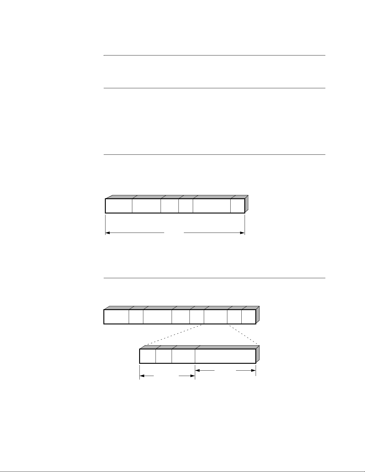
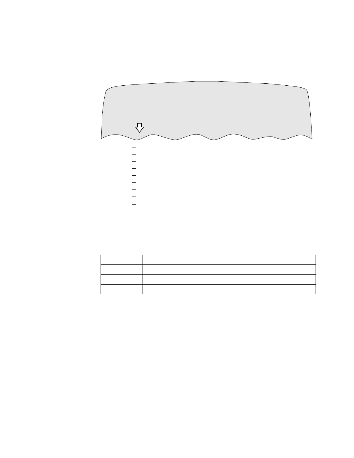
Example of Frame
Sizes
Figure 17 shows the effect on trans it de lay acr oss a n etwork f or two c ases: in one, a n
end system sends a large packet as a single frame and in the other, the same large
packet is sent as three smaller packets.
Large Packet
Total Transit
Tim e
Small Packet
Total Transit
Time
End
System
A
End
System
A
Node 1 Node 2 Node 3
Node 1 Node 2 Node 3
End
System
B
End
System
B
Figure 17. How Packet Size Affects Transit Delay
Small packets are forwar ded more quickl y by interme diate nodes resulting in the end
system receiving several short frames in less time than a long frame. How much
improvement is achieved depends on the transmission times and line speeds
involved. The trade-off in this case is that even though the transit delay is reduced,
the packet-per-second load is increased on all three nodes (and two end systems)
involved. In this case, the factor is at least three if continuous streams of packets are
involved.
Bridging 35
T0008-16F Release 5.2M
Page 40

Configuring the PathBuilder S200 Series Switch for Bridging Operation
Increasing the fra me size als o caus es the re ducti on in frame ove rh ead. If a 1000 byte
data packet required a 50 byte header (frame + IP + TCP), then if 2000 bytes were
placed in the frame with th e same frame, the di f fere nce in over hea d is 50/100 0 = 5%
versus 2.5%. As the size of the data increases, the overhead becomes even less.
However, a t th ese levels, the gain is marginal. Other factors ma y re duce thi s met hod
of gain considerably. For example, intermediate systems have a limit on how large a
frame they can handle.
As the size of the fr ame become s larger, there is a correspo nding i ncr ease i n the ti me
the frame spends in transmission media. The error rate of transmission media is finite
and becomes a pro blem when the ti me for tra nsmittin g a frame becomes l ong enough
that the probability of an e rror occurring during the transmission time is likely. An
error on a large frame with its subsequent retransmission means the media are used
with unproductive transmissions and reduced efficiency.
Standard Frame
Sizes
In general, these industry standards can be used as a guideline for selecting the
maximum frame size.
Max Frame Size Line Speed Range (kbps)
512 9.6 to 38.4
1500 38.4 to 56
2052 56 to 1544
4472 1544
Bridge T ransi t T ime The transit time for bridged traffic within a PathBuilder S200 series switch is fixed to
an upper bound of approximately one second. If the time is exceeded, the frame is
discarded. This avoids extra traffic being sent (especially due to LLC2 recovery
procedures).
Duplicate frames will f rustr at e normal r ecover y proced ure s and caus e extr a tr af fic to
be generated. When a frame is discarded in this manner, the port statistic in the
Detailed Port Stat screen displays “Frames Discarded: Congestion.”
36 Bridging
Page 41

Configuring the PathBuilder S200 Series Switch for Bridging Operation
Configuring Translational Bridging
Introduction This section explains how to configure your PathBuilder S24x, 26x, and 27x switch
to implement the Translational Bridging feature.
What is
Translational
Bridging
Translational Bridging allows a PathBuilder S24x, 26x, and 27x switch to bridge
traffic between Ethernet and Token Ring networks. Upon receiving traffic from one
network the PathBuilder S24x, 26x, and 27x switch’s Source Route translates the
data into a translational bridge format that can be used by the other network.
For Translational Bridging to function, several conditions must exist:
• The Token Ring network must conform to IEEE standard 802.5 and the
Ethernet network mst conform to 802.3.
• The PathBuilder S24x, 26x, and 27x switch must contain a 4 Meg FLASH
and be using one of these software options: Option 71 to 75.
Note
In a single node, Translational Bridging performance is limited to 350 packets
per second.
Parameter To enable Translational Bridging, you need to set the parameter Link Mode =
TRANS (in the Bridge Link Para meters Re cord) . Als o, be sur e the pa rameter Virtual
Ring Number is set to a unique value.
Configuration
Guidelines
These factors should be considered when configuring your PathBuilder S24x, 26x,
and 27x switch for Translational Bridging:
• Only one link in a Pa thBuil der S24x , 26x, and 27x swit ch can hav e the p arameter Link Mode = TRANS.
• Only Bridge Link with Bridge Type = SR can have Link Mode = TRANS.
• LLC Termination is not supported between Token Ring and Ethernet when
using Translational Bridging.
• You can increase the value of the parameter Aging Period (in the Bridge
Parameters Record) to limit the relearning of the entries in the Translational
Bridging MAC Address.
For more information a bout confi guring a PathBui lder S24x, 2 6x, and 27x s witch for
Translational Bridging, refer to the configuration example in the next section.
Configuration
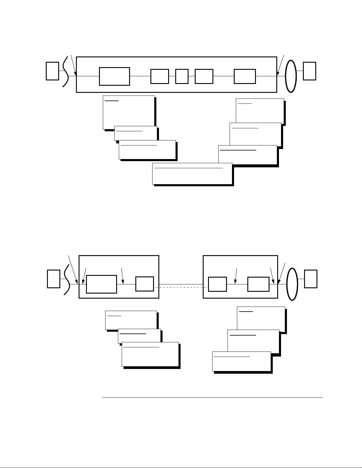
Examples
Figure 18 shows an example of a PathBuilder S24x, 26x, and 27x swit ch co nfi gur ed
for Translational Bridging between an Ethernet and Token Ring Network within the
same node. The records and parameters that need to be configured for Translational
Bridging are shown.
Note
In this example, the parameters in Bridge Link 1 and Bridge Link 2 records
remain at their default values. However, to implement the default settings, you
need to call up the records (from the CTP) and then save them.
Bridging 37
T0008-16F Release 5.2M
Page 42
Configuring the PathBuilder S200 Series Switch for Bridging Operation
Station A Station B
Port 13
Bridge
Link 1
Transparent
Bridge
Link 5
Bridge
PB S200 Switch
LCON
1
PVC
LCON
2
Bridge
Link 6
Source
Bridge
Bridge
Link 2
Port 19
Ethernet
Port 13
Port Type: ETH
Bridge Link Number: 1
Bridge Link 5
Bridge Type: TB
LAN Connection 1
LAN Forwarder Type: BRID
Bridge Link Number: 5
Port 19
Port Type: TR
Ring Number: 1
Bridge Link Number: 2
Bridge Link 6
Bridge Type: SR
Link Mode: TRANS
Virtual Ring Number: 2
LAN Connection 2
LAN Forwarder Type: BRID
Bridge Link Number: 6
Network Services PVC Setup Table
Source: LCON-1
Destination: LCON-2
Token Ring
Figure 18. Translational Bridging Example
Figure 19 shows a situation where a PathBuilder S24x, 26x, and 27x switch is
configured for tra nslational bri dging with SVCs/ PVCs originati ng from two re motes.
Multiple remote Ethernet and Token Ring LANs may attach to the local Token Ring
via the PathBuilder S24x, 26x, and 27x switch with Translational Bridging.
Port 13
Station A
Ethernet
Bridge
Link 1
Transparent
Bridge
PB S200/Node 100
Bridge
Link 5
LCON
X.25/FR Annex G
1
PB S200 Switch w/Translational
Node 200
Bridge
Link 5
LCON
1
Bridge
Link 1
Source
Bridge
SVC
Port 13
Port Type: ETH
Bridge Link Number: 1
Bridge Link 5
Bridge Type: TB
LAN Connection 1
LAN Forwarder Type: BRIDG
Bridge Link Number: 5
Remote ID: 1
LAN Connection 1
LAN Forwarder Type: BRID
Bridge Link Number: 5
Port 19
Port Type: TR
Ring Number: 1
Bridge Link Number: 1
Bridge Link 5
Bridge Type: SR
Link Mode: TRANS
Virtual Ring Number: 2
Figure 19. Translational Bridging Point-to-Point Example
Port 13
Station B
Token Ring
38 Bridging
Page 43

Configuring the PathBuilder S200 Series Switch for Bridging Operation
Bridge Frame Handling
Introduction This section summarizes how PathBuilder S200 series switches handle frames
during Source Route Bridge operation.
How Frame
Handling Works
Broadcast Frame
Handling
Once a PathBuilder S200 series switch station connected to a Token Ring and is
operating normally, non-MAC frames are copied from the ring as they pass through
the bridge station only if they satisfy these requirements:
• The Routing Information Present bit must be set in the source MAC Address
of the frame.
• If the frame is non-broadcast, the local ring number, bridge number, and
remote ring number must match the bridge's stored values for these numbers,
and the routing field must have less than 7 to 14 LAN/bridge couplets
(depending on the configured maximum allowed).
• If the frame is si ngle r oute b roadca st and f or warding of single route br oadcast
is enabled, t hen the Routing Information field must not contain the remo te
ring number since the frame has already been on the forward ring. If single
route broadcast is disabled, the frame is not copied.
• If the frame is All Route Broadcast, then the Routing Information field must
not contain the remote ring number.
These rules apply t o frames with ei ther l oca lly or univer sall y admi nist ered ad dre sses
and for frames with either individual or group addresses.
When the All Route Broadca st frame is received from the LAN and initiated by
another device on the LAN, it is sent to all remote bridges on all SVCs.
The single route broadcast frame is sent only to the remote bridge that is part of the
spanning tree. The specific route frame is sent to the remote bridge via the single
SVC that connects the bridges.
When received from the WAN, broadcast frames are sent to the Token Ring. They
are sent to the other SVCs for general or spanning tree distribution, as appropriate,
after the LAN port removes the frame from th e local ring.
Routed Frame
Handling
When a specifically routed frame is received from the WAN, it is sent to the Token
Ring if the next bridge li sted i n the Rout ing Inf ormatio n fiel d does not correspond to
a bridge formed by a local SVC. Otherwise, it is forwarded to the proper SVC for
additional bridgi ng with out be ing se nt t o the LAN. This keeps trans it t raf fi c of f rings
where it can be avoided.
Bridging 39
T0008-16F Release 5.2M
Page 44

Configuring the PathBuilder S200 Series Switch for Bridging Operation
Configuring Source Route Bridging Operation
Introduction Y ou configure a no de for Source Rout e Bridging dur ing normal bridge c onfigurati on.
Refer to “Configuring the PathBuilder S200 Series Switch for Bridging Operation”
section on page 21 for more details.
This section provides some gui delin es you shoul d conside r when configur ing a node
for Source Route Bridge operation.
Configuring the
Node for SRB
Operation
Individual Bridge
Links
The Node must be enabled for Bridge operation and some general parameters
established in the “Software Key” and “Node Record” sections of the configuration
menu.
• Make sure the CSK is entered for Source Route Bridging (SRB).
• The subaddress within the node for the bridge module should be specified.
This allows the bridge connections to other nodes to be targeted to the right
subaddress upon entering the node.
• A Codex Proprietary Protocol ID must be specified in the Node Record to
ensure that calls for other traffic types, if mistakenly connected to the bridge
subaddress, are rejected. Only similar remote bridges must identify
themselves with this ID.
For details on configuring the Node record, refer to the PathBuilder S200 Series
Basic Protocols.
Once you complete node and port configuration, individual bridge links to other
nodes must be established, up to a maximum of 32 per node. Figure 20 shows LAN/
WAN Bridge Links used in a PathBuilder S200 series switch LAN network.
WAN Bridge Link-Numbered 5 to 36 for
32 possible WAN Links. One link for each
connection to a remote half bridge.
WAN
Adapter
Port-X.25, MX.25,
FR or XDLC
WAN
Network
Token
Ring
LAN
LAN Bridge LinkNumbered 1, only 1
link is operational.
Port
55
1
LAN
Port
LAN
Bridge
5
6
7
8
9
10
SVCs-Connect each half bridge across the
WAN to a remote ha lf bridge.
Figure 20. LAN/WAN Bridge Links Used in PathBuilder S200 Series
Switch LAN Network
To assist you in configuring the node, the LAN bridge-oriented parameters are
considered separate from the WAN-oriented parameters:
40 Bridging
Page 45

Configuring the PathBuilder S200 Series Switch for Bridging Operation
• LAN Side: The LAN port connection consists of one link. To configure the
bridge module requires that you configure the LAN Port; the LAN Bridge;
and the LAN Bridge Link, which passes the LAN traf fic from the LAN Port to
the LAN Bri dge (always numbered “1”).
• WAN Side: The WAN Adapter (default subaddress 94) is used to make the
transition from the LAN to the WAN. The WAN links are numbered 5 to 36
and provide up to 32 WAN connection links which correspond to potential
bridges. These links pass the LAN traffic from the LAN Bridge to the WAN
Adapter. Refer to the sections on Bridge software modules and links for mor e
information.
• WAN Adapter: The WAN Adapter adapts LAN traffic to WAN protocols. It
also provides other WAN services for the bridge, s uch as est ablishing ne twork
calls via a set of configurable records.
Bridging 41
T0008-16F Release 5.2M
Page 46

Configuring the PathBuilder S200 Series Switch for Bridging Operation
Connecting a Station to a Server in Source Ro ute Bridging
Introduction The following is an example of the process involved in establishing a connection
between a station on one Token Ring LAN with a server on a remote Token Ring
LAN for a Source Route Bridging operation.
Procedure These steps describes the process of how a a station to server connection is set up:
1) The PC station (sour ce) on LAN AAA r equests a s ession t o a serve r (dest ination)
located on remote LAN CCC (Figure 21).
PC
LAN
AAA
PB S200
Bridge
WAN
Network
PB S200
Bridge
PB S200
Bridge
PB S200
Bridge
LAN
xxx
Server
LAN
CCC
LAN
zzz
Figure 21. Example of a Station to Server Configuration
2) The PC assumes the server i s on t he loc al LAN, and t he PC sends an LLC frame
(typically an LLC1 TEST frame) around its local LAN AAA looking for a
response from the server. The TEST frame has a destination MAC Address equal
to the server’s MAC Address. Since the server is not on the local ring, no station
responds to the server’s destination MAC Address (Figure 22). This TEST frame
does not have the Routing I nformatio n Indi cator bi t (RII) set (t he high or der bit in
the Source MAC Address) and as a r esult, it does not build a Rou ting Informat ion
Field (RIF) to trace the path to the destination.
42 Bridging
Page 47

Configuring the PathBuilder S200 Series Switch for Bridging Operation
Frame
PC
?
LAN
PC
?
AAA
PB S200
PC
?
PC
?
Figure 22. Server’s Destination MAC Address Not on LAN AAA
3) After receiving no response on the local LAN, the PC uses Source Route
Bridging (SRB) to find the path to the remote server. The PC can resend the
TEST frame indicating that the frame is to be bridged over all routes.
The PC resends an All Route Explorer (ARE) TEST frame via its SRB software
(Figure 23).
PC
?
LAN
AAA
ARE Frame
PB S200
Figure 23. All Route Explorer (ARE) Frame Searches the Network for
the Server
4) The TEST frame includes the following:
• Destination Address is server's MAC Address.
• Routing Information Indicator bit (RII) is set to one. This bit is the mo st
significant bit in the source address, indicating this frame has a Routing
Information Field (RIF).
• Three bit s in the Routi ng Information Field (RI F) indicate th is is an ARE.
This instru cts all bridges that enco unter this frame to forward the frame to
their destination LANs. This form of broadcast ensures that at least one copy
of the frame arrives at the destination.
• Routing Information Field (RIF) shows the path (LAN number/Bridge
number, LAN number/Bridge number, etc.) that each ARE frame took on its
search between the source and the destination.
Bridging 43
T0008-16F Release 5.2M
Page 48

Configuring the PathBuilder S200 Series Switch for Bridging Operation
5) The PathBuilder S200 series switch transfers a copy of the ARE frame from the
LAN Port across LAN Bridge Link number 1 to the Bridge (Figur e 24). Since the
frame is an All Routes Explorer, the Bridge broadcasts the frame across each of
the existing WAN Bridge Links (32 max) to the WAN Adapter module.
6) The WAN Adapter transmits each ARE frame to a separate, already established
SVC which connects it across the WAN to a remote node (Figure 25). Note that
in the node attached to LAN AAA, three bridge links (5, 6, and 7) to the WAN
side are necessary because they go to the three remote LANs to establish
complete bridges to thos e LANs. The three right-hand node s really need only one
WAN Bridge Link each, but two additional ones are shown; they could be
attached to other bridges in other nodes not shown.
LAN Bridge Link
PC
LAN
AAA
Port
55
Bridge
1
WAN Bridge Links
5
6
7
WAN
Adaptor
ARE Frame
ARE Frame
ARE Frame
WAN
Port
SVCs
(PVCs for Frame Relay)
Figure 24. PathBuilder S200 Series Switch Transfers a Copy of ARE
Frame to the Bridge Module
44 Bridging
Page 49

Configuring the PathBuilder S200 Series Switch for Bridging Operation
PB S200
Bridge
WAN
Adaptor
5
6
7
LAN
Port
1
LAN
xxx
PC
LAN
AAA
PB S200
LAN
Port
1
WAN Bridge Link
PB S200
Bridge
5
6
7
WAN
Adaptor
WAN
Network LAN
WAN
Adaptor
Bridge
5
6
7
LAN
Port
1
LAN Bridge Link
PB S200
Bridge
WAN
Adaptor
5
6
7
LAN
Port
1
Figure 25. WAN Adapter Transmits Each ARE Frame Across the WAN
Server
CCC
LAN
zzz
7) One of the ARE frames finds the des tinatio n server, and the server recognizes the
MAC address in the TEST frame.
Bridging 45
T0008-16F Release 5.2M
Page 50

Configuring the PathBuilder S200 Series Switch for Bridging Operation
8) The server issues a Specific Route TEST frame (also called a non-broadcast
frame) in response using the route indicated in the ARE TEST frame. Note that
the server does not have to b roadcast (use ARE) t o get the TEST re sponse bac k to
the PC; it uses a Specifically Routed TEST frame (Figure 26).
PC
LAN
AAA
PB S200
LAN
Port
1
PB S200
Bridge
Bridge
5
6
7
WAN
Adaptor
WAN
Network
WAN
Adaptor
5
6
7
LAN
Port
1
Figure 26. Server Responds with Specifically Routed TEST Frame
9) The response TEST frame also has a Routing Information Field (RIF) with the
same path trace as the o rigin al ARE TEST fr ame exce pt the Di rect ion bit is se t to
1. This reverses the direction in which the RIF sequence is read and indicates the
path back to the source. The RIF also se ts three bit s in the Routing Type field that
indicate the frame is to be specifically routed and not broadcast.
10) When the response TEST frame reaches the source PC, the PC now knows what
route to use to send its frames to the server.
Server
LAN
CCC
46 Bridging
Page 51

Configuring the PathBuilder S200 Series Switch for Bridging Operation
Attaching a Station
to a Ring
This table describes how a station attaches to a ring.
Step Action Result/Description
1 The station requests values for the
ring’s operational parameters from
the RPS.
2 An attaching station also sends the
RPS its adapter software level as
well as its Upstream Neighbor
Address.
If... Then...
An RPS is
present on the
ring,
It responds to
the station’s
request by
The RPS then notifies the LAN
managers that a new station has
attached to the ring.
sending it the
current values
for the ring’s
operational
parameters.
An RPS is not
present on the
ring,
The ring station
uses the values
assigned by the
An RPS has a functional address of
C00000000002.
program using
the ring station
or the default
values for its
operational
parameters.
Bridging 47
T0008-16F Release 5.2M
Page 52

Transparent Bridging for Ethernet LANs
T ransparent Bridging for Ethernet LANs
Introduction A transparent bridge, also known as a spanning tree bridge, decides where to relay
Ethernet LAN frames by using the spanning tree protocol to develop and maintain a
loop-free topology.
Using spanning tree, you can add a bridge anywhere in the Ethernet LAN without
creating loops. The networ k de vic es a re not i nvol ve d in t hi s dec is ion pro ces s, whi ch
is transparent to them.
Learning A transpar ent bridge monitors Ethernet LAN traffic, “learns” th e source address of
each frame it receives, and maintains a database (also known as the Forwarder) of
source addresses and associated bridge connections. A transparent bridge uses a
timeout process to purge its database of what it considers inactive addresses.
For the PathBuilder S200 seri es sw itch t o “le arn” wher e MAC st atio ns are loc ated i n
relation to themselves, they use a ha rdware accel erator, a transparen t bridging
forwarder, and a transparent bridging forwarding table.
A transparent bridge learns based upon the MAC source address. This address is
placed into the transparent bridging forwarder table, along with the link that the
PathBuilder S200 series switch received the frame on, if the address is not to be
filtered.
Tr ansparent Bridge
Forwarder
When a transparent bridge receives a frame, it checks its database fo r the frame
address and performs one of the following actions:
• If the frame’s MAC destination address is not found in the TB forwarding
table, then the bridge s ends the frame on all b ridge co nnections (excep t for the
connection on which it arrived).
• If the bridge has learned the destination address, meaning the frame’s MAC
destination address i s found in th e TB forwarding t able, the n the fra me is sent
out on the learned link, unless there is a filter set on the link.
• The Hardware Accelerator discards local traffic before it reaches the node.
The Forwarder initiates the Learning process of the transparent bridge logic for
frames received from the LAN and WAN ports.
After receiving an Ethernet frame, the Forwarder applies bridging logic, routes the
frame to the appro priate Handler , and s ends the frame to t he outgoi ng link, which is a
path to the frame’s MAC destination address.
The Forwarder:
• Initiates WAN frame learning
• Initiates LAN frame learning
• Filters the frame using the filtering facility
Information sent to the Hardware Accelerator includes:
• Source address
• Destination address
48 Bridging
Page 53

Transparent Bridging for Ethernet LANs
Tr ansparent Bridge
Forwarder Example
A frame arrives at the
TB Forwarder.
YES
Is
the MAC
Source Address in the
forwarding
table?
YES
Is
the MAC
Destination Address in
the forwarding
table?
YES
TB Forwarder checks
if any filters are set.
Figure 27 shows how the Forwarder and the Hardware Accelerator process a frame.
Drop
the frame.
YES
NO
NO
TB Forwarder checks
if any filters are set.
YES
Do
filters
match?
Do
filters
match?
NO
NO
flag for a Unicast or
Source Address on the
Permanent Station
Is
the inbound
Multicast frame
set?
YES
Is
the MAC
Address
List?
NO
Drop
the frame.
NO
YES
Learn the Source
Address.
TB Forwarder gives the
frame to the appropriate
handler as found in the
forwarding table.
Forwarder
Statistics
Do
filters
match?
YES
Drop
the frame.
TB Forwarder gives the
frame to the handlers
that are in the
forwarding state.
NO
Handler sends
the frame.
Figure 27. How the Forwarder and Hardware Accelerator Process a
Frame
In addition, the Forwarder collects the following types of statistics:
• Filtering
• LAN link
• WAN link
• Link error
Bridging 49
T0008-16F Release 5.2M
Page 54

Transparent Bridging for Ethernet LANs
Forwarder/
Hardware
Accelerator and
LAN/WAN Handler s
Hardware
Accelerator
Functions
Figure 28 shows the relationship of the Forwarder and Hardware Accelerator to the
LAN and WAN Handlers.
LAN
Handler TB
1
Forwarder
HW
Accelerator
WAN
Handler
36 32
15
Figure 28. Relationship of Forwarder and Hardware Accelerator to LAN
and WAN Handlers
The Hardware Accelerator performs these functions:
• Discards local traffic before it reaches the node
• Participates in the learning process for LAN traffic
• Participates in the aging process for LAN traffic
The Hardware Accelerator applies the aging process to the learned addresses on a
LAN port. It needs to:
• Set the agin g timer bit for each address learned on the LAN link.
• Reset the aging timer bit fo r the entr y whene ver a frame wit h the same sour ce
address passes through the bridge
• Decrement the aging timer bit when it receives periodic timeout notification
from the Forwarder
• Remove all the aged-out entries from the Hardware Accelera tor database
The statistics which show the number of local traffic frames discarded by the
Hardware Accelerator are displayed on the LAN port Statistic CTP menu.
50 Bridging
Page 55

Transparent Bridging for Ethernet LANs
Forwarder
Functions
The Forwarder bridging logic includes decisions such as:
• Which Link(s) the frame should be sent to.
If the destin ation addre ss of t he fr ame exi sts i n the Fo rwardi ng Table, and there is a
link number associated with it, then the Forwar der checks whethe r filter s should be
applied to the frame and cause the frame to be dropped. If all these conditions are
satisfied and no filters apply, the Frame is sent over to the link via the Handler.
• Whether the frame should be broadcast to all ports, even though the frame is
not a multicast or broadcast frame.
If the destination address of the frame did not exist in the Forwarding Table
(such as when thi s is the first ti me t he bridge learns t he sour ce address of t he frame),
the Forward er attempts to send the frame out over all links which are in Forwarding
state (except the link wher e the fr ame arri ved). Befor e the Forw arder se nds the f rame
out, it also checks whether filters are to be applied to this frame. The frame may get
filtered at certain links.
• Whether the frame is a multicast or broadcast frame, and if it is, to which links
the frame should be sent out.
The Forwarder attempts to send the multicast or broadcast frame over to all links
which are in forwarding state (except the link where the frame arrived). Before
sending the frame out t o each link, the For war der checks with the fi lt ering facilit y t o
see if filters are to be applied to the frame at that link. If not, the Forwarder sends the
frame over to the link. A multicast/Broadcast frame is a frame with the Least
Significant Bit of its destination address being set to 1.
• Whether the received non-multicast and non-broadcast frame should be
dropped without sending it out.
The Forwarder drops the fr ame due t o filte ri ng, when the link is unconfigured or the
link is not in forwarding state.
Forwarder
Initialization
Two types of forwarding database entries that are kept in running memory are:
• Learned (dynamic)
• Permanent (static)
The learned entries of the forwarding database are obtained from the source address
of frames that are received by the bridge entity. This relies on the end stations
sending frames so that the bridge learns the station location from the source address
contained in the frame.
The permanent entries are obtai ned fr om a CMEM r ecord that is c onf igurable by the
system administrator. They are loaded into the database whenever the node or the
table is booted. The permanent entries are maintained by the system administrator.
During Forwarder Module initialization, the Forwarder creates the sockets to
connect to other modules in the node, such as sockets used to communicate with the
network handlers. It also defines MACRO services in the Forwarder Module
Descriptor to export the socket addresses to the outside world.
Bridging 51
T0008-16F Release 5.2M
Page 56

Transparent Bridging for Ethernet LANs
Forwarder and
STPE
The Forwarder cleans up al l entrie s in the Forw arding Table when there are spanning
tree topology changes taking place. These actions are considered services the
Forwarder provides to the Spanning Tree Protocol Entity (STPE). The Forwarder
provides these services through MACRO routines so that they are accessible to the
entire system.
Note
The Forwarder is not required to pass STPE traffic to the handlers. The STPE is
considered to be an independent entity a nd similar to all the forwarders in the
system. It has its own interface with the network handlers and it uses this
interface passing PDUs to the network via the handlers. For example, it forwards
Spanning tree PDUs directly to the handler and does not go through the
Forwarder.
Learn Only Period The Learn Only Period is a ti mer you can set fr om the CTP. This timer is started
whenever the node boots. Until thi s timer expires, the bridges learn onl y LAN station
addresses and place them into the forwarding database. The bridges do not forward
any frames during this interval. When the timer expires, the bridges forward frames
in the usual w ay. The default setting for t his parameter is 10 seconds.
This timer is not to be confused with the Forward Delay timer of the spanning tree
protocol entity (STPE). The STPE timer is used to control how long a bridge link
withholds a link from going into the forward state once it is determined that the link
should be part of the spanning tree. This timer is set to avoid bridge topology loops
from forming. The Learn Only Period timer prevents the bridge from sending
broadcasts (as par t of t he lea rning pr ocess ) whe n the br idge f irst c omes up, and has a
sparse forwarding database.
Aging Aging is an important process associated with the learned da tabase entrie s. When a
new entry is learned and placed in the forwarding database, a timer is set that
indicates the station with the MAC address is still active. If the timer expires for an
entry, the entry is removed from the database. The aging time for learned entries in
the forwarding table is configurable by the system administrator. This parameter is
located in the Bri dge Parame ters me nu. The def ault set ting for this para meter i s 3600
seconds (1 hour).
The Forwarder starts the Aging Timer for the learned addresses in the Forwarding
Table.
The purpose for aging database entries is to allow changes in the network
configuration t o be auto matica lly accou nted fo r in t he forwar ding t able. If a stati on is
moved from one LAN to another, the station becomes reachable when the entry ages
out and is replaced with a new entry that indicates new forwarding information.
Aging does not apply to the per manen t en trie s in the forw ardin g table . The se entr ies
are maintained by the sys tem admini stra tor and kept in CMEM. They are never ag ed
out of the forwarding database and they are never corrected. If a frame arrives on an
unexpected link with a source address in the permanent part of the forwarding table,
the table is not changed.
52 Bridging
Page 57

Transparent Bridging for Ethernet LANs
Forwarder Database and Spanning Tree
How They Work
Together
There is a close relationshi p bet w een the f orwa rdi ng dat ab ase and the spanning tree.
The spanning tree can be ma nually conf igured. This is a reasonab le thin g to do in the
case where a stable environment exists since it saves CPU processing by eliminating
aging timers and the broadcasting that is employed when the forwarding table does
not have a suitable entry. In this case, when the node is booted, bridges will form a
spanning tree (always the same one provided all equipment remains operational),
and a permanent forwardi ng data base ca n be lo aded from CMEM that is re quired for
the configuration. This also allows a quick method for the bridge to become
operational.
The learning process continues even if the forwarding table is formed initially from
permanent CMEM entries. That is, the forwarding database adds learned entries as
they occur; if there are stations active that are not in the initial database, they will be
added as they are learned. Such an expanded database can be written to the CMEM
by a CTP update command. This has the effect of converting the entire forwarding
table in runnin g memor y t o p ermanent entries and creating a new per m anen t table in
CMEM equal to the running configuration.
If the spanning tree is configured for automatic configuration, then the operation of
the forwarding database is as noted previously. The permanent database offers a
means of quickly obtaining a forwarding database without the bridge having to
broadcast frames for whi ch it doe s not know t he desti nati on link . However, since the
bridge topology can change in an unpredi ctable way (correspondi ng to unpredi ctable
network failures), it is best that the entries in the database ar e all aged. Aging all
entries allows the forwarding database to remain current even with topology
changes. Therefore, it is re commended that if such change s are expected, the syst em
administrator should not use permanent forwarding entries. However, there is no
reason that they canno t be use d, and th e fu ll se t of edi ting and s aving c ommands s till
apply when the spanning tree is in automatic operation.
Deleting
Forwarding Table
Entries
Forwarding table entries can be deleted from CMEM by CTP command. If the
system administrator change s the t opolog y (cha nges br idges o r sta tions), t he CMEM
record (edit, delete, add) can be updated and the table booted to get a cleaned up
version of the database in working memory. This boot does not disrupt bridge
operation other than a momentary disruption to forwarding traffic.
The entire forwarding table in CMEM can also be deleted by a single CTP
command. This lets you make substantial changes to the topology, then boot the
bridge network (with no permanent forwarding table entries) to let the bridge learn
station locations. After a suitable learning time, you can update the entries to
permanent CMEM entries using the update command. From that point on, the
permanent forwarding table will contain valid entries for the configuration.
Bridging 53
T0008-16F Release 5.2M
Page 58

Transparent Bridging for Ethernet LANs
Using Filters
Support The Forwarder provide s its own fil tering faci lity whic h is used to red uce unneces sary
traffic and to provide security. The filtering facility supports the following types of
filters:
• Incoming Source Address Filter
• Incoming Destination Address Filter
• Outgoing Source Address Filter
• Outgoing Destination Address Filter
Incoming Source
Address Filter
Incoming
Destination
Address Filter
Outgoing Source
Address Filter
Outgoing
Destination
Address Filter
Unicast Link
Protect Flag
The Incoming Source Address Filte r fil ters pac kets ar e base d on thei r sour ce addr ess
and incoming links. Frames with a source address found in the Incoming Source
Address Filter List are discarded without applying bridge logic. This filter may be
applied to all links or selected links.
The Incoming Destination Address Filter filters packets based on their destination
address and the incoming ports. Frames with a destination address found in the
Incoming Destination Address Filter List are discarded without applying bridge
logic. This filter may be applied to all links or selected links.
The Outgoing Source Addres s Filte r filters packets b ased on th eir sour ce address and
the outgoing links. Frames with a source address found in the Outgoing
Source Address Filter List are discarded. This filter may be applied to all links or
selected links.
The Outgoing Destination Address Filter filters packets based on their destination
address and the outgoing links. Frames with a destination address found in the
Outgoing Destination Addres s Filte r List are disc arded. Thi s filt er may be appli ed to
all links or selected links.
When a frame comes from a link with the Unicast Link Protect Flag set, and if its
source address is not found in the Permanent Station Address list, the frame is
dropped.
When a frame is being sent out over a link with the Unicast Link Protect Flag set,
and if its destination address is not found in the Permanent Station Address List, the
frame is dropped.
Once the Unicast Link Protect Flag is set for a link, source address learnin g for
Unicast frames is sto pped for that link and al l th e addr esses that were lear ned be for e
are moved into the Permanent Station Address List.
Setting or Clearing of Unicast Link Protect Flag is performed via the LAN Control
menu located in the Main menu.
54 Bridging
Page 59

Transparent Bridging for Ethernet LANs
Multicast Link
Protect Flag
When a multicast/br oad cast frame comes fr om a l in k wit h t he Multicast Protect Flag
set, and if its source address is not found in the Permanent Station Address list, the
frame is dropped.
When a multicast/broadcast frame is sent out over a link with the Multicast Protect
Flag set, and if its destinati on ad dress is not found in the Permanent Station Address
List, the frame is dropped.
Once the Multicast Protect Flag is set for a link, source address learning for
multicast/broadcast frames is stopped for that link totally and all the addresses that
were learned before are moved into the Permanent Station Address List.
Setting or Clearing of Multicast Link Protect Flag is performed using the LAN
Control menu located in the Main menu.
Bridging 55
T0008-16F Release 5.2M
Page 60

Transparent Bridging for Ethernet LANs
T ransparent Bridge Co nfiguration Parameters
TB Forwarding
Figure 29 shows the Transparent Bridge Forwarding Ta ble parameters.
Table
Node: Address Date: Time:
Menu: Configure Bridge Path:
Bridge Parameters
Bridge Link Parameters
MAC Address Filter Table
Protocol Filter Table
NETBIOS Name
LSS Parameters
TB Forwarding Table
Entry Number
*Local MAC Address
*Bridge Link Number
Figure 29. Transparent Bridge (TB) Forwarding Table Menu
Parameters These parameters make up the Transparent Bridge Forwarding menu.
Entry Number
Range: 1 to 8000
Default: 1
Description Entry used to reference this table record.
*Local MAC Address
Range: 00-00-00-00-00-01 to FF-FF-FF-FF-FF-FF
Default: 00-00-00-00-00-01
Description MAC Address that is to be used for forwarding.
Bridge Link Number
Range: 1, 5 to 36,
Default: 1
Description The bridge link to forward a frame with the associated MAC
Address.
Boot Type: Perform a node boot to implement changes to this parameter.
56 Bridging
Page 61

Bridge Filtering
Bridge Filtering
What is It? Bridge filtering prevents extraneous traffic from traversing the WAN and stops the
unintentional proliferation of traffic onto other remote LAN segments.
In Ethernet T ran sparen t Bridgin g, the broa dcast fe ature lets st ations d etermine routes
to other end stations. Broadcasting to the entire network can unnecessarily degrade
performance becau se of b roa dcasts traversing LAN s egme nts that are not in any part
of the network where the target station resides.
Therefore, you can use bridge filtering methods such as MAC Address Filtering,
Protocol Filtering, and NetBIOS Name Filtering to control broadcast traffic and
reduce overhead.
How Filtering is
Used
Filtering is used to:
•Reduce
Filtering broadcasts can help to reduce this overhead.
• Control the unnecessary proliferation of application level broadcasting used
on Novell and NetBIOS applications.
• Restrict access to certain LAN segments for security reasons.
• Prevent unnecessary traffic from proliferating onto the WAN where
bandwidth is limited. This can help to reduce congestion and minimize delay
for traffic that must cross the WAN.
• Prevent stations usi ng a certain pr otocol from oper ating ou tside thei r intended
scope. Protocol formats that are filtered include DSAP and SNAP.
You can filter the MAC address contained in a frame or a protocol. The system
applies MAC address filtering first and then follows with protocol filtering if
appropriate.
MAC Address filtering can be performed on either the source address or destination
address.
unnecessary traffic affecting the performance of LAN segments.
Bridging 57
T0008-16F Release 5.2M
Page 62

Bridge Filtering
MAC Address Filtering
What Is It? This feature lets you filter bridge traffic based on MAC address.
The Bridge Link Table and the MAC Address Filter Table are used to configure
MAC Address filtering.
The Bridge Link Table specifies:
• Whether or not any filtering action is to be performed.
• The filtering action to perform when the MAC frame address is not found in
the MAC Address Filter Table.
The Bridge Link Table contains these parameters, including the MAC Address
Filtering Action parameter, which lets you specify the filtering actions to be applied
at the bridge link. These parameters are located under the Configure Bridge Link
menu selection:
• Entry Number
• Bridge ID
• Hop Count Limit
• Largest Frame Size
• MAC Address Filter Action
• Protocol Filter Action
• STPE Link State
• STPE Priority
• STPE Path Cost
MAC Address Filter
Table Parameters
The MAC Address Filter Table specifies:
• The MAC Address of the frame to be filtered.
• The filtering action to perform on the frame.
This table is used in conjunction with the Bridge Link Table to specify filtering
action and includes the link action parameters which allow you to apply filtering
action to every link.
This table describes the MAC Address Filter Table parameters.
Parameter Action
MAC Address Frames that have MAC Addresses matching this MAC
Address are filtered as specified by the parameters in this
table.
Incoming Source
Address Link Action
Outgoing Source
Address Link Action
Incoming
Destination Address
Link Action
Perform filtering action on an inbound frame having the
indicated MAC Source address.
Perform filtering action on an outbound frame having the
indicated MAC Source address.
Perform filtering action on an inbound frame for the
indicated MAC Destination address.
58 Bridging
Page 63

Parameter Action (continued)
Bridge Filtering
MAC Address
Filtering Action
Parameter
Selections
Outgoing
Destination Address
Perform filtering action on an outbound frame for the
indicated MAC Destination address.
Link Action
List of Links Sp ecifi es t he li nks a ssoci ated with t he pr ecedi ng li nk act io n
parameters in this ta ble. When Pass list (PL) is spec ified, the
associated listed links pass the frame and the unlisted links
block it. Conversely, when Blocklist (BL) is sp ecified, the
associated list ed links block the frame and the unlist ed links
pass it.
This table lists the filtering actions available for the MAC Address Filtering Action
parameter.
Parameter
Action
Value
Pass (P) Look in th e MAC Address F ilter Table for an entry with a matchi ng
MAC frame address and perform the filtering action specified by
this entry. If no matching MAC frame address is found, pass the
frame.
Block (B) Look in the MAC Addres s Filter Table for an entry with a matching
MAC frame address and perform the filtering action specified by
this entry. If no matching MAC frame address is found, block the
frame.
What Happens
During Filtering
None (N) No filtering to be performed; pass the frame.
When filtering is performed, the system checks the Bridge Link Table of the bridge
link involved with the frame to se e if the MAC Address Filtering Act ion parameter is
configured to disable all filtering on that bridge link. Figure 30 shows the process
involved in MAC Address filtering.
If the parameter is configu red t o d is able filtering ( NONE selected), then the frame is
allowed to pass and no filtering is applied.
If the parameter is configured with another value, either PASS or BLOCK, this
signifies that the MAC Address Filter Table is to be checked to determine whether
filtering action is to be performed. In this situation, the frame is checked to see if a
match occurs between the MAC address in the frame and an address contained in an
entry in the MAC Address Filter Table.
Bridging 59
T0008-16F Release 5.2M
Page 64

Bridge Filtering
MAC Filtering
Process
Figure 30 shows the MAC Filtering process.
Check Bridge
Link Record or Entry
NONE
Pass frame
without
filtering
Apply Table Filter:
PASS or
BLOCK
YES
MAC Address
Filtering Action
Setting?
PASS or BLOCK
Check MAC Address
Filter Table for match
of frame MAC Address
Frame MAC
Address in MAC
Address Filter
Table?
NO
Check Bridge
Link Table
MAC Address
Filtering Action
Setting?
PASS
Pass the
frame
BLOCK
Block the
frame
Figure 30. MAC Address Filtering Action
60 Bridging
Page 65

Bridge Filtering
Mac Filtering
Process
Incoming and
Outgoing Frames
As shown in Figure 30, if a match is detected, the system applies the filtering action
configured for that e ntry. The filtering action is to either PASS the frame or BLOCK
the frame for all links or for a configured list of links. This filtering action overrides
the action specified in the MAC Address Fil ter Action para meter.
If there is no match between the frame MAC Address and any entry in the MAC
Address Filter T able, then filtering action on that frame is not controlled by the MAC
Address Filter Table.
When the filtering action is not controlled by the MAC Address Filter Table, the
action taken by the bridge is determined by the MAC Address Filter Action
parameter in the Bridge Link Table; the action is to either PASS the frame or
BLOCK it.
The MAC Address Filter Action parameter determines if the filter table is enabled on
a bridge link. This same parameter is used to define the action taken (PASS or
BLOCK) when no match is made in the MAC Address Filter Table.
For a detailed description of the MAC Addre ss Filter parameters, refer to
“Configuring the MAC Address Filter Table” section on page 66.”
The filtering actio n is appli ed to each l ink. The frames pas sing on a li nk can be ei ther
incoming or outgoing (see Figure 31). Incoming means that the frame is entering the
bridge from elsewhere either from the LAN or WAN. Outgoing means the frame is
leaving the bridge. Therefore, a given frame can be incoming on one link and
outgoing on another link (provided it does not get blocked due to filtering).
Filtering can be applied at each of those links.
For any link, the PASS or BLOCK attribute can be set for either the source address
or the destination address. This method allows you to individually configure every
combination of i n/out and sourc e/desti nation t o eithe r a p ass or a block a ction f or any
link.
Bridge Links
Token
Ring 1
Outgoing Frame
(from Bridge)
Frames passing on a link can be either incoming or outgoing.
The same frame can be inc oming on one link and outgoing on another lin k.
Bridge
Incoming Frame
(to Bridge)
WAN
Network
Figure 31. Example of a Frame Passing on a Bridge Link
The source address (incoming or outgoing) refers to the frame having the indicated
MAC source address. The destination address (incoming or outgoing) refers to the
frame havi ng the indica ted MAC destination addr ess.
Bridging 61
T0008-16F Release 5.2M
Page 66

Bridge Filtering
MAC Address Filtering Examples
Introduction This section shows two filtering examples. Figure 32 shows how the source address
can be used to fil ter fr ames. Fig ure 35 shows how the MAC Address Filter Table can
be used to filter frames by combining multiple source and destination addresses.
First Example In Figure 32, the source address (MAC Address represented by A) is used to filter
frames passing in or out of the bridge via links 1, 5, and 6 (Figure 32). Frames
originating from the station with MAC Address A are to be sent to server B but not
server C. Figure 32 shows that for bridge link 1, Incoming Source Address frames
with MAC Address A are passed, and Outgoing Source Address frames with MAC
Address A are passed on link 5, but blocked on link 6.
Source Address
A
PB S200
Token
Ring 2
Token
Ring 3
B
C
Token
Ring 1
Incoming
Source
Pass
1
Bridge
Pass
5
Outgoing
Source
Outgoing
Source
6
Block
PB S200
PB S200
How To Configure
the Example in
Figure 32
Incoming Sour c e Address: Pass Link 1
Outgoing Source Address: Pass Link 5; Do Not Pass L ink 6 (Block)
Figure 32. Example of Bridge Links Configured to Filter Selected MAC
Address Frames
T o configur e something s imilar to F igure 32, complete the Bridge Li nk record fo r the
bridge and the MAC Address Filter Table as shown in these tables.
Configuring the Bridge Link Record
Parameter Values
Entry Number 156
MAC Address Filter Action Pass Pass Pass
62 Bridging
Page 67

Bridge Filtering
Configuring the MAC Address Filter Table
Parameter Values
Entry Number 1
MAC Address A
Incoming Source Address Action Passlist
List of Links 1
Outgoing Source Address Action Passlist
List of Links 5
In a Bridge Link Recor d, Pass (or Bl ock) tell s the syste m to check the MAC Addr ess
Filter Table to find out what filtering t o perf orm. If t he Brid ge Link Record s pecif ied
None, then the frame would pass without any filtering.
If the frame MAC Address is in the MAC Addre ss Filter Table, filtering is performed
on the frame as specified in this table. The MAC Address Filter Table used in this
example specifies the filtering to be performed on MAC Address A as the incoming
source address to the bridge. Frames with Incoming Source Address A are passed at
link 1 (see Figure 32). Frames with Outgoing Source Address A are passed at link 5
(to server B), but not passed on link 6 (to server C).
Bridging 63
T0008-16F Release 5.2M
Page 68

Bridge Filtering
W
Identifying Address Links for MAC A ddressing
Why it is Important Identifying the address links is an important step in configuring MAC Address
filtering.
A Source Address link allows a device on the LAN to send frames. A Destination
Address link allows a device on the LAN to receive frames.
The Incoming Source Address link provides a path for a f rame t o go f rom th e Token
Ring to the bridge. The Out goi ng Source Address link pro vide s a pat h for a frame to
go from the bridge to the WAN.
The Incoming Destination Address link provides a path for a frame to go from the
WAN to the bridge. The Outgoing Destination Address link provides a path for a
frame to go from the bridge to the LAN.
Example of
Address Links
Figure 33 shows that link 5 serves as both the Outgoing Source Address link and the
Incoming Destination Addre ss link. In this exampl e, Outgoing Source Address link 5
allows the File Server with MAC Address 10:00:5A:00:00:40 (the source) to send
frames to the WAN via li nk 5. Incoming Destination Address link 5 allows the File
Server with MAC Address 10:00:5A:00:00:40 (the destination) to receive frames
from the WAN via link 5.
Outgoing Source Address Link (MAC Address 10:00:5A:00:00:40)
Incoming Destination Address Link (MAC Address 10:00:5A:00:00:40)
Incoming Source Address Link (MAC Address 10:00:5A:00:00:40)
Outgoing Destination Address Link (MAC Address 10:00:5A:00:00:40)
AN
5
Bridge
6
Node 100
1
Token
LAN
Ring 2
MAC Address 10:00:5A:00:00:40
File Server
Figure 33. Example of Address Links
64 Bridging
Page 69

Bridge Filtering
MAC Wildcard Filtering
What Is It? MAC wildcard filtering is an enhancement to the Motorola Network Access
Products MAC Filter table. MAC wildcard filtering lets you configure the MAC
filter tables and use wildcards “*” to designate numeric pieces of the MAC address.
The MAC Address filter lets you configure a table of MAC Address filters (each
filter contains a MAC address which is a string of 12 characters from the range 0-9,
A-F). The table is searc hed for eac h incoming an d outgoing f rame on the LAN/ WAN
link to find a match in the tab le for the MAC address in the frame.
This enhancement lets you use the wildcard character “*” in any of the 12 character
positions while configuring a filter. The wildcard character matches any of the valid
characters allowed in a MAC address (0-9, A-F) when it is used to filter a given
MAC Address.
MAC wildcard filtering lets yo u config ure a smaller MAC Addr ess Fil ter ta ble if you
configure MAC Address filters where one or more of the 12 character positions can
be allowed to take any va lue in the permissible range.
For example, with the existing functionality, if the Bridge had to be configured to
block all the frames with MAC addresses in the range 080004001F00 to
080004001FFF, you would have to configure 256 filters. Now you can simply
specify 080004001F**.
PathBuilder S200
Series Switch
Support
How MAC Wildcard
Filtering works
PathBuilder S200 series swit ches support the MAC wildcard featur e on t he Et her net .
Figure 34 shows a typical MAC wildcard filtering application:
080004001F05
080004001F04
080004001F03
080004001F01
080004002F01
080004001F02
Figure 34. Example of How MAC Wildcard Filtering Works
With the old filtering system, if you do not want any of the devices shown on the
LAN on the left to access the WAN, you would need to configure all five entries.
With the MAC wildcard filtering, only one entry is required. For example, you can
specify 080004001F** to pr event all devices from accessing the WAN.
Bridging 65
T0008-16F Release 5.2M
Page 70

Bridge Filtering
Configuring the MAC Address Filter Table
Introduction The MAC Address Filter Table controls which frames are allowed to pass on to
different link s and le ts you cont rol pro pri et ar y inf ormat i on tha t you may not want to
go to another LAN. It is also useful in controlling the unnecessary proliferation of
broadcast frames in the LAN network.
MAC Address Filter
Figure 35 shows the MAC Address Filter Table parameters.
Table Parameters
Node: Address: Date: Time:
Menu: Configure Bridge Path:
Bridge Parameters
Bridge Link Parameters
MAC Address Filter Table
Entry Number
MAC Address
Incoming Source Address Link Action
Outgoing Source Address Link Action
Incoming Destination Address Link Action
Outgoing Destination Address Link Action
Figure 35. MAC Address Filter Table Menu
Categories MAC Addresses can fall into four categories:
• Incoming Source
• Outgoing Source
• Incoming Destination
• Outgoing Destination
Every node (bridge) has one MAC Address Filter Table. Every bridge link can be
configured to determine whether or not frames passing on that bridge link are to be
filtered according to the entries in the MAC Address Filter Table.
The filter table is examined to see if there is a match. If a ma tch is found (table and
frame), additional table parameters determine when to pass or block the frame.
If there is no match, the decision is dependent upon the Bridge Link record to
determine whether to pass or block.
Action is then taken on what is specified in this record (pass or block), rather than the
filter table , when there is no match to an ent ry in this filter table.
Note
A Table boot is required to make MAC Address Filter parameters part of an
active configuration. Booting is nondisruptive to data or call connections.
66 Bridging
Page 71

Parameters These parameters make up the MAC Address Filter Table.
Entry Number
Range: 1 to 300
Default: 1
Description: Entry number used to reference this table record for filtering
action.
Note
If you do not wish to determine filter action for this link through
the MAC Address Filter Table, select NONE in the Bridge Link
record.
MAC Address
Range: 00-00-00-00-00-00 to FF-FF-FF-FF-FF-FF (Canonical)
Default: 00-00-00-00-00-00
Bridge Filtering
Description: Frames with MAC Addresses that match this MAC Address are
filtered as specified in the following parameters. For an example
of MAC Address Filtering, refer to “MAC Address Filtering
Examples” in this guide.
Incoming Source Address Link Action
Range: PASS, BLOCK, PASSLIST, BLOCKLIST
Default: PASS
Description: Incoming source m eans th at the fram e is en terin g th e bridg e enti ty
from the LAN that includes the MAC address (the source).
Therefore, a given source frame will be incomi ng from the LAN to
the Bridge and outgoing from the Bridge to the WAN (provided it
does not get blocked due to filtering). Refer to Figure 31.
• P ASS: Pass incoming f rames with thi s MAC Address val ue on
all links that are referencing this table. If this value is chosen,
skip the List of Links.
• BLOCK: Block incoming frames with this MAC Address
value on all links tha t are ref erencing t his table . If thi s value is
chosen, skip the List of Links.
• PASSLIST: If this value is used, a pass list is specified by the
following parameter, List of Links. Links in this list pass the
frame. Links not in this list block the frame.
• BLOCKLIST : I f t his value is used, a block list is spe ci fi ed by
the parameter, List of Links. Links in this list block t he frame.
Links not in this list pass the frame.
Bridging 67
T0008-16F Release 5.2M
Page 72

Bridge Filtering
Outgoing Source Address Link Action
Range: PASS, BLOCK, PASSLIST, BLOCKLIST
Default: PASS
Description: Outgoing source m ea ns that the fr ame is leaving t he bridge for the
WAN. Therefore, a given source address frame will be outgoing
from bridge to WAN and incoming from LAN to bridge (p rovided
it does not get blocked due to filtering).
• PASS: Pass outgoing frames with thi s MAC Addres s val ue on
all links that are referencing this table. If this value is chosen,
skip the List of Links.
• BLOCK: Block outgoing frames with this MAC Address
value on all links tha t are ref erencing t his table . If thi s value is
chosen, skip the List of Links.
• PASSLIST: If this value is used, a pass list is specified by the
following parameter, List of Links. Links in this list pass the
frame. Links not in this list block the frame.
• BLOCKLIST : I f t his value is used, a block list is spe ci fi ed by
the parameter, List of Links. Links in this list block t he frame.
Links not in this list pass the frame.
Incoming Destination Address Link Action
Range: PASS, BLOCK, PASSLIST, BLOCKLIST
Default: PASS
Description: A Destination Address link allows a device on a Token Ring to
receive frames. An Incoming Destination Address link provides a
path for a frame to go from the WAN to th e bridge.
• P ASS: Pass incoming f rames with thi s MAC Address value on
all links that are referencing this table. If this value is chosen,
skip the List of Links.
• BLOCK: Block incoming frames with this MAC Address
value on all links tha t are ref erencing t his table . If thi s value is
chosen, skip the List of Links.
• PASSLIST: If this value is used, a pass filtering list is
specified by the following parameter, List of Links. Links in
this list pass the frame. Links not in this list block the frame.
• BLOCKLIST: If this value is used, a block filtering list is
specified by the following parameter, List of Links. Links in
this list block the frame. Links not in this list pass the frame.
68 Bridging
Page 73

Bridge Filtering
Outgoing Destination Address Link Action
Range: PASS, BLOCK, PASSLIST, BLOCKLIST
Default: PASS
Description: The Outgoing Destinati on Address li nk provides a pat h for a fr ame
to go from the bridge to the LAN. It allows a device on a Token
Ring to receive frames.
• PASS: Pass outgoing frames with thi s MAC Addres s val ue on
all links that are referencing this table. If this value is chosen,
this filter is fully configured and the next prompt would wrap
to MAC Address to allow further config urati on of thi s reco rd.
If this value is chosen skip the List of Links parameter.
• BLOCK: Block outgoing frames with this MAC Address
value on all links tha t are ref erencing t his table . If thi s value is
chosen, this filter is fully configured and the next prompt
would wrap to MAC Address to al low further configurati on of
this record. If this value is chosen, skip List of Links
parameter.
• PASSLIST: If this value is used, a pass filtering list is
specified by the parameter List of Links. Links in this list pass
the frame. Links not in this list block the frame.
• BLOCKLIST: If this value is used, a block filtering list is
specified by the parameter, List of Links. Links in this list
block the frame. Links not in this list pass the frame.
List of Links
Range: 1,5, to 36
Default: (no entry)
Description: Each entry is a bridge link number in the range 1, 5, to 36. The
individual numbers correspond to the links that filter according to
the preceding parameter. If the preceding parameter is:
• PASSLIST: The listed links pass the frame and unlisted links
block the frame.
• BLOCKLIST: The listed links block the frame and unlisted
links pass the frame.
This parameter appears only when the parameter Outgoing
Destination Address Link Action = PASSLIST or BLOCKLIST.
Bridging 69
T0008-16F Release 5.2M
Page 74

Bridge Filtering
Protocol Filtering
What is It? Protocol filtering is used to prevent nodes operating with a certain protocol from
operating outside their in tended scope. For proto col filt ering , the same fund amental s
apply as with MAC Address Filtering except the Bridge Link record specifies
Protocol Filtering Action.
This table shows how to configure the Bridge Link record for protocol filtering.
Parameter Values
Entry Number 1 5 6
Protocol Filtering Action Pass Pass Pass
When protocol filter ing is p erformed, t he system checks th e Bridge Li nk Table of the
bridge link involved with the frame to see if the Protocol Filtering Action parameter
is configured to disable all filtering on that bridge link.
Figure 30, which describes the MAC Address filtering process, is also applicable to
protocol filtering. For example, if the parameter is configured to disable filtering
(NONE selected), then the frame is allowed to pass and no filtering is applied.
The Protocol Filter Table is used with the Bridge Link Table to specify filtering
action. It includes the link action parameters used to apply filtering action to every
link.
70 Bridging
Page 75

Bridge Filtering
Configuring the Protoco l Filter Table
Introduction The Protocol Filter Table prevents stations operating with a certain protocol from
operating outside their intended scope. This filtering action is applied to that part of
the frame that defines the protocol carried by the frame.
Note
A Table boot must be performed to implement changes to the Protocol Filter
Table parameters.
Protocol Filter
Figure 36 shows the Protocol Filter Table parameters.
Table Parameters
Node: Address: Date: Time:
Menu: Configure Bridge Path:
Bridge Parameters
Bridge Link Parameters
MAC Address Filter Table
Protocol Filter Table
Entry Number
Protocol Type
Protocol Value
Incoming Protocol Link Action
Outgoing Protocol Link Action
Figure 36. Configure Protocol Filter Table Menu
Parameters These parameters make up the Protocol Filter Table Record.
Entry Number
Range: 1 to 100
Default: 1
Description: Entry number used to reference this table record.
Bridging 71
T0008-16F Release 5.2M
Page 76

Bridge Filtering
Protocol Type
Range: DSAP, SNAP
Default: DSAP
Description: Indicates what type of protocol is involved in the frame.
DSAP (Destination Service Access Point): The protocol value to
be filtered is the Destination SAP field of the 802.2 LLC formatted
frame. This type includes:
Protocol SAP (hex value)
Banyan BC (used only for 802.5)
Novell IPX E0 (used only for 802.5)
NetBIOS F0
ISO Connectionless Internet FE
SNAP (Sub Network Access Protocol): The Protocol Value to be
filtered is specified by the SNAP header which identifies the
3-byte Organizationally Unique Identifier (OUI) and 2-byte
Protocol Type used for the frame. This type includes:
Protocol OUI/IP (hex value)
AppleTalk Phase II 08-00-07-80-9B
Apple ARP Phase II 00-00-00-80-F3
Proteon Proprietary AppleTalk
00-00-93-80-02
Phase I for F DDI
Proteon Proprietary AppleTalk
00-00-93-80-02
ART Phase I for FDDI
Note
The protocols listed here represent only some of those that are
currently available for DSAP and SNAP.
Protocol Value
Range: 00 to FF (If Protocol Type = DSAP)
0000000000 to FFFFFFFF (If Protocol Type = SNAP)
Default: 00 (If Protocol Type = DSAP)
0000000800 (If Protocol Type = SNAP)
Description: Indicates the hexadecimal value of the protocol that is filtered or
forwarded.
72 Bridging
Page 77

Bridge Filtering
Incoming Protocol Link Action
Range: PASS, BLOCK, PASSLIST, BLOCKLIST
Default: PASS
Description: Specifies the action to be taken on the incoming protocol. These
actions include: PASS, BLOCK, PASSLIST, or BLOCKLIST.
• PASS: If this value is used, incoming frames with the
specified protocol value are passed on all links. All other
protocols are blocked on incoming links. If this value is
chosen, skip the List of Links parameter.
• BLOCK: If this value is used, incoming frames with the
specified protocol value are blocked on all links. All other
protocols are passed o n incoming links . If this val ue is chosen,
skip the List of Links parameter.
• PASSLIST: If this value is used, a pass list is specified by the
List of Links parameter. Links in this list pass the frame.
Links not in this list block the frame. An empty li st means all
links will block.
• BLOCKLIST : I f t his value is used, a block list is spe ci fi ed by
the List of Links parameter. Links in this list block the frame.
Links not in this list pass the frame. An empty list means all
links will pass.
Outgoing Protocol Link Action
Range: PASS, BLOCK, PASSLIST, BLOCKLIST
Default: PASS
Description: Specifies the action to be taken on the outgoing protocol. These
actions include: PASS, BLOCK, PASSLIST, or BLOCKLIST.
• P ASS: If this value is used, out going frames with th e specified
protocol value are passed on all links. All other protocols are
blocked on outgoing links. If this value is chosen, skip the
following parameter, List of Links.
• BLOCK: If this value is used, outgoing frames with the
specified protocol value are blocked on all links. All other
protocols are passed on outg oin g link s. If thi s valu e is c hosen,
skip the following parame ter, List of Links.
• PA SSLIST: Pass list. If th is value is used, a pass filtering list
is specified by th e following parameter, List of links. Links in
this list pass the frame. Links not in this list block the frame.
• BLOCKLIST : Block list. If thi s value is used, a blo ck filtering
list is specified by the following parameter, List of Links.
Links in this list block the frame. Links not in this list pass the
frame. An empty list means all links will pass.
Bridging 73
T0008-16F Release 5.2M
Page 78

Bridge Filtering
DSAP Values The DSAP is a 1-byte ID found in the LLC field (see Figure 37). You set this value
in the Protocol Value parameter of the Protocol Filter Table. Examples of DSAPs
include:
• IBM (04, 08,...)
• Banyan Vines (BC)
• Novell IPX (E0)
• IBM NetBIOS (F0)
LLC Field
DSAP SSAP Control LLC Info
Figure 37. Protocol ID DSAP Located in LLC Field
SNAP Protocol ID The SNAP is five bytes and is also found in the LLC field. The first three bytes are
OUI and the last two bytes are the Protocol ID (Figure 38).
LLC Field
DSAP SSAP Control 5 Bytes
AA AA
AA = Indicates SNAP Format
03 = Unnumbered Information
OUI = Organizationally Unique Identifier
Type = 2-Byte Protoco l ID
03
OUI
00 00 00
Type
2 Bytes
Figure 38. SNAP Protocol ID
The SNAP format is used to identi fy Etherne t and pre-IEEE 802 pr otocol IDs that do
not fit the 1-byte ID.
74 Bridging
Page 79

Bridge Filtering
Example of
Protocol Filter
Table
This table provides an overview of the Protocol Filter Table parameters.
Parameter Action(s)
Entry Number Used to reference th is table record.
Protocol Type Indicates what type of protocol is involved in the frame.
Selections include: NONE, DSAP, and SNAP.
Protocol Value Indicates the value of the pr otocol that is filtered or
forwarded.
Range: 00-0xFF (DSAP); 0000000000-FF... FF (SNAP).
Incoming Protocol
Link Action
Outgoing Protocol
Link Action
Specifies the action to take on the incoming protocol.
Actions include: Pass, Block, Passlist, and Blocklist.
Specifies the action to take on the outgoing protocol.
Actions include: Pass, Block, Passlist, and Blocklist.
List of Links Specifies the links assoc iated with t he prece ding lin k actio n
parameters in this ta ble. Whe n Passlist (PL) is spec ified, the
associated listed links pass the frame and the unlisted links
block it. Conversely, when Blocklist (BL) is specified, the
associated listed links block the frame and t he unliste d links
pass it.
Bridging 75
T0008-16F Release 5.2M
Page 80

Bridge Filtering
NetBIOS Name Filtering
Introduction The NetBIOS Name Filtering feature compares NetBIOS broadcasts to a “pattern”
that may have a wild card “*” cha rac te r a t t he e nd. For example, if all ser ve rs h ave a
naming convention with the first part of the name the same, for example, “SVR...”,
then you can complete only one entry in the NetBIOS Filter Table to permit
broadcasts to and from the “SVR*” name pattern.
Example of
NetBIOS Name
Filtering
PC
Figure 39 shows an example of how to configure NetBIOS Name Filtering in a
T oken Rin g Source Rout Bri dging a pplic ation , however the sa me is true for Ether net
Transparent Bridging.
Boston Branch Office
LAN LAN
PC
Bridge
Link 1
Bridge Link Parameters
NetBIOS Name Filter Action: Block
Bridge
Link 5
NetBIOS Name Filter Table
String Type: ASCII
NetBIOS Name HOME*
Incoming NetBIOS Name
Link Action: PASS
Outgoing NetBIOS Name
Link Action PASS
WAN
Home Office
PB S200PB S200
HOME_FILE_01BOSTON_FILE_01
Figure 39. NetBIOS Name Filtering Configuration Example
What Is NetBIOS? Network Basic Input Output System (NetBIOS) is a session-level protocol
standardized by IBM that serves as one of the main Application Programming
Interfaces (APIs) for local area network software. Software such as SNA 3270
emulation packages an d Lotus Notes op er ate on to p of the Ne tBIOS laye r. Microsoft
LAN Manager uses NetBIOS extensively for identifying clients and servers.
NetBIOS is based on 16-character named “services” that connect to each other.
Servers advertise their implementation of a named service, and clients try to find
servers by transmitting broadcast frames that contain the name of the service they
want.
76 Bridging
Page 81

Bridge Filtering
Forcing a Local
Domain With
NetBIOS Name
Filters
Wildcard Name
Patterns
Another Use of
Name Filters
The NetBIOS Name Filtering feature can also force a local domain, or context, of a
NetBIOS name. All branch offices, for example, may connect to an SNA gateway
function in OS/2 by accessing a gateway local to the branch. Under normal bridging
conditions, you configure the SNA gateway NetBIOS server with a different name
for each branch office and every workstation to attach to the name for its branch
office.
With NetBIOS Name Filters, you can block the local service name (for example,
“SNA_GW”) on the WAN link so that NetBIOS broadcasts to and from that name
are not forwarded across to the internetwork.This feature lets the branches use the
same name for their loc al SNA ser vi ce a nd you can configure all th e workstations to
access the same local SNA name.
Name filter patterns may contai n “wildca rd” char acte rs such as “?” that mat ches any
character or “*” at the end of the pattern that matches all remaining characters. As a
result, a single filter record can pass or block a large set of NetBIOS names. Unlike
current MAC Filter and Protocol filters for a bridge, a packet may match more than
one filter record.
For this reason, NetBIOS Name Caching operates using an ordered list of name
matching records. A pa cket is compared again st ea ch name matching str ing i n or der,
and the action for the first match is taken. If a packet does not match any N etBIOS
Name Filter record, the Default NetBIOS Filter Action is taken.
Another way of using NetBIOS Name Filters is to pass all NetBIOS broadcasts
except those that are identified in the NetBIOS Name Filter table. This can be used,
for example, to restrict access to a particular server to the local segment.
Checking NetBIOS
Broadcasts
The NetBIOS Name Filtering feature does not check every NetBIOS packet. It only
checks the NetBIOS broadcast packets that are used to initiate a session. Activating
NetBIOS Name Filtering does not affect NetBIOS sessions already in progress.
Bridging 77
T0008-16F Release 5.2M
Page 82

Bridge Filtering
Configuring NetBIOS Name Filtering
Introduction This section describes how to use the Control Terminal Port (CTP) to configure
NetBIOS Name Filtering.
How to Configure
NetBIOS Name
Filtering
Bridge Link
Parameters Record
Follow these steps:
Step Action
1 Configure the NetBIOS Name Filter Action parameter in the Bridge Link
Parameters.
2 Configure the parameters in th e NetBIOS Name Filter Table record.
Figure 40 highlights the parameter, NetBIOS Name Filter Action, in the Bridge Link
Parameters record .
Node: Address: Date: Time:
Menu: Configure Bridge Path
Bridge Parameters
Bridge Link Parameters
Entry Number
Hop Count Limit
Largest Frame Size
MAC Address Filter Action
Protocol Filter Action
NetBIOS Name Filter Action
STPE Link State
Figure 40. Bridge Link Parameters Record
78 Bridging
Page 83

Bridge Filtering
Configuring
To access the NetBIOS Name Filter Action parameter, follow the steps below:
NetBIOS Name
Filtering
Step Action Result
1 Select Configure -> Configure
Bridge -> Bridge Link
Parameters from the CTP Main
menu.
Entry Number 1 appears.
Note
The table has one entry for each
logical bridge link in the bridge
node. Bridge Link Entry 1 is
reserved for the primary LAN
interface. The WAN bridge links
start at entry 5.
2 Enter the number of the link that
you are defining and complete the
NetBIOS Name Filter Action
parameter using the description in
the Parameters section that follows.
Parameter The NetBIOS Name Filter Action parameter is in the Bridge Link Parameters record.
NetBIOS Name Filter Action
Range: PASS, BLOCK, NONE
Default: NONE
Description: When using NetBIOS Name Filters, set the NetBIOS Name Filter
Action to BLOCK on Bridge Link 1 (the LAN link). Then define
the NetBIOS Name Filter Table records with patterns for each of
the server names that you want to access.
• PASS — Passes all frames with a NetBIOS name that is not
listed in the NetBIOS Name Fi lter Table.
• BLOCK — Blocks all frames with a NetBIOS name that is
not listed in the NetBIOS Name Filter Table.
• NONE — Indicates no NetBIOS name filtering for the link.
Bridging 79
T0008-16F Release 5.2M
Page 84

Bridge Filtering
Configure NetBIOS
Name Filter Table
Figure 41 highlights the NetBIOS Name Filter Table selection in the Configure
Bridge menu.
Node: Address: Date: Time:
Menu: Configure Bridge Path: (Main.5.22)
Bridge Parameters
Bridge Link Parameters
MAC Address Filter Table
Protocol Filter Table
NetBIOS Name Filter Table
LSS Parameters
LLC LT Station Table
LLC LT WAN Parameters
LLC LT Profile Table
#Enter Selection:
Configuring
NetBIOS Name
Filter Table
Figure 41. Configure Bridge Menu
To configure the NetBIOS Name Filter Table, follow these steps:
Step Action Result
1 Select Configure -> Configure
Bridge ->NetBIOS Name Filter
Table. from the CTP Main menu.
The first entry of the NetBIOS
Name Filter Table appears.
Note
You can enter up to 255 entries in
the table. Each entry can be a
wildcard pa ttern that matches a
class of servers used in an
organization.
2 Complete the reco rd by configuring
the parameters using the description
shown in the “Parameters” section
on page 81”.
80 Bridging
Page 85

Bridge Filtering
Typical Filtering For the typical case, where you filter client broadcast traffic by default and pass
server traffic as discussed in the ““Typical Filtering” section on page 81.”
• Define onl y the NetBIOS Name field.
• Define one record for each wildcard pattern that encompasses all NetBIOS
service names.
Parameters These parameters make up th e NetBIOS Name Filter Table record:
String Type
Range: ASCII, Hex
Default: ASCII
Description: This parameter determines how you enter the 16-character
NetBIOS name for this record . ASCII mea ns tha t you en ter ASCI I
characters for the name. The name is left-justified, blank filled to
the 15th byte, and the 16th byte is ignored. Hex means that you
enter hexa decimal valu es for up to al l 16 bytes. The string is
left-justified and the remaining bytes are ignored.
NetBIOS Name
Range: 0 to 16 ASCII cha racters ( if par ameter St ring Type=ASCII). Blank
set to null.
2 to 32 hexadecimal digits (if parameter String Type=hex)
Default: <blank>
Description: This name string is matched against Net BIOS packets. ASCII-type
strings are case-sensitive. They may contain the wildcard
character “?” that matches any character, or “*” as the last
character that matches all remaining characters. Hex type strings
may contain the sequence “**” for a byte position to indicate a
wildcard match of any byte value.
Bridging 81
T0008-16F Release 5.2M
Page 86

Bridge Filtering
Incoming NetBIOS Name Link Action
Range: PASS, BLOCK, PASSLIST, BLOCKLIST
Default: PASS
Description: The following describes the options that you can define for the
link:
• PASS — Passes all incoming frames with a specified
NetBIOS name on all links.
• BLOCK — Blocks all incoming frames with a specified
NetBIOS name on all links. Passes incoming frames with
other NetBIOS names on all links.
• PASSLIST — If you choose this value, you need to specify a
pass list in the List of Links parameter. Links that are listed
pass the frame. Links that are not listed block the frame. An
empty list means that all links block frames.
• BLOCKLIST — If you choose thi s valu e, you nee d to s pecif y
a block list in t he Li st of Links parame ter. Links that are liste d
block the frame. Links that are not listed pass the frame. An
empty list means that all links pass frames.
Note
If you chose PASS or BLOCK, skip the List of Links parameter.
Incoming NetBIOS Name List of Links
Range: 1, 5 to 36
Default: The individual numbers correspond to the links that you filter
according to the preceding parameter.
Description: The following describes the options that you can define for the
link:
• PASSLIST — Passes all incoming frames on the l inks that are
listed. Blocks all th e in coming frames on the l inks t hat ar e not
listed. An empty list means that all links block the frames.
• BLOCKLIST — Blocks all incoming fr ames on the links that
are listed. Passes all the incoming frames on the links that are
not listed. An empty list means that all links pass the frames.
You can enter a range of link numbers, for example,
1, 6, 8-12 indicates 1, 6, 8, 9, 10, 11, and 12.
82 Bridging
Page 87

Outgoing NetBIOS Name Link Action
Range: PASS, BLOCK, PASSLIST, BLOCKLIST
Default: PASS
Description: These are the options that you can define for the link
•PASS
— Passes outgoing frames with the specified NetBIOS
name on all links. All outgoing frames with other NetBIOS
names are blocked on all links.
• BLOCK — Blocks outgoing frames with the specified
NetBIOS name on all links. All outgoing frames with other
NetBIOS names are passed on all links.
• PASSLIST — Passes all outgoing frames on th e links tha t you
listed in the List of Links parameter. Blocks all the outgoing
frames on the links that are not listed. An empty list means
that all links block the frames.
• BLOCKLIST — Blocks all outgoing frames on the links that
you listed in the List of Links parameter. Passes all the
outgoing frames on the links that are not listed. An empty list
means that all links pass the frames.
Note
If you chose PASS or BLOCK, skip the List of Links parameter.
Bridge Filtering
Outgoing NetBIOS Name: List of LInks
Range: 1, 5 to 36
Default: The individual numbers correspond to the links that you filter
according to the preceding parameter.
Description: The following describes the options that you can define for the
link:
• PASSLIST — Passes all outgoing frames on the li nks that are
listed. Blocks all the outgoing frames on the links that are not
listed. An empty list means that all links block the frames.
• BLOCKLIST — Blocks all outgoing frames on the listed
links. Passes all the outgoing frames on the links that are not
listed. An empty list means that all links pass the frames.
Bridging 83
T0008-16F Release 5.2M
Page 88

Bridge Filtering
NetBIOS Name Filtering Statistics
Introduction For each bridge link, you can display the number of packets discarded due to
matching a Ne tBIOS name filter on a bridge filter statistics screen. There are
separate counts for the number discarded on incoming and outgoing directions for
each bridge link.
Check Detailed
Bridge Link Stats
Figure 42 shows the detailed statistics screen that includes counts of the number of
NetBIOS broadcasts filtered on the link.
Node: Address: Date: Time:
Detailed Bridge Link Statistics: Bridge Link 01 Page: 2 of 2
Filter Discards: In Out RIF Error Discards:
Source MAC Address: 0 0 Segment Mismatch: 0
Dest MAC Address: 0 0 Duplicate Segment: 0
Protocol Filtered: 0 0
NETBIOS Filtered: 46 0 Hop Count Exceeded: 0
Total Filter Discards: 46 0
Press any key to continue ( ESC to exit ) ...
Figure 42. Detailed Bridge Link Statistics
For More Details... Refer to t he “Detailed Bridge Link Statistics” section on page 127.
84 Bridging
Page 89

Bridge Filtering
NetBIOS Packet Formats
Introduction NetBIOS Name Filtering operates only on the Microsoft or IBM-compatible
NetBIOS implementations, which represents the majority of NetBIOS
implementations. It does not recognize at this time Novell’s implementation of
NetBIOS over IPX, nor does it recognize the packet format of NetBIOS over TCP
(RFC 1000).
NetBIOS Name Filtering operates on Ethernet LANs.
IBM NetBIOS
Formats
When to Use
NetBIOS Name
Filtering
IBM NetBIOS formats are documented in the IBM publicat ion LAN Technical
Report for IEEE 802.2 and NetBIOS Interfaces, SC-303587.
Configure NetBIOS Name Filtering when:
All of the following are true:
• The bridged packet is a MAC-level multicast or broadcast, that is, the first
transmitte d bit of the destination is set.
• The bridged packet contains an 802.2 LLC field (that is, on Ethernet
implementation, the pack et does not use an Ethe rType code to distinguish the
packet form at).
• The LLC DSAP/SSAP/CTL fields are:
0xF0 0xF0 x03
The first byte follo wing the ab ove LLC l ayer i s cons idere d of fse t 0 of the NetBIO S
PDU (protocol data unit).
• The two bytes at NetBIOS offset 2-3 are 0xFF and 0xFE (NetBIOS frame
delimiter).
Either one of the following is true:
• The NetBIOS command byte at offset 4 is:
00 (Add_Group_Name) or 01 (Add_Name Query)
The packet field to be compared to the NetBIOS Name Filter list is the SOURCE
name field, occupying the 16 bytes starting an offset 0x1C in the NetBIOS PDU.
• The NetBIOS command byte at offset 4 is:
08 (Datagram) or 0x0A (Name Query)
The packet field to be compared to the NetBIOS Name Filter list is the
DESTINATION name field, occupying the 16 bytes starting at offset 0x0C of the
NetBIOS PDU.
When Filters Are
Applied
NetBIOS na me filters are applied to the broadcast packets that are transmitted in
order to initiate NetBIOS sessions and to broadcast datagrams. Application of
NetBIOS filters does not halt the operation of any NetBIOS sessions already in
progress.
Bridging 85
T0008-16F Release 5.2M
Page 90

Spanning Tree Protocol Entity (STPE)
Spanning T ree Protocol Entity (STPE)
Introduction The Spanning Tree Protocol Entity (STPE) is part of the PathBuilder S200 series
switch Source Route Bridge functionality. The parameters that control Spanning
Tree Protocol operation are in the Bridge Record and Bridge Link Record. In the
Bridge Record, the STPE Control parameter setting determines whether Automatic
or Manual Spanning Tree is used.
For detailed inf ormation a bout the paramete rs in t he Bridge Record and in the Bridge
Link Record, refer to the “Bridge Parameters” and “Bridg e Link Paramete rs”
sections earlier in this guide.
Automatic
Spanning T ree
Manual Spanning
Tree
What You Need to
Configure
Automatic Spanning Tree is dynamic and involves more parameters that enable and
control the Spanning Tree Protocol messages that communicate betwee n the bridge s.
By processing these messages, the bridges automatically determine a spanning tree
for the network. These messages are continually updated so the spanning tree
automatically adjusts to the current topology. These messages consume a small
amount of the bandwidth. The automatic version is redundant since PathBuilder
S200 series switch has the capability of re-autocalling the destination, thereby
rerouting over another link.
Manual Spanning Tree is static and cannot adjust to bridge network topology
changes. However, the process is more straightforward and does not consume
network bandwidth (no Hello frames are used). The Spanning Tree is manually
configured on a bridge link basis using the Bridge Link “STPE Link State”
parameter (FORWARD/BLOCK).
When you configure a node fo r bri dging op erati on, the spanni ng tr ee par ameter s that
appear on the Bridge Paramet ers Record an d Bridge Link Recor d depend on whethe r
you configure manual or automatic spanning tree.
Configuration
STPE Control= AUTO STPE Control = MANUAL
Menu
Bridge Record STPE Control = Auto
Bridge Priority
Max Age
Hello Time
Forward Delay
Bridge Link
Record
STPE Priority
STPE Path Cost
STPE Control = Manual
Bad Hello Threshold
Bad Hello Count
STPE Link State
Note
All bridges in a network must operate in the same mode, either all automatic or
all manual.
Custom Software
Key
86 Bridging
One Custom Software Key (CSK) enables both the Source Route Bridging and the
Spanning Tree Protocol Entity.
Page 91

Spanning Tree Protocol Entity (STPE)
Bridge Links There are three types of bridge links within a given spanning tree network:
• The Root Bridge Link. The link representing the best path to the root bridge.
A root link is always on the spanning tree.
• The Designated Bridge Links. All the other bridge links on the spanning tree.
• The Standby Bridge Links. All other bridge links which are not on the
spanning tree.
All the bridge links of the root bridge are in the spanning tree and are designated
bridge links.
Forwarding and
Blocking States
Topology Change
Notification
After the sp anning tree is determined, all root links and all designated link s are
placed in a forwarding state and standby links are placed in a blocking state.
These states refer to the action that a link performs on data fra mes. For Source Route
Bridging, forwarding and blocking refer to Spanning Tree Explorer data frames
(Specifically Routed Frames and All Route Explorer frames are not subjected to
blocking/forwarding by this link state).
When a link is in blocking state, it still monitors and passes to its own bridge the
Hello message from the adjacen t designat ed bridge link. Bri dge links ar e not put into
a forwarding state immediately upon determining their link classification.
Forwarding Delay is u sed to allow the determination of the spa nni ng t ree network to
stabilize. This pre vents the net work from se nding infor mation f rames into te mporary
routing loops.
The Topology Change Notification Bridged Packet Data Unit (BPDU) is used by a
bridge that notices a topology change to send a notification in the direction of the
Root Bridge. This occurs only during Automatic spanning tree operation.
When the Root Bridge finally gets this notification, it sets the topology change
notification bit in the BPDU that it periodically generates. This informs all bridges
that there has been a change in topology and that they should expect that station
locations might have changed.
In a manual spanning tree, all the single paths are manually assigned. No Hello
frames are exchanged between bridges; rather, each bridge port in the network is
configured to either forward or block all Spanning Tree Explorer frames. If a link or
bridge goes down, then that path stays broken until the problem is fixed.
No topology change notif ication oc curs in manual spannin g tree opera tion. You have
to adjust the spanning tree to changes in your network either by reconfiguring the
spanning tree or wait until the lost path is restored.
A manual spanning tree forms fixed single route paths between LANs, and cannot
dynamically reestablish an alternate path for the broken one. However, the
PathBuilder S200 series switch LAN option can use its SVC rerouting capability to
overcome this problem. The PathBuilder S200 series switch senses the break, drops
the original SVC between the bridged nodes, and re-autocalls creating another SVC
connection using a different path across the WAN.
Since a manual spanning tree does not send Hello messages between bridges, it
minimizes network bandwidth overhead. An automatic spanning tree requires
sending and receiving BPDUs, whi ch consumes proces sing cycles from th e CPU of a
node and therefore increases CPU use. A manual spanning tree avoids this usage.
Bridging 87
T0008-16F Release 5.2M
Page 92

Spanning Tree Protocol Entity (STPE)
Tips on Spanning
Tree
Determining a spanning tree in order to set up a man ual tree may seem more labor
intensive t han letting th e bridge netw ork determine the tree by algorithm. However,
even with automatic spanning tree determination, you must study the possible
arrangements of resulting trees and assign the bridge priorities accordingly to avoid
unreasonable performance due to long data paths.
In fact, this responsi bi li ty po ints out a major disadvanta ge of usi ng a bri dge ne twork
in a mesh topology instea d of a ro uter. The spanning tree protocol does not allo w the
bridges to determi ne optimal paths and to route frames along them. Try ing to handle
this task manually by configuring bridges and bridge links quickly becomes
unwieldy as soon as additional loops are possible and one tries to maintain optimal
traffic routing when faced with a variety of possible link or bridge failures.
88 Bridging
Page 93

Spanning Tree Protocol Entity (STPE)
STPE Parameter Setting Considerations
Introduction This section discusses how the bridge and bridge link parameters can be used to
influence the design of a bridge network and to show how they relate to overall
PathBuilder S200 series switch configuration during spanning tree operation.
Note
You should thoroughly understand the spanning tree protocol and how its
parameters influence performance before you consider changing SPTE-related
these parameters in a PathBuilder S200 series switch network. Otherwise,
because of the critical nature of the timers involved, the spanning tree topology
may become unstable. It may become dif f icult t o tra ce thi s beha vio r as the ef fect
might occur only occasionally and only in certain types of traffic patterns.
Example of a
Bridge Network
With Spanning Tree
Figure 43 shows a bridge network composed of si x PathBuil der S200 ser ies swit ches
and five LANs. The links that are in the blocking stat e have been selected to achieve
the shortest path for the bulk of the expected data flow.
Bridge 1 MAC Address:
0F-00-3E-00-10-50 08-00-3E-00-10-60
LAN 1
LAN 3
1
1
Bridge 1
Bridge 3
5
67
8
9
10
Bridge 2
Bridge 4
1
LAN 2
08-00-3E-00-20-4008-00-3E-00-20-30
1
LAN 4
Bridge 5
08-00-3E-00-30-10 08-00-3E-00-30-20
11
LAN 5
Bridge 6
Figure 43. Example of a Bridge Network
Bridging 89
T0008-16F Release 5.2M
Page 94

Spanning Tree Protocol Entity (STPE)
Setting the Root
Bridge of the
Spanning T ree
The bridge with the lowest Bridge ID becomes the root bridge in a spanning tree
network.
The Bridge ID is made up of two parts: the Bridge Priority and the MAC address of
the LAN port. You modify these elements during bridge configuration from the
Bridge Priority parameter in the Bridge Parameters record and the MAC Address
parameter in the LAN Port record.
All bridges have the same default pri or it y value (32768). So, wit hout any changes to
this value, the MAC address of the LAN port determines the root bridge in a
network.
If you want to control which bridge becomes the root bridge, modify the Bridge
Priority value appropr iat el y.
For example:
Bridge ID: equals (Bridge Priority Value in hex) + (MAC Address)
The default bridge priority value is 32768 (8000 in hex). So, a bridge with a MAC
address of 08-00-3E-02-53-8F and a default bridge priority value would have this
bridge ID:
80-00 08-00-3E-02-53-8F
Bridge Priority
MAC Address
Determining Root
Links and
Designated Links
Figure 44. Example of Bridge ID and MAC Address
A Root Link is the Bridge Link on a particul ar bri dge that is the pre ferred pat h to the
Root Bridge.
A Designated Link is all other links that are part of the spanning tree.
In Automatic mode, the Root Link is determined by summing path costs from a
bridge to the Root Bridge. Path costs are configured in the Bridge Link Record. If
there are multiple pa ths to t he Root Brid ge, th e bridg e selec ts the ro ute with the least
cost to the root as the preferred link (Root Link).
All other links associated with the bridge become Designated Links.
For example, in the network in Figure 43, bridge 3 receives messages from bridges
1, 4, and 5 because these bridges are adjacent (directly connected by links). If the
cost of traversing an y of the WAN links is equal and bridges 1, 4, and 5 are re porti ng
B1 as the root and that the y know how to g et to i t, then bridge 3 will ch oose li nk 6 as
the preferred link to the root because this path will have the least cost to the root.
Note
The fewest number of links involved yields the lowest cost—the fact that the
link is directly attached to the root bridge is coincidental in this example.
The path cost to the root bridge has an influence on the spanning tree topology.
The bridge link parameter called STPE Pa th Cost is the pa rameter that sets the
incremental path cost to the root, should that bridge link be followed to the root
bridge. In general, the speed of the bridge link is the most important factor that
determines the path cost increment.
90 Bridging
Page 95

Spanning Tree Protocol Entity (STPE)
Determining Path
Costs
Bridges use Path Cost to determine their Root Link. The range of Path Cost is 0 to
65535. The lower the path c ost, th e mor e likely t his pa th wi ll be use d. Use Thi s tabl e
to determine the path costs for each type of link in your network.
Type of Network Speed STPE Path Cost
802.3 10 Mbps 10
802.5 4 Mbps 25
802.5 16 Mbps 6
serial 1.54 Mbps 65
serial 384 kbps 260
serial 56 kbps 1768
serial 19.2 kbps 3536
For speeds not listed, interpolate to reasonable values. The valid range for path cost
is 0 to 65535 so that when values are determined, they should not be such that the
total path cost along any reasonable route adds up to more than 65535.
Some bridge manufacture rs may list a dif fer ent set of value s fo r path co st incr emen t.
It is important that the same rule be applied to all bridges involved in the spanning
tree calculation.
Returning to the mesh network in Figure 43, look at bridge B3: if the WAN lines are
all 19.2 kbps and the links are directly connected with a single SVC hop, then their
incremental cost fo r WAN links can be set to STPE Pat h Cos t = 353 6. Therefore, B3
will see messages from oth er bridge links resulting in the following co st to the root
bridge:
• From bridge 1 link 6: root is bridge 1, cost to root = 3536
• From bridge 4 link 8: root is bridge 1, cost to root = 7072 (3536+3536)
• From bridge 5 link 9: root is bridge 1, cost to root = 14154
(3536+10+3536+3536+3536)
Based on these numbers, B3 determines B1 to be the root bridge, because B1’s
bridge ID is lower than all reported root bridges (including B3’s own bridge ID). B3
also designates bridge link 6 as the root link since it has the least cost to the root.
Bridging 91
T0008-16F Release 5.2M
Page 96

Spanning Tree Protocol Entity (STPE)
Consider the
Nature and
Expected Number
of SVCs
A further consideration for setting path cost is the nature and expected number of
SVCs that the bridge link uses to achieve its connectivity and adjust the value of
incremental path cost accordingly. For example, consider the topology shown in
Figure 45.
Node B Node A
Bridge 1
X25-1
X25-3
X25-2
MX25
Bridge 2
Node C
Bridge 3
Node D Node E
Bridge 4
Figure 45. Bridge Links Within Network
Bridge 2 is linked to bridge 1 by two separate links. The link through Node B must
traverse two separate SVC hops while the direct link has only a single hop. If the
speed of the lines are all equal, then the cost for the bridge link through Node B
should be higher than the cost for the direct link.
On the other hand , if the amou nt of traf f ic ( due t o sour ces ot her than br idgin g tra f fic)
causes added delay for the direct route, or if the direct route has a lower speed, it
might be better to use the direct route as a backup. Therefore one would set the cost
for the direct route higher than for the Node B route. For the multipoint line
connecting bridges 2, 3, and 4, the cost for each link should be increased in
proportion to the amount of bandwidth-sharing involved. This also accounts for the
fact that a slave node such as Node D or Node E must wait t o be pol led before it can
pass data to its master, thus adding some extra delay.
92 Bridging
Page 97

Spanning Tree Protocol Entity (STPE)
Other
Considerations for
Selecting Links
There are two f ina l considerations when selecting links on the basis of reported cost,
when the costs and indicated root bridge on different links are the same. The first is
the case where, for example, B4 receives a message on link 8 from B3 designating
B1 as the root bridge with a cost of 10608 to the root. At the same time, B4 receives
a message on link 8 from B2 designating B1 as the root bridge with a cost of 7072.
In this case, B4 will select link 7 as th e root l ink beca use the span ning tr ee algo ri thm
dictates that if more than one message has the same root bridg e indicated, at th e same
cost to the root, then the message with the higher priority-reporting adjacent should
be given priority. In this case, B2 has been configured to have a higher priority
(lower Bridge ID) than B3, so B4 selects link 7 as its root link.
The second consideration occurs when two links on the same bridge are receiving
messages from the same adjacent bridge, and the messages report the same root
bridge and the same cost to the root bridge. This could occur if there were two links
between B3 and B4. The bridge will choose the link with the lower bridge link
priority. The priority for the link is a 2-byte number formed by concatenating the
value of the parameter STPE Priority with the link number.
67
LAN 3
1
Bridge 3
8
11
Bridge 4
1
LAN 4
9
10
Figure 46. Two Bridge Links Between B3 and B4
For example, B3 sends messages t o B4 that the root bridge is B1, and that the cost to
the root is 10608 (3536+3536). To cause bridge 4 to favor link 11 over link 8,
configure:
link 8: STPE Priority = 128 (80 hex)
link 11: STPE Priority = 64 (40 hex)
In this example, should a link between bridge 3 and bridge 4 be necessary for a
spanning tree, bridge 4 will favor link 11 and remove link 8 from the tree.
Bridging 93
T0008-16F Release 5.2M
Page 98

Spanning Tree Protocol Entity (STPE)
The same priority mechanisms that determine the root link are also applied in
determining which links become designated links (a root link is never a designated
link). The designated link is the link that is respo nsible for issuing the bridge
messages when more than one link is involved in a network. For example, in the
network in Figure 43, Bridge 5 and bridge 6 are connected to LAN 5 and will both
issue each other spanning tree messages until they determine which one of them is
the designated bridge for LAN 5. Once determined, the designated bridge issues
bridge messages and the other bridge only listens (unless it has received another
message from another link that would make its link the designated bridge; such a
message must have higher priority than the one it receives from its designated
adjacent). Another case where there is contention and resolution to a designated
bridge is link 8 between bridge 3 and bridge 4.
T o de term ine whi ch lin k becomes design ated, t he same set of prior ity p aramete rs ar e
used as in determining the root link. In this case, the designated link is the link
issuing the message that:
• Identifies the root br idge with the lowest numerical bridge ID
• Has the lowest cost to the root (assuming there is a tie in reporting the root
bridge)
• Identifies itself with a h igher priority ID (assuming there is a tie in reporting
the root bridge and the cost to the root bridge)
• Has the higher priority link (assuming all of the above are tied)
In this network, bridge 5 link 1 is the designated link for LAN 5 because between
bridge 5 link 1 and bridge 6 link 1, bridge 5 link 1 generates a message with a lower
cost to the roo t tha n brid ge 6 lin k 1 (t hey both h ave th e s ame roo t). Bet ween brid ge 3
and bridge 4 on link 8, bridge 3 link 8 becomes the designated link because it has a
lower cost to the link.
Links that are not root links or are not designated links are not part of the spanning
tree. Links that ar e not on the spanni ng tr ee do not fo rward d ata packe ts (o r span ning
tree explorer frames in source route bridging). However, they are constantly
receiving bridg e messa ges on th ese l inks f ro m the d esi gnate d brid ges an d c omparing
these messages to those they originate. This action allows the bridge to detect
failures and adjust the spanning tree, should this become necessary.
94 Bridging
Page 99

Spanning Tree Protocol Entity (STPE)
Spanning T ree T imers
Introduction If the spanning tree converges to a final topology (it usually does, but
misconfiguration as discussed below can cause instability and lack of convergence),
the topology is maintained by timed messages initiated by the root bridge and sent
out its designated li nks. Subsequently, bridges receive the message on the ir root li nk
and in turn pass the message along the spanning tree by transmitting it on their
designated links.
Timer Parameter s The root bridge messa ge has ti mer pa ramete r valu es tha t all br idges should cop y and
use. These timers are:
• Message Age
• Max Age (Bridge Parameters Record)
• Hello Time (Bridge Parameters Record)
• Forward Delay (Bridge Parameters Record)
Notice that the last three are parameters configured for each bridge. Once the root
bridge is determined, however, all the other bridges use the value in the root bridge
initiated message rather than their own configured values. The Max Age and Hello
Time are the two principal timers used by the spanning tree protocol for detecting a
fault condition.
When selecting values to configure these two parameters, consider the fact that the
bridge network is, when X.25 WAN circuits are used, overlaid onto an underlying
network which has its own timers and recovery procedures. It is important that the
two networks do not interfere with each other’s protocols, especially where timer
considerations are involved.
Hello Timer Hello messages are sent by the Roo t Bridge at speci fic time inte rvals . These i nterva ls
are determined by the Hello Timer parameter configured in the Bridge Parameters
record.
If the bridges in the network receive these Hello messages, then this indicates to the
bridges that the Root Bridge is functioning and the path from the bridge to the Root
Bridge is fun ctional as well.
If a bridge does not receive a Hello message from the Root Bridge within the time
allowed by the Max Age Timer parameter, then that bridge begins the process of
recalculating the spanning tree for the network.
Max Age The Max Age is a configurable parameter on the Bridge Parameters Record. This
parameter indicates to a bridge when to discard information about the Root Bridge
and the link to the Root Bridge.
Bridging 95
T0008-16F Release 5.2M
Page 100

Spanning Tree Protocol Entity (STPE)
Other
Considerations
One important consideration is based on the fact that any bridge downstream from
the root bridge copies the message received on the root link (which is also passed
along designated links), and the retained copy is constantly aged. If the age of the
message reaches the value of Max Age, the bridge discards the stored message and
chooses another l ink as th e root li nk. Pot entiall y this co uld resul t in a di f ferent bridge
selected as the root bridge and in turn cause it to recalculate the root, root link, and
designated links (recalculate the spanning tree). Since the root port generates the
update message every Hello Time period (in seconds), it is obvious that the
parameter Max Age should not have a value less than or in fact near the value of
Hello Time. The spanning tree protocol (IEEE 802.1D) dictates that a bridge should
enforce the following relationship:
Max Age >= 2 x (Hello Time - 1)
In the PathBuilder S200 series switch this rule is not strictly enforce d by CTP
configuration checks. You should check that the values are satisfactory for the
operational environment. The Max Age range of values is 6 to 40 and the default is
20. The Hello Time range of values is 1 to 4 and the default is 2 seconds.
These values allow the enforcement of timer relationships for any reasonab le choi ce
of values. The factor of two between Max Age and Hello Time allows one of the
hello messages to be lost due to, for example, congestion.
In general, increa sing the va lue of Max Age less ens the chan ce of a fal se timeout d ue
to a delay of the hello message. When bridge traffic must compete with other traffic
on WAN links, setting this value can become an important consideration. On the
other hand, beyond a certain point, a large value for Max Age may cause the
detection of a true fault to be prolonged beyond what is desired. The Hello Time
should be considered similarly:
• Too low a value causes frequent transmission of the message, resulting in
network overhead.
• Too long an interval between transmissions forces a longer Max Age which
results in lack of responsiveness to failure situations.
In spite of the overhead, a short Hello Time helps in cases where the message might
be inadvertently lost in the network (not likely) or where a short convergence time
for the spanning tree is desired.
96 Bridging
 Loading...