

Page 1

Portable CD-ROM
User’ Manual
For
CD Traveler - PCMCIA
CD Traveler Plus - PCMCIA and Parallel
Page 2

TABLE OF CONTENT
PART NAME AND FUNCTION
TOP PANEL OF THE CD-ROM DRIVE 4
REAR PANEL OF THE CD-ROM DRIVE 5
BOTTOM OF THE CD-ROM DRIVE 6
PARALLEL PORT ADAPTER CABLE 7
CD-ROM POWER
SELECTING THE POWER SOURCE 7
CONNECTING THE AC ADAPTER 9
INSTALLING THE BATTERIES 9
POWER SWITCH 10
INSTALLATION
INSTALLATION FOR PCMCIA INTERFACE 12
HARDWARE INSTALLATION 12
SOFTWARE INSTALLATION
SOFTWARE INSTALLATION FOR WINDOWS 95/98 13
SOFTWARE INSTALLATION FOR WINDOWS NT 4.0 15
INSTALLATION FOR PARALLEL INTERFACE 16
HARDWARE INSTALLATION 17
SOFTWARE INSTALLATION
SOFTWARE INSTALLATION FOR WINDOWS 95/98 17
SOFTWARE INSTALLATION FOR WINDOWS NT 4.0 20
BASIC OPERATING PROCEDURES
INSTALLING THE APPLICATION SOFTWARE 23
WINDOWS 95/98 AND WINDOWS NT 4.0 23
USING THE CD-ROM AS A STAND-ALONE CD PLAYER 24
- -
2
Page 3

PLAY AN AUDIO CD BY USING SOFTWARE 26
TROUBLE SHOOTING
PCMCIA INTERFACE 28
PARALLEL PORT INTERFACE 32
REMOVING OR RE-INSTALLING THE DRIVER
PCMCIA INTERFACE 34
PARALLEL PORT INTERFACE 35
INSTALL A CD TITLE
DOS/Windows 3.x 36
Window 95/98 and Window NT 4.0 36
Hot Insert/Remove the PCMCIA interface card
APPENDIX A
DEVICE DRIVER INSTALLATION FOR DOS 38
PCMCIA INTERFACE 38
PARALLEL PORT INTERFACE 40
- -
3
Page 4

PRECAUTIONS
Read this section carefully before starting to use the
Portable CD-ROM Plus.
CD-ROM DRIVE
• Do not place heavy objects on the CD-ROM drive.
• Do not shake or subject to intense vibration.
• Keeps disc cover closed to protect from dust.
• Do not disassemble the player.
• Do not spill liquid on the player.
• Do not touch the lens.
• The CD drive using invisible laser radiation when open, the cover avoid
direct exposure to the beam.
• Clean the outsides of the player with a soft dry cloth only.
• Clean the lens with a dry cotton swab or a lens blower.
• Do not expose the player to direct sunlight or heat. Especially do not
leave it in a hot automobile.
• Condensation may form on the lens if the CD-ROM is suddenly removed
from a cold temperature setting and placed in a much warmer
environment. This may result in the lens’ inability to properly read the
disc. If this occurs, remove the disc and leave the power on. After one
hour, reinsert the disc and play again.
CD
• Handle the disc by the edges as mush as possible. Do not touch the
surface of the disc.
• Do not scratch or smudge the surface of the disc. Do not attach a label
to the disc.
• Do not bend the disc.
• Do not expose the disc to the direct sunlight. Do not store the disc in a
room with high temperature or high humidity.
• To avoid dust, scratches, bending, etc., always store the disc in its case.
• For best results, wipe the disc with a soft, dry cloth in a circular direction.
Do not use benzine, record cleaner, static electricity prevention fluid, or
any other liquid as it may damage the disc.
- -
4
Page 5
CD-ROM PART NAMES AND FUNCTIONS
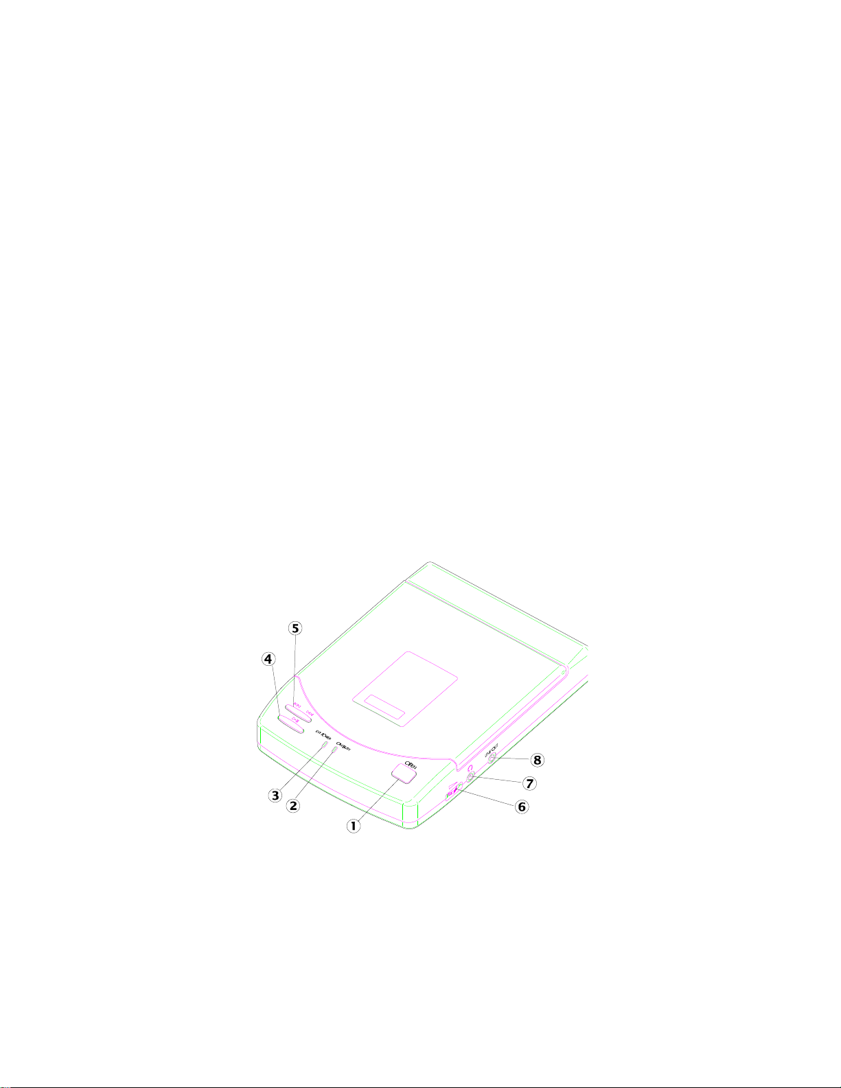
TOP PANEL OF THE CD-ROM DRIVE:
•• Open button:
Press this button to open the disc cover.
‚‚ On/Busy led:
• This indicator will light dimly with a green LED when the power is on.
• This LED will light brightly when the drive is ready.
• This LED will blink when the drive is accessing the disc.
• This LED will blink every 2 seconds when the disc cover is opened.
ƒƒ External Power led:
• This LED will light when AC adapter or batteries are used.
• This LED will blink when input power is low.
„„ Play/Pause button: (for CD audio operation only)
• When the drive is in ‘stop’ state, pressing this button will activate the
drive to start playing.
• When the drive is in ‘play’ state, pressing this button will make it pause.
Figure 1
…… Next/Previous button: (for CD audio operation only)
- -
5
Page 6
• When the drive is in ‘play’ state, pressing the right edge of the button
will skip to the next track.
• When the drive is in ‘play’ state, pressing the left edge of the button will
skip to the previous track.
†† Headphone Volume Control knob:
Turn this rotary knob to adjust the headphone volume.
‡‡ Headphone jack:
This is a 3.5mm audio headphone jack.
ˆˆ Line-out jack:
Audio outputs signal to an amplifier.
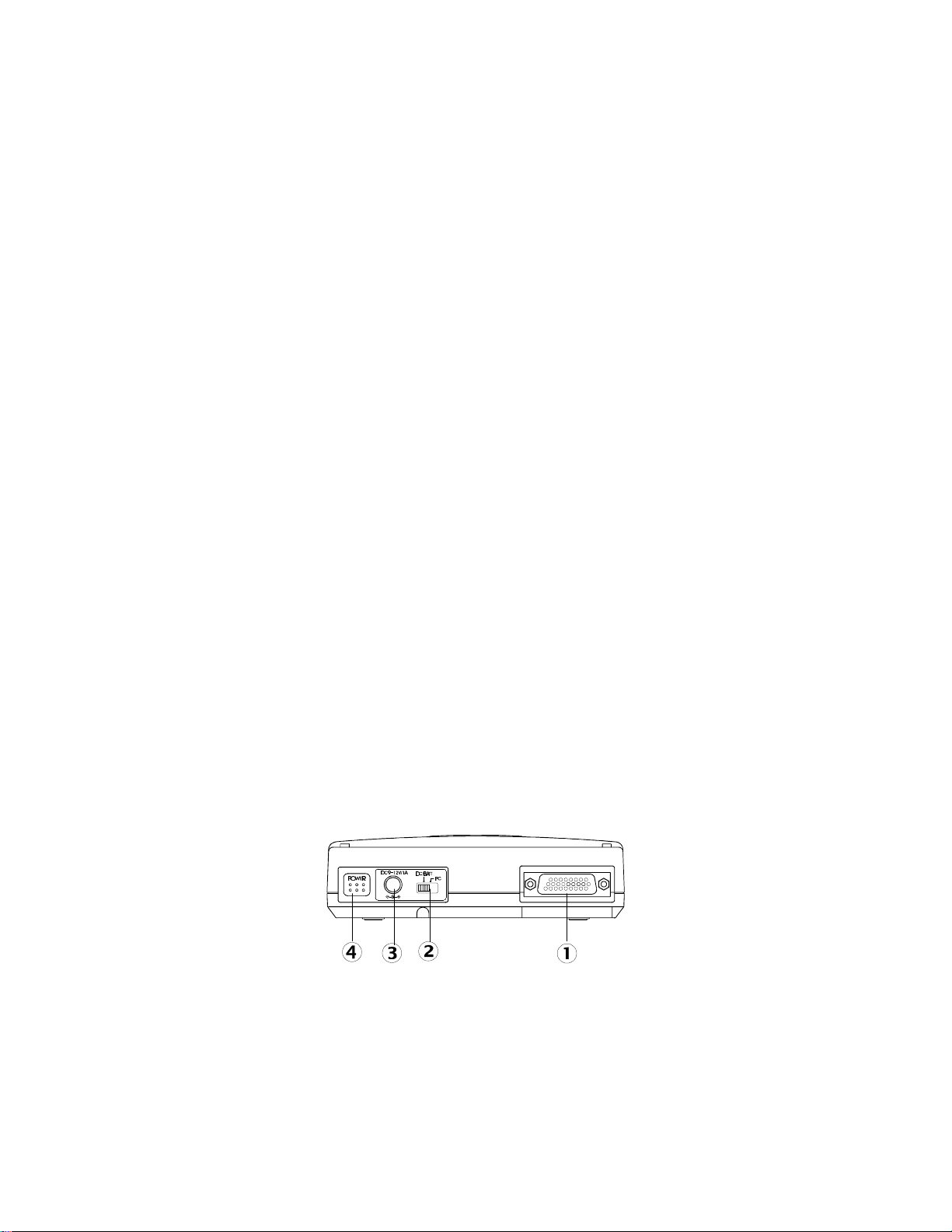
REAR PANEL OF THE CD-ROM DRIVE:
•• PCMCIA/Parallel Port Interface connector:
This connector connects to the PCMCIA interface card or the Parallel
Port interface cable.
‚‚ Power Source switch:
• Set the switch to “PC” to select the power source from PCMCIA socket.
• Set the switch to “DC/BATT” to select the power source from AC
adapter or batteries.
Please refer to next section titled “CD-ROM POWER SOURCE” for
details.
ƒƒ DC-IN jack:
This jack connects to an AC adapter.
„„ Power button: (for stand-alone CD player operation only)
Press this button to power on/off the drive when it is used stand-alone as
an audio CD player.
Figure 2
- -
6
Page 7
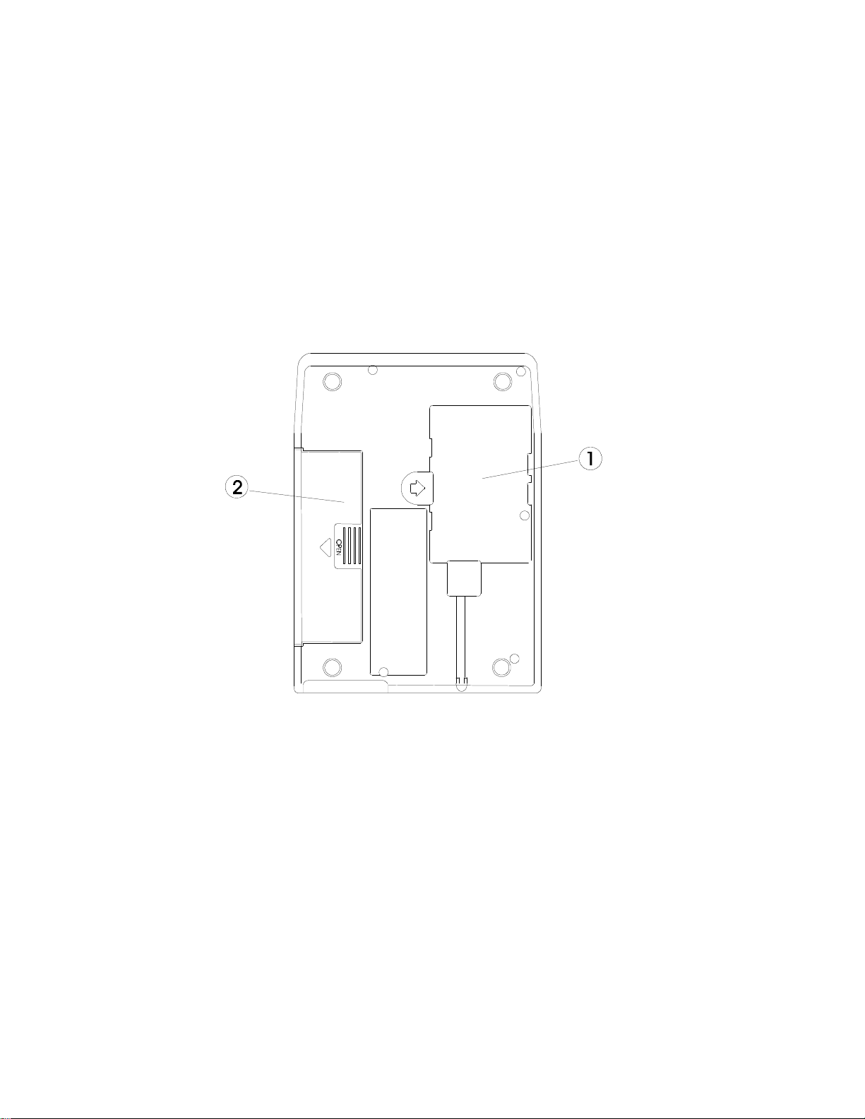
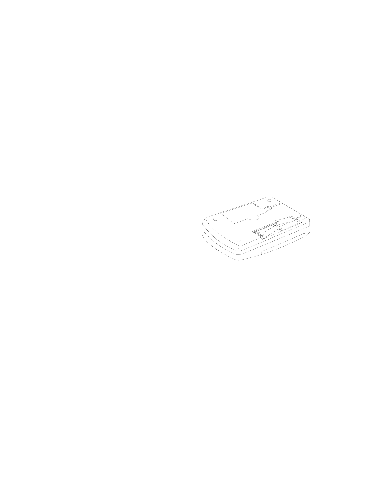
BOTTOM OF THE CD-ROM DRIVE:
•• PCMCIA Interface Card Holder:
Store the PCMCIA interface card when not used.
‚‚ Battery Lid:
Slide and lift up the lid to install or remove the batteries.
Figure 3
- -
7
Page 8
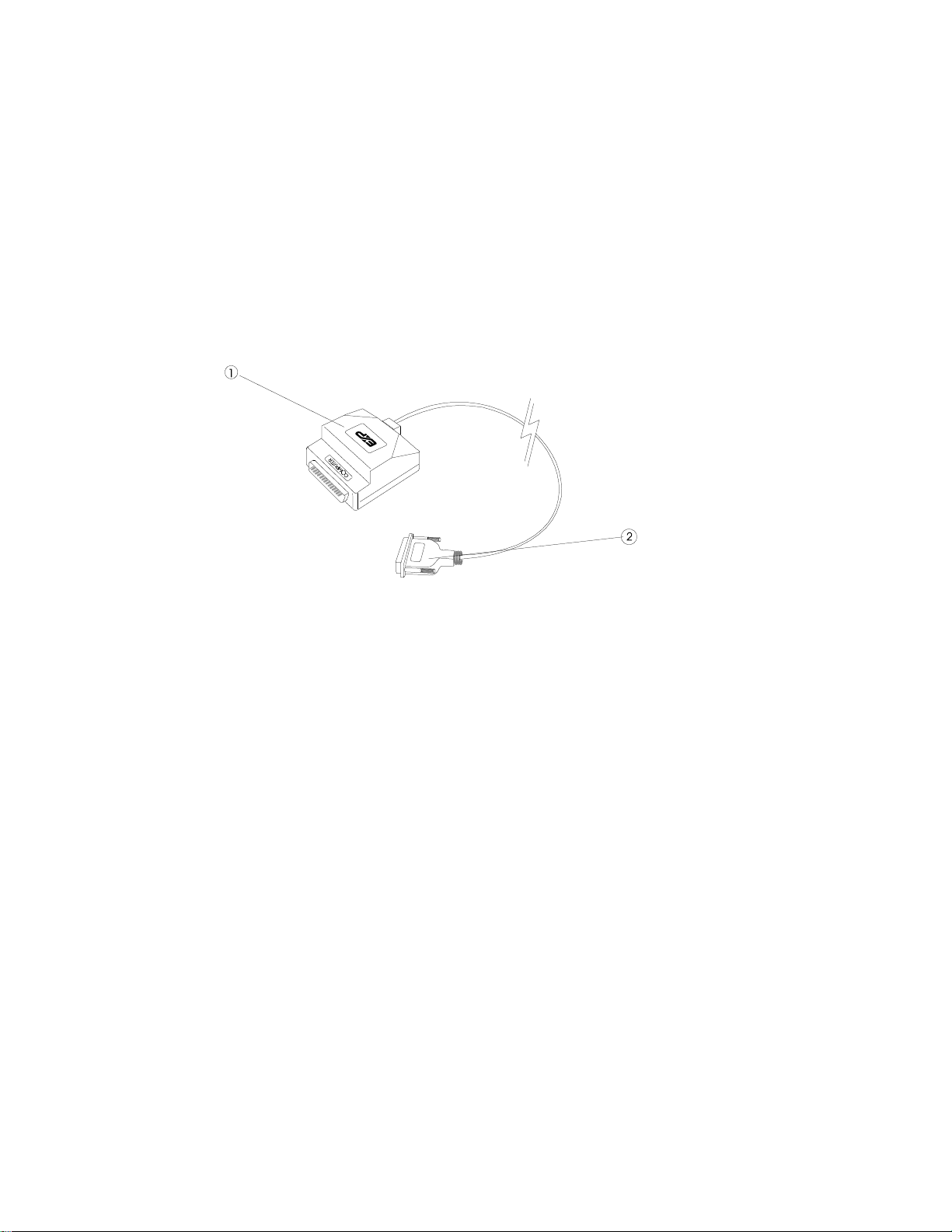
PARALLEL PORT ADAPTER CABLE:
•• Parallel port connector:
Connect this connector to a computer (25 pin) parallel port (Printer port).
‚‚ CD-ROM drive connector:
Connect this connector to the back of CD-ROM drive (26 pin)
Figure 4
CD-ROM POWER
There are three power source options to choose to power the CD Traveler:
1. PCMCIA socket power direct
2. AC adapter
3. Battery.
However, you can use only AC adapter or batteries when the CD-ROM is
used with the Parallel Port connection or as a stand-alone CD player.
SELECTING THE POWER SOURCE
The POWER SOURCE SWITCH (as shown in ‚ of Figure 2) is for selecting
which power source to use.
PC Card (PCMCIA) interface
User can select power source form PC or DC/BATT.
Parallel Port interface
User selects power source from DC/BATT only.
- -
8
Page 9
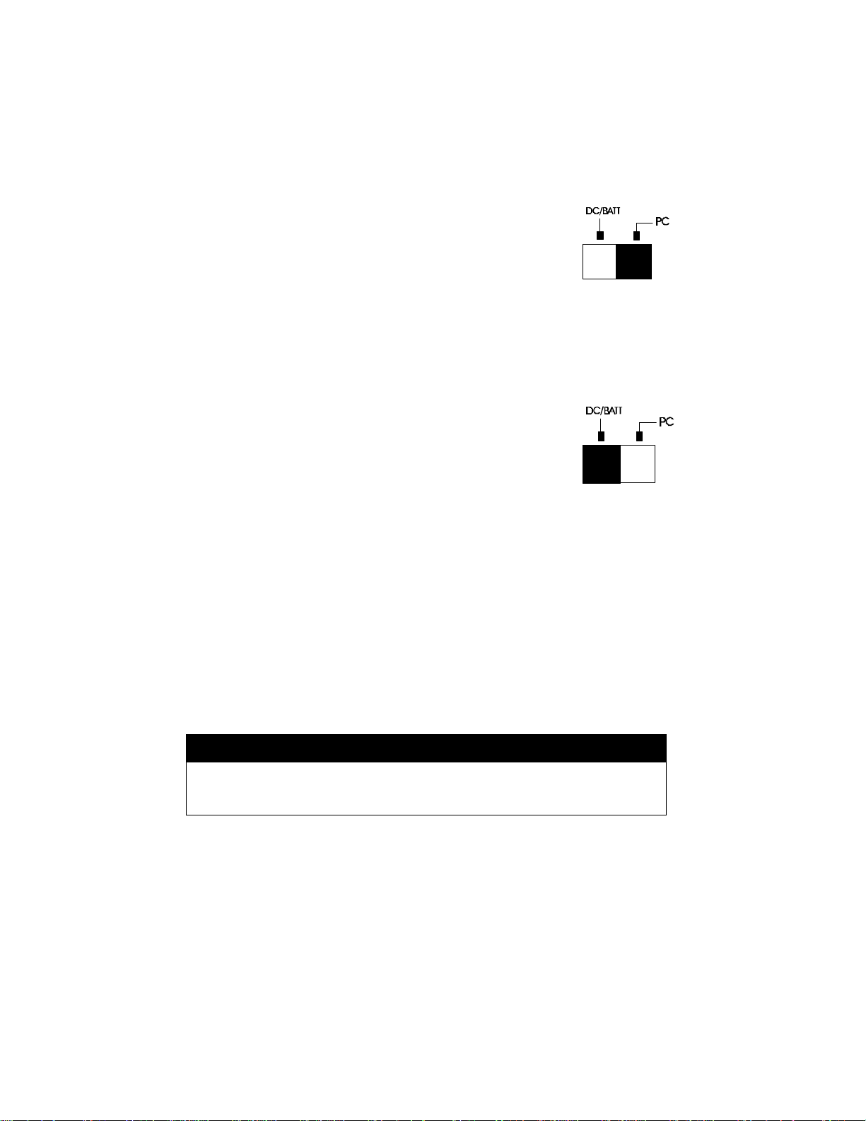
POWER SOURCE SWITCH is set to “PC” (Figure 4.a)
The PCMCIA power direct is selected. Thus, the CD-ROM
will obtain power from PCMCIA socket of your computer,
there for no external power (AC or batteries) will be required.
In the event that your computer can not supply enough power
Fig. 4.a to operate the PCMCIA CD-ROM drive, then you will have to use
external power as described below. Do not set the switch to this position if
you are using the Parallel Port connection.
POWER SOURCE SWITCH is set to “DC/BATT” (Figure 4.b)
The external power source is selected. In this condition, you
must apply AC adapter or batteries to CD-ROM drive. The
Parallel Port connection requires the switch setting in DC/Batt
position. Please note that the AC adapter has a priority over
the battery in powering the CD-ROM drive. In other words, if
you connect the AC adapter, the CD-ROM drive will draw power Fig.4.b
from the adapter regardless if the batteries are installed or not.
NOTE: If you choose to use external power, remember to apply external
power before enabling the PCMCIA interface card (booting the
computer or hot-inserting the card).
For the Parallel Port connection, user will also need to apply external
power before booting the computer.
If you failed to apply the external power first, the drive status will
remain NOT READY although the external power is applied later; it
may also result in CD-ROM drive abnormal condition. In this case,
reboot your computer again to enable the CD-ROM drive.
WARNING
Do not shift the POWER SOURCE SWITCH when the CD-ROM is
powered on.
- -
9
Page 10
CONNECTING THE AC ADAPTER
1. Remove the PCMCIA interface card or Parallel Port connector from your
computer.
2. Connect the AC adapter plug to the DC-IN jack at the CD-ROM rear
panel.
3. Attach the AC adapter to the AC outlet.
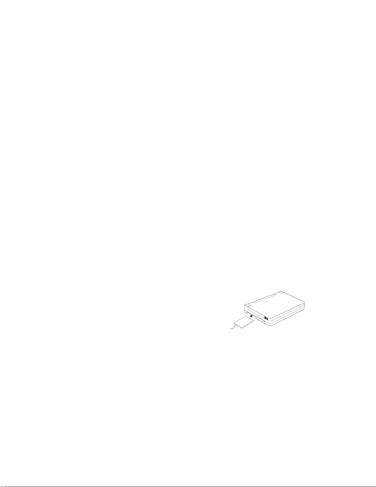
INSTALLING THE BATTERIES
The CD-ROM requires six AA size batteries (not included) for operation. The
Alkaline batteries may last longer than other batteries. You may also use NiCad rechargeable batteries, which have a shorter service life. Neither the
rechargeable batteries nor the charger is provided with this package.
Follow the instruction below to install the
batteries,
1. Remove the disc from the CD-ROM.
2. Disconnect the PCMCIA interface card
from your computer, and disconnect the
AC adapter from the “DC-IN” jack.
3. Turn over the CD-ROM drive and place
it horizontally.
4. Press and slide the battery lid in the
direction of the arrow to remove it. Figure 5
5. Install six fresh AA batteries (as shown in Figure 5), and make sure the
polarities match the diagram.
6. Replace the battery lid.
- -
10
Page 11

POWER SWITCH
Stand-alone CD player
Pressing the POWER button (as shown in „ of Figure 2) will switch the CD
drive power ‘on’ or ‘off’. The drive also has an inactivity timer, which
automatically powered off if it has been idle more than 40 seconds.
CD-ROM operation
The POWER button will not function because the drive power is controlled by
the computer.
ON/BUSY LED (as shown in ‚ of Figure 1)
The LED indicate four status of the CD-Drive:
1. Power On: The LED will light dimly
2. Ready State: The LED will light brightly.
3. Accessing: The LED will blink when the drive is accessing the disc.
4. Cover Open: The LED will blink every 2 seconds.
EXT POWER LED (as shown in ƒ of Figure 1)
The LED indicates the external power state:
1. ON: The power supply is in the normal condition.
2. OFF: If you choose to use PCMCIA power direct.
3. BLINKING: External power is in use but power is low.
Low power may be caused by a malfunction AC adapter or when the
batteries are reaching the end of their service life. Check your AC adapter
to see if it is defective, improperly connected, or replace the old batteries
with new ones.
NOTICE
• Use only the AC adapter provided with this unit or refer to the rear panel
of the drive for the correct AC adapter specification.
• If you are not using the unit with the AC adapter for a long period of time,
disconnect it from the AC power outlet.
• Do not mix old and new batteries, or different type of batteries (Ni-Cad
and alkaline, etc.)
- -
11
Page 12

• Always remove old, weak or worn-out batteries promptly and dispose of
them properly.
• If you do not use this unit for a long period of time, remove the batteries
to avoid the possible battery leakage.
• Thoroughly clean the battery compartment before inserting new batteries.
• Always turn on the CD-ROM power before the system if using the AC or
batteries
- -
12
Page 13
INSTALLATION
The installation procedures have two sections for each type of interface.
1. PCMCIA(PC Card) interface
2. Parallel Port interface (option)
The procedure includes hardware and software installation. Just follow along
the interface of your choice.
INSTALLATION FOR PCMCIA INTERFACE
HARDWARE INSTALLATION
If install on a Windows NT station, make sure you turn OFF all power to your
system before connecting the CD Traveler Plus to your computer. However,
you are allowed to install the CD with power while using Windows 95/98,
because OS support plug-and-play. Before you begin, make sure you turn
OFF all power to your system before connecting the PCMCIA CD-ROM to
your computer.
1. Turn over the CD-ROM drive, locate the PCMCIA interface card at the
back of the CD-ROM drive. Lift and take out the card from the holder.
Place the CD-ROM drive upright in the horizontal position.
2. Make sure that the PCMCIA interface cable is firmly connected to the
interface connector at the back panel of the CD-ROM drive.
3. Refer to the computer user’s manual to locate your computer’s PCMCIA
slot.
4. Align the PCMCIA interface card with the arrow
sign pointing towards the computer’s slot.
(Please note that the card is keyed to guide for
proper insertion.)
5. Slowly insert the PCMCIA interface card into the
slot and press firmly until the connector is seated.
6. Check the power source switch set it according to power source and your
connection type.(PCMCIA or Parallel Port)
PCMCIA Socket -> PC
AC adapter or Battery -> DC/BATT (Parallel Port only)
(Make sure the AC adapter is properly connected or the batteries are
installed)
7. Turn the system ON to install the PCMCIA CD-ROM device driver.
- -
13
Page 14

SOFTWARE INSTALLATION
SOFTWARE INSTALLATION FOR WINDOWS 95/98
The “New Hardware Found” dialog box* will appear when you insert the CD
CD Traveler Plus card under Windows 95 for the very first time.
Select “Driver from disk provided by hardware manufacturer” and click on the
OK button. Insert the CD Traveler Plus device driver disk into your floppy
drive. (If the dialog box does not appear, please refer to the “Trouble Shooting” section.)
Either using “Browse” button or types in the path A:\win95 then click OK to
finishing the installation.
* Your dialog box may be different from the one shown depending on your Windows 95 version
- -
14
Page 15

For user with a newer revision of Windows 95 or Windows 98, “Update
Device Driver Wizard” box * will appear. Click on “Next” button, let Windows
95 search for driver. Make sure to insert the CD device driver diskette into
your floppy drive.
(If the dialog box does not appear, please refer to the “Trouble Shooting” section.)
Click on the “Finish”
button.
VERIFY YOUR INSTALLATION
From “Desk Top” click on “My Computer” icon.
Look for an addition CD-ROM drive’s icon.
- -
15
Page 16

SOFTWARE INSTALLATION FOR WINDOWS NT 4.0
PC CARD Interface
Currently there is no Plug and Play support for PC Card (PCMCIA) on the
Windows NT 4.0. User can install the device driver without the PC Card,
however after you finishing the installation you should insert the PC Card
before restart the computer.
Follow the instructions to install the device driver:
Click on My Computer, then “Control Panel”, then “SCSI Adapters”.
Choose Drivers tab and the click on “Add”. From the Install Driver click “Have
- -
16
Page 17

Disk” button.
Install from disk dialog box will prompt for device driver diskette.
Either using “Browse” button or type in the path A:\winnt the click OK to
finishing the installation.
Make sure to insert the CD PC Card into the PC Card slot before restart the
computer.
VERIFY YOUR INSTALLATION
After computer boot up from “Desk Top” click on
“My Computer” icon. You should have an addition
CD-ROM icon.
- -
17
Page 18

INSTALLATION FOR PARALLEL PORT INTERFACE
HARDWARE INSTALLATION
Before you begin, make sure you turn OFF all power to your system before
connecting the CD-ROM to your computer.
1. Connect the DC Input adapter cable to the EXP CD-ROM drive
assembly.
2. Connect one end of the Parallel cable to EXP CD-ROM (26 pin small
connector), and connect the other end to computer parallel port.
(standard 25 connector)
3. Plug-in the AC adapter to a working AC receptacle.
4. Turn on the power of CD-ROM before turn on the computer.
You are now ready to install the software.
WARNING
The CD and electronic components installed on the CD-ROM are very sensitive
to damage from static electricity. Before handling the unit, touch a grounded
metal surface. DO NOT connect/disconnect the CD-ROM unit to/from the
parallel cable when the system is in power-on state.
SOFTWARE INSTALLATION FOR WINDOWS 95/98
From the Desktop Click ‘My Computer’ icon, ‘Control Panel’ and then ‘Add
New Hardware’ Click "Next>" to begin.
1. When prompted whether to search for your new hardware,
- -
18
Page 19

Select "No" and click "Next>".
2. Open "SCSI controllers". Click "Have Disk...".
3. Insert Installation Diskette into the drive selected, then click "OK".
4. If you're installing from a directory containing downloaded installation
files, specify the full path of the directory and click "OK".
5. Select "PHT Parallel-Port PHT-Series Win95 Driver",
and click "Next>". Click "Finish" to complete installation.
6. Remove Installation diskette.
- -
19
Page 20

7. Restart system, when prompted.
VERIFY YOUR INSTALLATION
From “desk top” click on “my computer” icon. There should be addition CDROM drive’s icon displayed.
- -
20
Page 21

SOFTWARE INSTALLATION FOR WINDOWS NT 4.0
In Windows NT 4.0, you may select “Control Panel” under “Settings” from the
“Start” menu to open the “Control Panel” folder, double click the “SCSI
Adapter” icon)
Click “Drivers” tab, and a figure illustrated as below will be displayed.
Click “Add” button, and click “Have Disk...” button.
Windows NT will then prompt you to insert the manufacturer installation disk.
Insert the device driver disk into your floppy drive. Specify the directory as
A:\WINNT (or B:\WINNT whichever contains the diskette) and select OK.
- -
21
Page 22

Click OK to select the driver.
Follow the on-screen instruction to continue. After finishing, Windows NT will
prompt you to restart your computer to activate the new device driver for
Windows NT.
- -
22
Page 23

BASIC OPERATING PROCEDURES
Follow the instructions listed below to open the disc cover and insert/remove
a CD.
Press the OPEN button. The disc cover will open slightly, and the ON/BUSY
LED will blink as a warning signal.
Figure 6
If there is no disc inside, go to next step. Otherwise, wait until the drive stops
spinning. You may check if the disc stop by looking through the disc cover
window.
Lift the disc cover by the edges as shown in Figure 6.
Insert the disc with the label side facing up or remove the disc.
Close the disc cover.
WARNING
Do not lift the disc cover until the drives stop spinning. Failure to
do so may damage the CD disc.
- -
23
Page 24

INSTALLING THE APPLICATION SOFTWARE
Windows 95/98 and Windows NT 4.0
From “Start” go to “Setting”, “ Control Panel” then “Add/Remove Program”
Click on “Install” button. The installation program will search for ‘Setup.exe’
program from the CD-ROM. Usually the application will start automatically.
If not click “Browse” button then open the sub-folder contain the setup
program.
Follow your application program instructions.
USING THE CD-ROM AS A STAND-ALONE CD PLAYER
In a stand-alone audio CD player operation, the CD need either the AC
adapter or batteries for its power source remember to set the POWER
SOURCE SWITCH to “DC/BATT”. Refer to the section titled “CD-ROM
POWER SOURCE” for details.
- -
24
Page 25

It is not necessary to remove the PCMCIA interface card from the CD-ROM
drive when the CD-ROM is in stand-alone mode. You may store the card in
the cardholder at the back panel of the drive.
The following control buttons will be used in stand-alone mode.
Power Button
• Press the POWER button will turn on the PCMCIA CD-ROM in stand-alone
mode. Press the POWER button again will turn off the drive.
• The PCMCIA CD-ROM will spin in a lower speed (single speed) in stand-
alone mode.
• As another power saving feature, the PCMCIA CD-ROM will be
automatically turned off if it has not played for approximately 40 seconds.
Play/Pause Button
• Press this button will activate the drive to begin playing.
• If the drive is in play state, pressing this button will make it pause.
• This button will work in the audio CD playing mode only..
Next/Previous Button
• In the play state, press the right edge of the button to skip to the next track.
• Press the left edge of the button to skip to the previous track.
• This button will work in the audio CD playing mode only..
Volume Control Knob
• Use this knob to adjust the headphone volume.
- -
25
Page 26

Headphone Jack
• Connect your headphone to his jack for listening to audio CD.
Line-Out Jack
• Connect this jack to the LINE-IN jack of the sound card in your computer or an
amplifier with a 3.5 mm audio cable for better sound quality from the audio CD.
Play an Audio CD by Using Software
You can use the CD audio software utilities in Windows 95 or Windows NT
Windows 3.1 etc. to play the audio CD on your CD-ROM.
Windows 95/98 and Windows NT incorporate an auto-run function for a CD
Audio disk. As soon as you insert the CD inside the drive the computer will
automatically start, a program called CD-Player. You should see number
incrementing. If not, you should go to Start, Program, Accessories,
Entertainment, and choose CD-Player or Media Player. Press Play button to
start. To play audio CD by using Media Player in Windows 3.1, for example,
1) Check if the [MCI] CD Audio driver is installed.
2) Choose the Drivers icon from Control Panel, and choose the Add button
to set up the driver [MCI] CD Audio.
3) Start the Media Player.
4) Select Device CD Audio from the menu bar.
5) Click the play button on the screen to start it.
- -
26
Page 27

If your computer is equipped with a sound card, you can also connect the
LINE-OUT jack of your CD-ROM to the LINE-IN jack of the sound card with a
3.5 mm audio cable. This will result in a better audio output from the
speakers of the sound card.
The CD-Audio sound will come out through the Line-Out or Headphone
jack ONLY.
The PLAY/PAUSE, NEXT/PREVIOUS buttons will still work in CD-ROM
mode. However, these buttons should be used in audio CDs playing mode
ONLY. Using these buttons other than playing audio CDs will cause an error.
Also, do use these buttons along with a CD audio software utility. Otherwise,
incorrect information may be reported by the CD audio software.
- -
27
Page 28

TROUBLE SHOOTING
PCMCIA INTERFACE
Symptom: No “New Hardware Found” dialog box display.
Solution: 1. The EXP card is NOT fully inserted.
The card status will show empty if Windows PCMCIA driver did
not detect any card. Some time, there is other dialog box
displayed, and the PC Card Properties still show empty. You
may need to disable such a program (i.e. CardWork, CardWiz)
consult your notebook User Manual.
2. The 32-bit card support is NOT enabled.
To enable the 32-bit support, click on “Start”, “Settings”,
“Control Panel” from the “Control Panel” folder Click on PC
Card (PCMCIA)
- -
28
Page 29
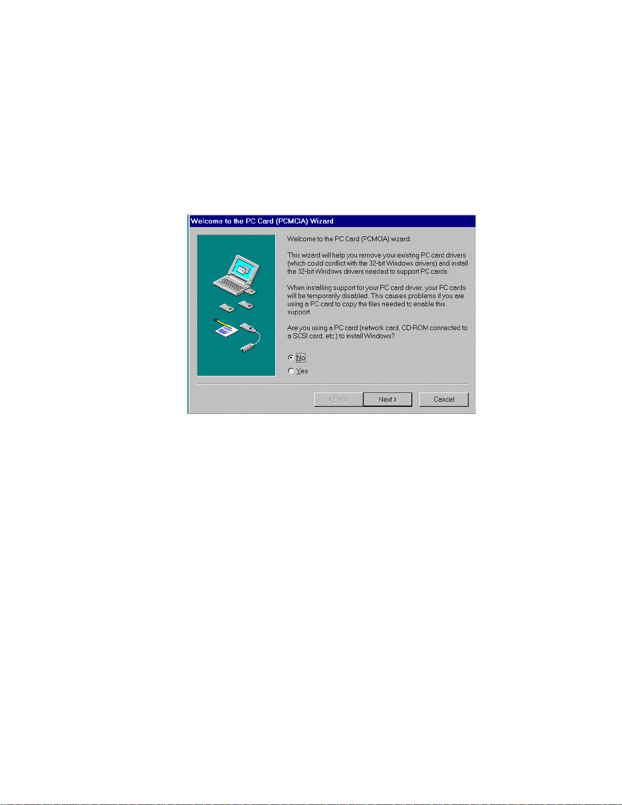
If you see the screen below, it means the PCMCIA device driver
is not using 32-Bit Card Support. Follow on screen instructions by
except all the default setting. At the end of the installation, you
will be asked to restart the computer.
After the computer restart, you can insert the EXP CD card, at
this time the “New Hardware Found” or “Update Device Driver
Wizard” dialog box will be displayed.
3. No PC Card (PCMCIA) icon in Control Panel
If the PCMCIA Socket is not found, then you must add a
PCMCIA socket to your system. Please click on the “Add New
Hardware” icon in the Control Panel folder and select “PCMCIA
socket”. Select the appropriate type of PCMCIA Controller that
matches yours (call your notebook manufacturer for detail) and
follow the on-screen instruction.
Symptom: No additional drive icon in “My Computer”.
The EXP CD driver installed without any incident.
Solution: 1. System resources for the EXP CD are not available.
Click on “Start”, “Settings”, “Control Panel” from the “Control
Panel” folder Click on “System” then “Device Manager”
- -
29
Page 30

The EXP entry may
have a yellow circle
with an exclamation
point.
This is an indication
that the EXP CD did
not working properly.
Double click on EXP entry line and then select “Resources” You
can make some
change to the
following entry:
‘Basic Configuration
xxxx’, I/O Range,
and Interrupt
request.
During resources
changing, observe
the “Conflicting
Device List”. You
should select the
resource(s), which
the “Conflicting
device list” shows
“No Conflict ”
- -
30
Page 31

2. Device Manager shows resource for the EXP CD is available and
there is no conflicting device.
In some computer, the I/O Range XXX, Interrupt Request 15
may be use by a built-in secondary IDE controller. Try changing
the interrupt to 9,10 or 11. You can also try different I/O
addresses.
3. The EXP entry may have a yellow circle with an exclamation
point. Device Manager shows resource for the EXP CD is
available and there is no conflicting device.
Check all connection to the EXP CD drive assembly, such as AC
Adapter. Your notebook PC Card sockets may not have enough
power for the EXP CD. If you already connect the AC adapter,
make sure to secure all connectors and the adapter plug into a
good AC out let.
4. The EXP CD and the ‘Standard IDE/ESDI Hard Disk Controller’
entry have a yellow circle with an exclamation point.
Your notebook may have been infected with some kind of
computer virus. The virus disabled Windows 95 32-bit device
driver for the hard disk. The EXP CD requires the driver for its
operation. Check the “Performance” tab to confirm the symptom.
You need to run an anti-virus program first, once the 32-bit driver
is running the EXP CD will be installed.
- -
31
Page 32

PARALLEL PORT INTERFACE
Symptom: No additional drive icon in “My Computer”. The EXP CD driver
installed without any incident.
Solution:
1. Check your cable connection, along with the AC adapter at the
wall receptacle make sure there is no lose connection. The
green LED on the front of EXP CD assembly should lit up.
2. Check your computer CMOS or BIOS setup. Some computer
allows user to set printer type to be: Standard, EPP Only or Bidirectional. A setting to “EPP Only” is preferred for a better
performance.
3. Check if other hardware devices are connected to the same
parallel port. Daisy-chaining with other hardware devices is NOT
recommended. Other devices include but not limited to the
following: security device (key, lock), audio port, parallel-to SCSI
device, tape backup device, network device, A/B switch, printersharing device.
4. If you connect the equipment in daisy-chain fashion, always turn
on the device farthest away from the computer first (in this case
the EXP CD), then turn on the device next on the chain. Turn
the computer last.
5. Make sure you turn on the CD-ROM power before the system,
Symptom: The EXP CD starts to become excessively slow or behave
differently on a battery-powered notebook computer.
Solution: If you are using a notebook or laptop computer, without the AC
adapter. The performance of the parallel port may become
sluggish and unreliable if the battery runs low. Try reconnecting
the AC adapter to your computer or recharging the battery.
Symptom: The EXP CD starts to become excessively slow or does not
work at all.
Solution: The parallel port on your machine may be able to a number of
different modes, standard, Bi-directional, EPP or ECP. These
- -
32
Page 33

different setting can effect performance of the EXP CD. In some
cases, the standard setting will even shut off signals the EXP
CD needs, while if the same port is set to Bi-directional or EPP
produce an excellent performance.
- -
33
Page 34

REMOVING OR RE-INSTALLING THE DRIVER
PCMCIA INTERFACE
If you need to remove or reinstalling the driver, make sure the EXP CD-
ROM disk card is inserted.
• Go to “My Computer” icon, “Control Panel”, “System”,“ Device
Manager” Click on “Hard Disk Controller”. The EXP CD should be
listed
To remove EXP CD-ROM.
• Click on the EXP entry line then click “Remove” button. You may
need to restart the computer to complete the task.
To reinstall EXP CD-ROM.
• Click on “Refresh” button, either the “New Hardware Found”
- -
34
Page 35

or “Update Device Driver Wizard” will be displayed.
Follow the instruction on “Installation for PCMCIA Interface” section.
PARALLEL PORT INTERFACE
Go to “My Computer” icon, “Control Panel”, “System”,“ Device Manager” Click
on “SCSI Controller ”. The EXP CD should be listed
To remove EXP CD-ROM.
• Click on the EXP entry line (F.I.T. …) then click “Remove” button.
You may need to restart the computer to complete the task.
To reinstall EXP CD-ROM.
• Click on “Refresh” button, either the “New Hardware Found”or
“Update Device Driver Wizard” will be displayed.
Follow the instruction on Installation for “Parallel Port Interface” section.
- -
35
Page 36

INSTALL A CD TITLE
DOS/Windows 3.x
Most of the CD-ROM titles for Windows 3.1/3.11 contain the SETUP.EXE or
INSTALL.EXE program in the CD disc. You need to start either one of the
programs to add a Program Group and its icons into your computer, and
perform the following,
1) In Program Manager click File => Run
2) Type in D: (or the drive letter assigned for CD-ROM) SETUP.EXE or
INSTALL.EXE.
3) Follow the on-screen instructions.
4) After setup is completed, click the program icon to start the program.
Windows 95/98 and Windows NT 4.0
The CD-ROM for the Windows 95 titles include the AUTO RUN feature. This
means that when you close the disc cover with this type of CD disc inside,
Windows 95 will start the opening screen automatically. You can add the
program, browse content of the CD, etc. from this screen.
The other procedure is from ‘Control Panel’ click on ‘Add/Remove Programs’
icon, click on ‘Install’ button then follow the on screen instruction.
Hot Insert/Remove the PCMCIA interface card
The PCMCIA interface specification define that you may hot insert/remove
the PCMCIA interface card, which means to insert, remove or exchange the
card from your system at any time without rebooting or turning off your
system.
However, for any given system, the PCMCIA CD-ROM, being a storage
device itself, can not be hot removed when it is in use by a program. To avoid
some sort of system failure, read the following carefully before using hotremoving technology.
DOS/Windows 3.X
The hot insert/remove the PCMCIA CD-ROM function is supported ONLY
when your computer is loaded with PCMCIA software which is ExCA
compliant. If your system doesn’t have such software, it is necessary to
connect the PCMCIA CD-ROM first before your computer is being booted. Do
not hot remove the card when the CD-ROM is accessing the data particularly
in OS/2 system.
- -
36
Page 37

Windows 95
The hot swapping is allowed with more limitation. To avoid system failure,
always follow the below steps to hot remove the PCMCIA CD-ROM in
Windows 95,
1) Click the PC card indicator on the task bar at the right bottom of screen.
2) Click the command to stop the card you want to remove.
3) Read the screen prompts instruction carefully. If the system prompts you
not to remove the card, DO NOT remove the card. You should exit the
present application and return to step 1.
Be sure you are removing the card by the procedures described above,
otherwise, the following dialog will be displayed:
To display the PC card indicator on the task bar, perform the following steps,
1. Double-click the PC Card (PCMCIA) icon in the Control Panel.
2. Make sure that the box ‘Show the control on task bar’ is checked.
If the PC Card (PCMCIA) wizard appears when you click the button in step 1,
complete the wizard. After restarting your computer, double-click the PC Card
(PCMCIA) icon in the Control Panel, and then check the box to see the status
indicator on the task bar.
NOTICE
• While operating the CD-ROM, the speed of your computer’s CPU and
display card will dominate the overall performance, especially when
playing full motion video. Slow display speed often causes “still frames”.
• To play the sound portion of Multimedia CD Titles, your computer must
be equipped with a sound card.
- -
37
Page 38

APPENDIX A
DEVICE DRIVER INSTALLATION FOR DOS
PCMCIA Interface
Automatic Installation
The INSTALL program helps you install the device driver into your computer
easily. Please follow the instructions below to proceed with automatic
installation.
1. Insert the device driver diskette into a floppy disk drive on your computer.
2. Change the working directory to the floppy drive containing the device
driver diskette by typing “A:” or “B:” then press ENTER.
3. At the DOS prompt (A:\> or B:\>), type “INSTALL” followed by the ENTER
key.
4. Press ENTER or click on the OK button to continue. When the opening
screen appears, a dialog box will be displayed for you to specify the
necessary parameters:
• Directory to install the device driver.
• The DOS directory to specify the location of the MSCDEX driver.
• The I/O port address
• The IRQ number.
5. Enter the directory you select to install the driver and press the TAB key to
forward to the next field to indicate the DOS Directory. Press the TAB key
again to set the I/O port and then the IRQ. The default setting of the I/O
ports are (170-177, 376-377), and the default IRQ is 15.
6. After completing the selection, click on the Install button to continue.
7. The rest of the installation should proceed automatically, and the
CONFIG.SYS and AUTOEXEC.BAT files on your computer will be
updated.
8. Reboot your computer and the CD-ROM drive will be defined as the next
available drive letter. For example, if the last hard drive of the computer is
drive C, the CD-ROM drive will be assigned to be drive D: automatically.
- -
38
Page 39

Manual Installation
You may also manually install the Portable CD-ROM device driver if the
default setting conflicts with your system. Please follow procedures below to
complete this manual installation.
1. Copy the files EXPCDI.EXE from the Portable CD-ROM device driver disk
to your hard disk.
2. Copy or locate the MSCDEX.EXE in your hard disk. Usually reside at
C:\DOS or C:\WINDOWS\COMMAND
3. Add “LASTDRIVE=Z” to the TOP of your CONFIG.SYS file. If you already
have a LASTDRIVE line with a letter other than Z, change it to Z.
4. Add the following lines to the BOTTOM of your CONFIG.SYS file:
DEVICE=drive:\path\EXPCDI.EXE /P:1 /I:15 /D:MSCD001
where drive:\path specifies the directory containing the file EXPCDI.EXE.
Note: If your CONFIG.SYS file is already loaded with PCMCIA software, such
as Cardsoft of SystemSoft or Cardtalk of Databook, it is necessary to add the
above line AFTER all the PCMCIA statements.. Otherwise, the PCMCIA
interface card will not be initialized properly. To make sure if any PCMCIA
software has been loaded in your system and to know more about PCMCIA,
please refer to the section titled “PCMCIA Software Information”.
The EXPCDI.EXE is device driver for the PORTABLE CD-ROM. The
parameters of EXPCDI.EXE are described as below:
/P Set the I/O ports, and the valid numbers are 1, 2, and 3. Each
number represents the I/O port pairs of (170-177, 376-377), (1E81EF, 3EE-3EF), and (168-16F, 36E-36F) respectively. The default
setting is /P:1.
/I Set the IRQ number. The valid IRQs are 3, 4, 5, 7, 9, 10, 11, 12 and
15, and the default setting is /I:15.
/D is used to set the device name. It can be any name up to 8
characters. This name must be the same as the name you will
specify in the MSCDEX.EXE option /D: name in the next step.
5. Add the following line at the TOP of your AUTOEXEC.BAT:
drive:\path\MSCDEX.EXE /D:MSCD001 /M:4
where drive:\path specifies the DOS directory or the directory containing
the file MSCDEX.EXE.
Note: If your AUTOEXEC.BAT file loads a menu program such as
DOSSHELL or Windows, you have to add the above line to start your
menu program. Otherwise, MSCDEX will not have a chance to load
before your menu program begins.
- -
39
Page 40

The example above shows the default setting. The /D: switch indicates
the device name. It MUST be the same name as you specified by the /D:
switch of EXPCDI.EXE in your CONFIG.SYS file. The /M: switch
indicates how much memory to allocate for caching information on the
CD-ROM. The default /M:4 caches 8KB.
For more information about the switches of MSCDEX, please type “help
MSCDEX” at the DOS prompt.
5. Now, reboot your computer to activate the CD-ROM drive.
PARALLEL PORT Interface
Make sure that your computer has an IBM-compatible parallel
(printer) port and DOS 3.1 or above.
1. Follow the instruction on the HARDWARE INSTALLATION section.
2. Place your installation diskette into the floppy drive. (Open a “DOS
prompt” if you are in the Windows environment.)
If the floppy drive is the A drive, enter a:\tcd
If it is the B drive, enter b:\tcd
3. Perform option 1, "Install", from the Utility Main Menu.
******** CD Utility Main Menu ********
1. Install TransCD Software
2. Un-install TransCD Software
3. Audio CD Utility
4. Print TCD.EXE version number
5. Re-boot system
6. List all TransCD devices
7. List all parallel devices
8. Reset CD-ROM drive
0. Exit
Enter menu selection >> 1
4. Follow the instructions on the screen. For the quickest install, press
ENTER to use drive C, press Y and ENTER to use default, and then
- -
40
Page 41

remove the installation diskette and press Y and ENTER to re-boot the
PC.
Most CD-ROM programs require a minimum of a 286 processor with MSDOS 3.1 or MS-WINDOW 3.1, 640K RAM, and an EGA/VGA video card.
Refer to the side of the CD-ROM package for program requirements, and
enjoy!
Access CD-ROM without Software Installation
(Dynamic loading of the CD driver)
This method of Dynamically Loading the CD driver offers a temporary install
of the CD driver. It will not modify CONFIG.SYS and AUTOEXEC.BAT files.
The driver is loaded dynamically. When the system is shut off, the driver is
gone.
1. Place your CD installation diskette into the floppy drive.
2. Select the floppy drive by typing floppy drive letter. For example: A:
3. At the floppy drive prompt, type TCDGO. This will then install the CD
driver.
POWER SAVING
The PCMCIA CD-ROM is designed to save power:
− Built-in inactivity timer for about 40 seconds in stand-alone mode, the
power will be turned off automatically.
− If install in a computer, the drive will automatically enter the sleep mode
(spindle off) when it has not been accessed for about 1 minute.
− If you remove the Compact Disc (CD) from your CD-ROM drive, the drive
will manually go into the sleep mode.
− During the initials power on, the PCMCIA CD-ROM will spin at a lower
speed to save power. The operating current will then be reduced.
The “Hot insert/remove” feature of a PCMCIA card helps to save power, too.
If Exchangeable Card Architecture (ExCA) compliant PCMCIA software has
been loaded on to your computer, then you can remove the PCMCIA CDROM after the system has been booted, and insert it again when you need to
- -
41
Page 42

use the CD-ROM device. For notebook computer users, removing the card
will preserve power and prolong battery life.
Note: You are allowed to remove and insert the PCMCIA CD-ROM from the
computer at any time. However, DO NOT remove the PCMCIA card
from your CD-ROM drive
- -
42
Page 43

EXP COMPUTER, INC.
EXP MEMORY PRODUCTS.
NON-TRANSFERABLE LIMITED WARRANTY
EXP COMPUTER INC., AND EXP MEMORY PRODUCTS ("EXP") warrants that the CD Traveler
(“products”) manufactured or distributed by EXP to be free from failures due to defects in materials
or workmanship for a full one year from the date of purchase of the products.
This warranty is void if the product is damaged by abnormal or improper use or by accident, abuse or
if any attempt to repair or modify the product without authorization from EXP. Your sales receipt or
invoice, showing the date of purchase and the name of the authorized reseller, is your proof of the
date of purchase. During the warranty period, EXP will at its option, replace or repair, at no charge,
the product that in its opinion is defective.
Before you return the failed products, contact EXP. You will need to obtain a Return Merchandise
Authorization (RMA) number by calling EXP’s Technical Support Department at (516) 496-7629. The
RMA number should be displayed on the outside of the returning package and on the accompanying
packing list. EXP cannot be held responsible for any package returned without the RMA number.
You are responsible for packaging, providing proof of the date of purchase and the shipping cost of the
failed product to EXP Computer, Inc. You are responsible for mailing the warranty registration card.
The warranty claims may not be honored if there is no corresponding registration card on file at EXP.
IN NO EVENT WILL EXP BE LIABLE FOR ANY DIRECT, INDIRECT, SPECIAL, INCIDENTAL OR
CONSEQUENTIAL DAMAGE, INCLUDING LOSS OF PROFIT, LOSS OF SAVINGS; OR ANY OTHER
DAMAGES CAUSED BY PRODUCT OR FAILURE OF THE PRODUCT TO PERFORM.
THIS LIMITATION OF LIABILITY APPLIES EVEN IF EXP HAS BEEN ADVISED OF THE POSSIBILITY OF
SUCH DAMAGES. SOME SATES DO NOT ALLOW THE EXCLUSION OR LIMITATION IN INCIDENTAL
OR CONSEQUENTIAL DAMAGES, SO THE ABOVE EXCLUSION OR LIMITATION MAY NOT APPLY TO
YOU.
EXP WEB SITE: WWW.EXPNET.COM
TECHNICAL SUPPORT: 516-496-7629
TECHNICAL SUPPORT E-MAIL: support@expcomputer.com
- -
43
 Loading...