

OPERATOR'S MANUAL
TM
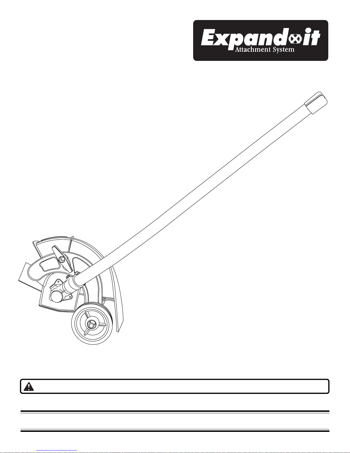
Expand-it™
Edger Attachment
UT15518B
Your new Expand-it™ Edger Attachment has been engineered and manufactured to a high standard for dependability , ease of
operation, and operator safety. Properly cared for, it will giv e you y ears of rugged, trouble-free performance.
WARNING: To reduce the risk of injury, the user must read and understand the operator’s manual.
Thank you again for buying an Expand-it™ Accessory.
SAVE THIS MANUAL FOR FUTURE REFERENCE
TABLE OF CONTENTS
l Introduction ..................................................................................................................................................................2
l Safety Rules.................................................................................................................................................................3
l Symbols .......................................................................................................................................................................4
l Unpacking ....................................................................................................................................................................5
l Features .......................................................................................................................................................................6
l Assembly .....................................................................................................................................................................7
l Operation......................................................................................................................................................................8
l Maintenance ..........................................................................................................................................................9 - 10
l Warranty .....................................................................................................................................................................11
l Parts, Ordering, and Service.......................................................................................................................................12
INTRODUCTION
With the Expand-it™ Edger Attachment you can create a
professionally landscaped look to your lawn. Just connect
the Expand-it™ Edger Attachment to your attachment
capable power head and edging around walkways, curbing,
and other similar areas can be accomplished quickly .
Safety, performance, and dependability hav e been given top
priority in the design of this edger attachment making it
easy to maintain and operate.
WARNING:
Carefully read through this entire operator’s manual
before using your new Expand-it™ Edger Attachment.
Pay close attention to the safety rules, warnings, and
cautions. If you use your tool properly and only for its
intended use, you will enjoy years of safe, reliable
service.
WARNING:
The operation of any tool can result in foreign objects being thrown into your eyes which can
result in severe eye damage. Before beginning tool operation, always wear safety goggles or
safety glasses with side shields and a full face shield when needed. We recommend Wide
Vision Safety Mask for use over eyeglasses or standard safety glasses with side shields.
Always wear eye protection that is marked to comply with ANSI Z87.1.
Look for this symbol to point out important safety
precautions. It means attention!!! Your safety is involved.
2

SAFETY RULES
WARNING:
Read and understand all instructions. Failure to follow
all instructions listed below, may result in electric shock,
fire and/or serious personal injury.
SAVE THESE INSTRUCTIONS
GENERAL SAFETY RULES
l For safe operation, read and understand all instructions
before using the edger attachment. Follow all safety
instructions. Failure to follow all safety instructions listed
below , can result in serious personal injury.
l Do not allow children or untrained individuals to use this
unit.
l Wear safety glasses or goggles that are marked to
comply with ANSI Z87.1 standards and hearing protection when operating this unit.
l Wear heavy long pants, boots, and gloves. Do not wear
loose fitting clothing, short pants, jewelry of any kind, or
go barefoot.
l Secure long hair so it is above shoulder level to prevent
entanglement in any moving parts.
l Keep all bystanders, children, and pets at least 50 ft.
(15 m ) away .
l Do not operate this unit when you are tired, ill, or under
the influence of alcohol, drugs, or medication.
l Do not operate in poor lighting.
l Keep firm footing and balance. Do not o verreach. Over-
reaching can result in loss of balance or exposure to hot
surfaces.
l Keep all parts of your body away from any mo ving part.
l Do not touch areas around the muffler or cylinder of the
power head, these parts get hot from operation. Failure to
do so could result in possible serious personal injury .
l Always stop the engine and remove the spark plug wire
before making any adjustments or repairs except for
carburetor adjustments.
l Inspect unit before each use for loose fasteners, dam-
aged or missing parts. Correct before using the edger
attachment. F ailure to do so can cause serious injury .
l Use only original manufacturer’ s replacement parts.
Failure to do so , may cause poor perf ormance, possible
injury, and will v oid your w arranty.
l Do not, under any circumstance, use any attachment or
accessory on this product, which was not provided with
the product, or identified as appropriate for use with this
product in the Operator’s Manual.
SPECIFIC SAFETY RULES FOR EDGER USE
l Clear the work area before each use. Remove all
objects such as rocks, broken glass, nails, wire, or
string which can be thrown or become entangled in the
edger blade.
l Be sure all guards are properly and securely attached.
l Replace dull or worn blade; do not attempt to sharpen.
l Use this edger for edging along sidewalks, driveways,
flower beds, and similar areas. Do not use for any other
purpose.
l Be thoroughly familiar with the controls. Know how to
stop the unit and disengage the controls quickly.
l Do not use edger in rain or wet locations.
l Do not use the edger on or near graveled surfaces.
l If the edger strikes any type of foreign object:
1. Stop the edger and disconnect the spark plug wire.
2. Inspect for damage to the edger attachment .
3. Correct damage before using the edger attachment.
Failure to do so can cause serious injury.
l Make yourself familiar with the area you are edging. Be
aware of uneven sidewalks, holes in the terrain as well
as other similar hazardous conditions. Always push the
edger attachment slowly over rough ground.
l Always stop the engine and remove the spark plug wire
before installing attachments, or making any adjustments.
3
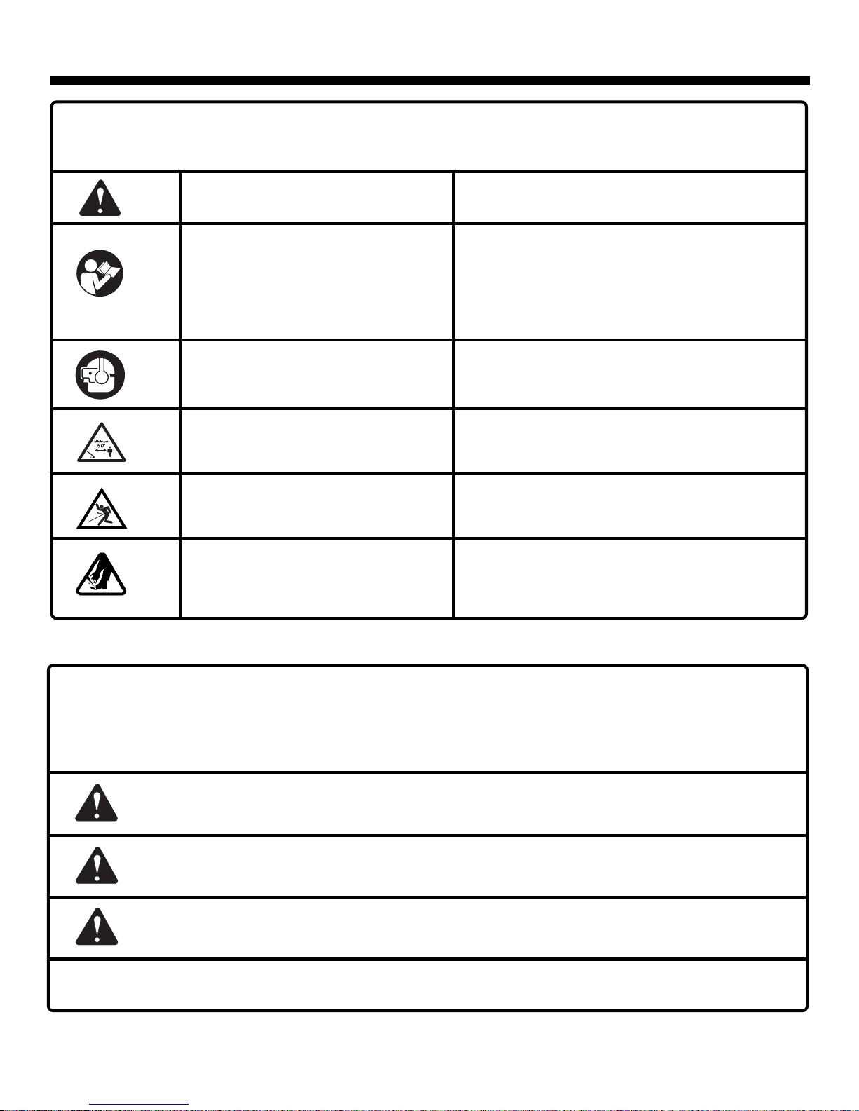
SYMBOLS
Important: Some of the following symbols may be used on your unit. Please study them and learn their meaning.
Proper interpretation of these symbols will allow you to operate the tool better and safer.
SYMBOL NAME EXPLANATION
Safety Alert Symbol Indicates danger, warning or caution. It means
attention!!! Your safety is involved.
Read Your Operator’s Manual Your manual contains special messages to
bring attention to potential safety concerns,
machine damage as well as helpful operating and
servicing information. Please read all the
information carefully to avoid injury and machine
damage.
Wear eye and hearing protection. Wear eye protection which is marked to comply
with ANSI Z87.1 as well as hearing protection
when operating this equipment.
Keep bystanders away. Keep all bystanders at least 50 ft. (15 m)
away.
Ricochet. Danger of Ricochet.
Sharp blade. Danger - Keep hands and feet away from rotating
blade.
The purpose of safety symbols is to attract your attention to possible dangers. The safety symbols, and the explanations
with them, deserve your careful attention and understanding. The safety warnings do not by themselves eliminate any
danger. The instructions or warnings they give are not substitutes for proper accident prevention measures.
SYMBOL MEANING
DANGER: Indicates an imminently hazardous situation which, if not avoided, will result in death or
serious injury.
WARNING: Indicates a potentially hazardous situation which, if not avoided, could result in serious
injury.
CA UTION: Indicates a potentially hazardous situation which, if not avoided, may result in minor or
moderate injury. It may also be used to alert against unsafe practices that may cause property damage.
NOTE: Advises you of information or instructions vital to the operation or maintenance of the equipment.
SAVE THESE INSTRUCTIONS
4

UNPACKING
INSTRUCTIONS
We have shipped the Expand-it™ Edger Attachment
completely assembled.
l Carefully remove the tool from the box. Make sure that
all items listed in the packing list are included.
l Inspect the tool carefully to be sure no breakage or
damage occurred during shipping.
l Do not discard the packing material until you have
carefully inspected and satisfactorily operated the tool.
l If any par ts are damaged or missing, please call
1-800-chainsaw (1-800-242-4672).
PACKING LIST
Expand-it™ Edger Attachment (Completely Assembled)
Hanger Cap
Operator’s Manual
WARNING:
If any parts are missing, replace them before operating
the tool. Failure to do so could result in serious personal
injury.
5

FEATURES
Before using the Expand-it™ Edger Attachment, familiarize
yourself with all operating features and safety requirements.
KNOB
BLADE GUARD
BLADE
WARNING:
Do not allow familiarity with your tool to make you
careless. Remember that a careless fraction of a
second is sufficient to inflict severe injury.
EDGER ATTACHMENT
SHAFT
END CAP
DEBRIS FLAP
GEAR HEAD
WHEEL
Fig. 1
WARNING:
Do not attempt to modify this tool or create accessories not recommended for use with this tool. Any such alteration or
modification is misuse and could result in a hazardous condition leading to possible serious personal injury.
6

ASSEMBLY
The edger attachment is fully assembled at the factory and
requires no further assembly.
JOINING THE POWER HEAD TO THE EDGER
ATTACHMENT
See Figure 2.
WARNING:
Never attach or adjust any attachment while power head is
running. Failure to stop the engine can cause serious
personal injury.
The edger attachment connects to the power head by means
of a coupler device.
1. Loosen the knob on the coupler of the power head shaft
and remove the end cap from the edger shaft.
2. Push in the button located on the edger attachment
shaft. Align the button with the guide recess on the
power head coupler and slide the two shafts together.
Rotate the edger attachment shaft until the button locks
into the positioning hole.
NOTE: If the button does not release completely in the
positioning hole, the shafts are not locked into place.
Slightly rotate from side to side until the button is locked into
place.
3. Tighten the knob securely.
WARNING:
Be certain the knob is fully tightened before operating
equipment; check it periodically for tightness during use
to avoid serious injury.
REMOVING THE ATTACHMENT FROM THE
POWER HEAD
For removing or changing the attachment:
1. Loosen the knob.
2. Push in the button and twist the shafts to remove and
separate ends.
EDGER ATTACHMENT
GUIDE RECESS
POSITIONING
HOLE
POWER HEAD SHAFT
COUPLER
KNOB
Fig. 2
7

OPERATION
WARNING:
Wear safety glasses or goggles when operating this tool.
Failure to do so could result in possible serious injury.
OPERATING THE EDGER
See Figure 3.
Hold the edger with the right hand on the rear handle and
the left hand on the front handle. The edger should be held
on the right side of the body . Keep a firm grip with both
hands while in operation.The edger should be held at a
comfortable position with the rear handle about hip height.
Always operate the unit at full throttle. Prolonged cutting at
partial throttle will result in oil dripping from the muffler.
TO ADJUST THE BLADE DEPTH
See Figures 4 and 5.
Depth of the cut is determined by the distance from the
bottom of the wheel to the tip of blade.
1. Stop the engine and disconnect the spark plug wire.
2. Loosen the adjusting knob and move the wheel arm up
to increase the depth and down to decrease the depth.
3. After adjustment is complete, tighten the adjusting knob
securely.
NOTE: Adjust the blade depth from 1/2 in. to 1 in. (1.2 to
2.5 cm) deep initially. Mak e a shallow cut to test the cutting
depth. If the cutting depth needs adjusting, this should be
done progressively until the desired depth is reached.
ADJUSTING
KNOB
TO INCREASE
DEPTH
Fig. 3
CUTTING TIPS
l The edger will edge along sidewalks, driveways, flower
beds, curbs, and similar areas.
l Use the arrow guide on the blade guard to align the
blade with the edging surface.
l Cut at a steady pace. If the blade begins to bog down,
you are edging too fast; slow your pace. Do not force
the blade into ground.
l Light contact of the blade against the sidewalk edge,
curb, etc. is acceptable and will not damage the edger.
l Best appearance is obtained when grass is dry. Avoid
edging in wet soil or wet grass areas or the blade guard
might clog and result in an uneven edge. If the blade
guard becomes clogged, stop the engine, disconnect
the spark plug wire, and remove debris from the blade
guard.
See Figure 3.
WHEEL ARM
TO DECREASE
DEPTH
BLADE
DEPTH
Fig. 4
BLADE
CURB GUIDE
Fig. 5
8

MAINTENANCE
WARNING:
Use only original manufacturer's replacement parts, accessories and attachments. Failure to do so may cause
poor performance, possible injury and may void your
warranty.
l Never operate a unit that is damaged, improperly ad-
justed, or is not completely and securely assembled.
l Always stop the engine and remove the spark plug wire
before making any adjustments or repairs.
l Inspect the unit before each use for loose fasteners and
damaged or missing parts. Replace any parts that are
cracked, chipped, or damaged in any way. Failure to do
so can cause serious injury.
l Make sure all handles are properly and securely at-
tached.
l Never modify the unit in any way. Do not use for any job
except that for which it is intended.
l For service, contact a service dealer.
You can often make adjustments and repairs described
here. For other repairs, have the trimmer serviced by an
authorized service dealer.
BLADE REPLACEMENT
See Figures 6 and 7.
Replace blades that are damaged or worn.
Stop the engine and disconnect the spark plug wire.
Always make sure the blade is installed correctly and
securely fastened before each use.
1. Place the holding pin through the slot in the upper flange
washer and rest it against the bolt head of the blade
guard.
2. Using a 1/2 inch socket wrench, turn the blade nut
clockwise to loosen.
3. Remove the blade from the edger shaft.
4 . Clean debris from the edger shaft and flange washers.
5. Center the blade on the upper flange washer making sure
the blade sits flat.
6. Install the lower flange washer with the cupped hole away
from the blade.
7. Install the blade nut onto the edger shaft .
8. Place the holding pin through the slot in the upper flange
washer and rest it against bolt head of the blade guard.
9. Using a 1/2 inch socket wrench, turn the blade nut
counterclockwise onto the edger shaft. Tighten securely.
TURN BLADE NUT
CLOCKWISE
BLADE
HOLDING PIN
Fig. 6
TURN BLADE NUT
COUNTERCLOCKWISE
LOWER FLANGE
WASHER
BLADE
HOLDING PIN
UPPER FLANGE
WASHER
Fig. 7
9

MAINTENANCE
MAINTENANCE
STORING THE EDGER ATTACHMENT
Store the edger attachment in a well ventilated place that is
inaccessible to children. K eep aw ay from corrosiv e agents
such as garden chemicals and de-icing salts.
T o remo ve the edger attachment from the power head f or
storage:
1. Loosen the knob on the coupler device.
2. Push the button in, then twist the shafts to remove and
separate the power head from the attachment.
For storing information: Please refer to the oper ator’s
manual of your power head.
ATTACHING THE STORAGE HANGER
See Figure 8.
There are two ways to hang your attachment for storage.
l To use the hanger cap, push in the button and place the
hanger cap over end of the edger attachment shaft.
Slightly rotate the cap from side to side until the button
locks into place.
l The secondary hole in the edger attachment shaft can
be used for hanging purposes as well.
SECONDARY HOLE
HANGER CAP
BUTTON
EDGER ATTACHMENT
SHAFT HOUSING
Fig. 8
10

WARRANTY
LIMITED WARRANTY STATEMENT
Homelite Consumer Product, Inc. warrants to the original retail
purchaser that this Expand-it™ product is free from defect in material
and workmanship and agrees to repair or replace, at Homelite
Consumer Products, Inc.’s discretion, any defective product free of
charge within these time periods from the date of purchase.
l One year for the following units: UT08110, UT20760, UT10901;
l Two years for all other Homelite products, if the product is used
for personal, family or household use;
l 90 days, if any of the above products are used for product used
for any other purpose, such as commercial or rental.
This warranty extends to the original retail purchaser only and
commences on the date of the original retial purchase.
Any part of the Expand-it™ product manufactured or supplied by
HOMELITE and found in the reasonable judgment of HOMELITE to be
defective in material or workmanship will be repaired or replaced by an
authorized service dealer without charge for parts and labor.
The Expand-it™ product including any defective part must be
returned to an authorized service dealer within the warranty period.
The expense of delivering the Expand-it™ product to the dealer for
warranty work and the expense of returning it back to the owner after
repair or replacement will be paid for by the owner. HOMELITE’S
responsibility in respect to claims is limited to making the required
repairs or replacements and no claim of breach of warranty shall be
cause for cancellation or rescission of the contract of sale of any
Expand-it™ product. Proof of purchase will be required by the dealer
to substantiate any warranty claim. All warranty work must be
performed by an authorized service dealer.
This warranty is limited to ninety (90) days from the date of original
retail purchase for any Expand-it™ product that is used for rental or
commercial purposes, or any other income-producing purpose.
This warranty does not cover any Expand-it™ product that has been
subject to misuse, neglect, negligence, or accident, or that has been
operated in any way contrary to the operating instructions as specified
in the Expand-it™ operator’s manual. This warranty does not apply to
any damage to the Expand-it™ product that is the result of improper
maintenance or to any Expand-it™ product that has been altered or
modified so as to adversely affect the products operation,
performance or durability or that has been altered or modified so as to
change its intended use. The warranty does not extend to repairs
made necessary by normal wear or by the use of parts or
accessories which are either INCOMPATIBLE WITH THE Expand-
it™ product or adversely affect its operation, performance or
durability. In addition, this warranty does not cover:
A . Tune-ups – Spark Plugs, Carburetor Adjustments, Filters
B . Wear items – Bump Knobs, Outer Spools, Cutting Lines, Inner
Reels, Starter Pulley, Starter Ropes, Drive Belts
HOMELITE reserves the right to change or improve the design of any
Expand-it™ product without assuming any obligation to modify any
product previously manufactured.
ALL IMPLIED WARRANTIES ARE LIMITED IN DURATION TO THE
STATED WARRANTY PERIOD. ACCORDINGLY, ANY SUCH
IMPLIED WARRANTIES INCLUDING MERCHANTABILITY, FITNESS
FOR A PARTICULAR PURPOSE, OR OTHERWISE, ARE
DISCLAIMED IN THEIR ENTIRETY AFTER THE EXPIRATION OF
THE APPROPRIATE TWO-YEAR, ONE-YEAR, OR NINETY DAY
WARRANTY PERIOD. HOMELITE’S OBLIGATION UNDER THIS
WARRANTY IS STRICTLY AND EXCLUSIVELY LIMITED TO THE
REPAIR OR REPLACEMENT OF DEFECTIVE PARTS AND
HOMELITE DOES NOT ASSUME OR AUTHORIZE ANYONE TO
ASSUME FOR THEM ANY OTHER OBLIGATION. SOME STATES
DO NOT ALLOW LIMITATIONS ON HOW LONG AN IMPLIED
WARRANTY LASTS, SO THE ABOVE LIMITATION MAY NOT APPLY
TO YOU. HOMELITE ASSUMES NO RESPONSIBILITY FOR
INCIDENTAL, CONSEQUENTIAL OR OTHER DAMAGES
INCLUDING, BUT NO LIMITED TO EXPENSE OF RETURNING THE
HOMELITE PRODUCT TO AN AUTHORIZED SERVICE DEALER
AND EXPENSE OF DELIVERING IT BACK TO THE OWNER,
MECHANIC’S TRAVEL TIME, TELEPHONE OR TELEGRAM
CHARGES, RENTAL OF A LIKE PRODUCT DURING THE TIME
WARRANTY SERVICE IS BEING PERFORMED, TRAVEL, LOSS OR
DAMAGE TO PERSONAL PROPERLY, LOSS OF REVENUE, LOSS
OF USE OF THE PRODUCT, LOSS OF TIME, OR
INCONVENIENCE, SOME STATES DO NOT ALLOW THE
EXCLUSION OR LIMITATION OF INCIDENTAL OR
CONSEQUENTIAL DAMAGES, SO THE ABOVE LIMITATION OR
EXCLUSION MAY NOT APPLY TO YOU.
This warranty gives you specific legal rights, any you may also have
other rights which vary from state to state.
This warranty applies to all Expand-it™ products manufactured by
HOMELITE and sold in the United States and Canada.
To locate your nearest service dealer, dial 1-800-242-4672 or log on
to our website at www.homelite.com.
11

TM
OPERATOR'S MANUAL
Expand-it™
Edger Attachment
UT15518B
SERVICE
For parts or service, contact your nearest Expand-it™ authorized service center. Be sure to provide
all relevant information when you call or visit. For the location of the authorized service center nearest
you, please call 1-800-chainsaw (1-800-242-4672) or visit us online at www.homelite.com.
REPAIR PARTS
The model number of this tool is found on a plate or label attached to the housing. Please record the
serial number in the space provided below.
MODEL NUMBER
SERIAL NUMBER
UT15518B
HOMELITE CONSUMER PRODUCTS, INC.
1428 Pearman Dairy Road Anderson, SC 29625
983000-215
Post Office Box 1207, Anderson, SC 29622
Phone 1-800-chainsaw (1-800-242-4672)
www.homelite.com
 Loading...