

Page 1
PB64 (Plasterboard Fixing Kit) Installation Instructions - W4136B
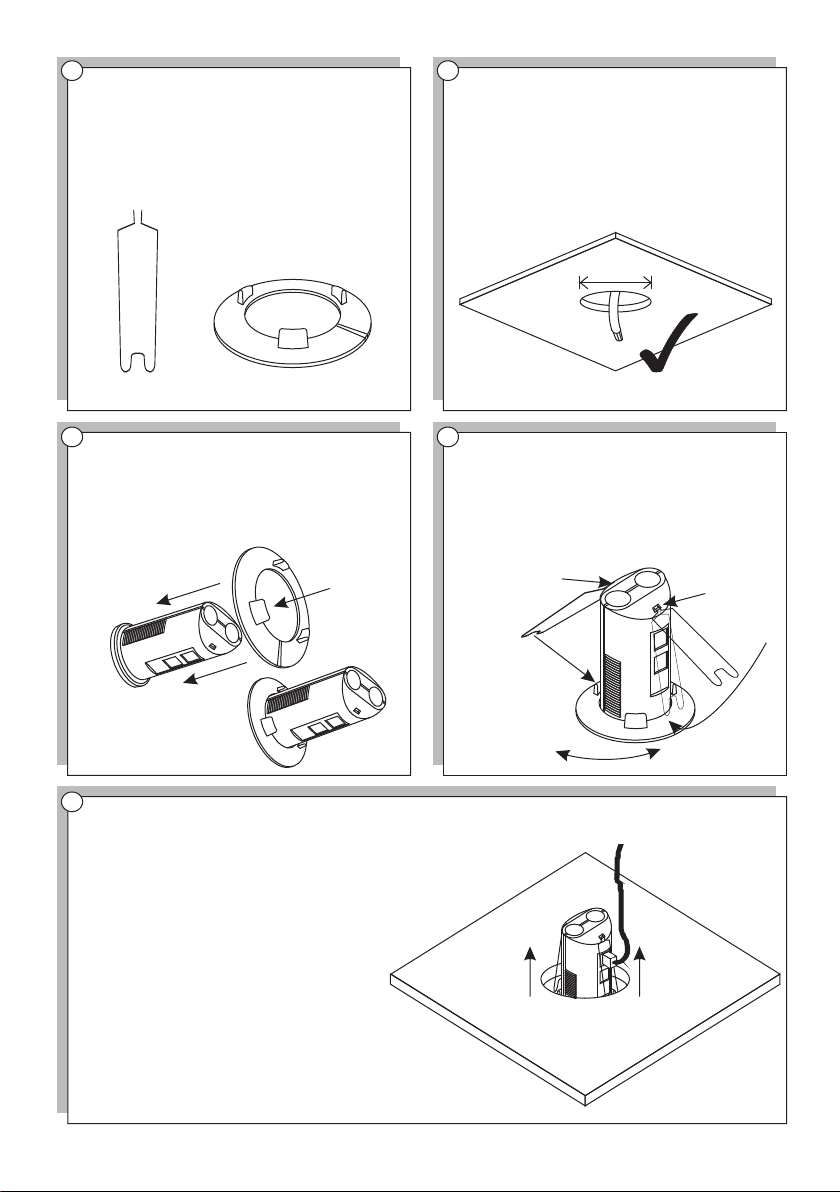
1 2
Supplied are 2 plasterboard fixing springs and
an FR64. A 64mm hole saw is also required.
The kit is for use only with Ex-Or’s range of
Slimline presence detectors.
Select a suitable mounting location and drill a
64mm hole into the plasterboard ceiling.
Ensure that any necessary first-fix wiring is
present before continuing.
X 2
3
Fit the FR64 to the Slimline presence detector
in accordance with its installation instructions.
Wire the de tector in accordance with its
installation instructions. If the detector is to be
connected via a patch lead (illustrated fig. 5,
below), the lead must not be fitted with strainrelief rubber boots.
(FR64)
5
Carefully bend the plasterboard fixing springs
down and hold the detector, FR64 and springs
(once bent into position), as one, from below.
Care must be taken not to release the springs
in this position as they are under pressure and
may detach from the detector. Feed the
detector and cable through the 64mm hole
until the assembly is flush with the ceiling.
Apply power to the detector and commission
as required.
Extra care must be taken if removing the
detector from the ceiling. The fixing springs are
held under pressure by the ceiling and may
detach from the detector upon its removal.
64.0mm
4
Insert the plasterboard fixing springs into the
two cut-outs at the rear of the detector. They
will be held in place by the plasterboard ceiling
once installed. Please note that in the drawing
below, spring ‘2’ will locate around the support
pillar on the FR64 when fitted in the ceiling.
The FR64 and fixing spring must be aligned
this way.
2
Check fixing spring
alignment.
View from above
plasterboard ceiling
1
Honeywell Ex-Or, Albery House, Springfield Road, Horsham, West Sussex RH12 2PQ
Tel: 01942 719229, Fax: 01942 508753 Email: technicalsales.ex-or@honeywell.com www.ex-or.com
 Loading...