

Page 1

Warning ............................................................. 2
Features ............................................................ 2
Important Safeguards ........................................ 2
Internal View ................................................... ...3
Mounting ............................................................ 4
Supply & Load Cable Connections .................... 5
Connecting Serial Control Cables...................... 6
Hardware Controls ............................................ 7
Dimmable Lamps Chart .................................... 7
Changing Scenes Using The Program Key ........8
Troubleshooting................................................. 9
Specification ..................................................... 9
Contents
Ex-Or
Haydock Lane, Haydock, Merseyside WA11 9UJ
Tel: 01942 719229 Fax: 01942 272767 Email: technicalsales.ex-or@honeywell.com
www.ex-or.com
W4386A
SMD810
Instruction Manual
MIXED DIMMER
SceneSelect II
Scene-setting and Dimming System
Page 2
ISOLATE FROM
MAINS SUPPLY BEFORE
REMOVING THIS COVER
NO USER SERVICEABLE PARTS INSIDE
SERVICE BY QUALIFIED PERSONNEL ONLY
WARNING
Warning
TO REDUCE THE RISK OF FIRE OR
ELECTRIC SHOCK, DO NOT EXPOSE
THIS DEVICE TO RAIN OR
MOISTURE.
DO NOT ENERGISE UNLESS THE
FRONT COVER IS IN PLACE.
THIS DEVICE MUST BE EARTHED.
INSTALLATION, PROGRAMMING AND
MAINTENANCE MUST BE CARRIED
OUT BY QUALIFIED PERSONNEL.
Simple Supply Requirement
230V 50Hz single phase at 40A.
4 Dimmed Outputs
Each dimmed 10A output is independently
regulated, protecting loads from voltage surges
and spikes. These outputs are overload
protected by individual 10A circuit breakers.
4 Switched Outputs
Each switched output is rated at 10A. These
outputs are overload protected by individual
10A circuit breakers.
4 Control Outputs
Each of the 4 optically isolated outputs can be
configured to be either 1-10V, DSI Serial control
or DALI broadcast, covering the latest types of
HF Fluorescent Ballasts. Also compatible with
1-10V, DSI and DALI dimmable electronic
transformers. These outputs can operate in
tandem or independently of the switched
outputs.
Convection Cooled
This device is convection cooled, requiring no
forced cooling system when installed in
accordance with these instructions.
Many Control Options
Control of this device can be from any of the
SceneSelect control panels and ancillary
products.
Simple Installation
Wall mount enclosure with mounting lugs
facilitates installation. A cable gland plate
is provided at the top of the enclosure for
supply and load cables and a knockout for
the low voltage (LV) control at the bottom.
Note:
Channel 1 (leading edge phase control) &
Channel 5 (switched output): Combined rating = 10A
Channel 2 & Channel 6: Combined rating = 10A
Channel 3 & Channel 7: Combined rating = 10A
Channel 4 & Channel 8: Combined rating = 10A
Features
SMD810 Instruction Manual - W4386A
2
Important Safeguards
Read Instructions We recommend that you read
this Instruction Manual prior to commencement of
installation. Retain these instructions and give the
end user the 'Changing Scenes Using the Program
Key' guide on page 8, if applicable.
Troubleshooting - If problems are encountered,
please check the troubleshooting section on page
9 before calling Ex-Or technical support.
Special Programming This device will only
operate in ‘basic’ mode unless programmed via a
computer. Should programming be required,
contact Ex-Or for details. Once the data cable is
connected to the device(s), the factory default
settings will allow any control panel to control all
channels in all dimmers.
Power Sources This device should only be
operated from the type of supply specified on the
front panel. This device must be earthed.
Output Circuits The load on a single circuit
should not exceed 10A for a dimmed channel and
10A for a switched channel. Loads should be
calculated to ensure that the total device load of
40A (10A per pair of channels: 1 & 5, 2 & 6, 3 & 7,
4 & 8) is not exceeded.
Load Control Circuits If this device is being
used to control 1-10V, DSI or DALI broadcast
HF Fluorescent Ballasts, a 2 core LV control
cable is required to be run to the loads, in
addition to the mains feed.
Load Type Default settings are for load control
outputs to be 1-10V. Check to see what type of HF
Fluorescent Ballasts are in the luminaires. Do not
terminate the control lines to any DSI or DALI loads
until the relevant channel has been programmed
as DSI or DALI. When connecting 1-10V load
control lines, pay attention that the correct polarity
is maintained.
Megger Testing Do not megger test any circuitry
connected to the dimming system, as damage to
the electronics may result.
Mounting Location This device must be mounted
the right way up, on a vertical surface (refer to page
4 for mounting instructions). The specified
minimum clearance of 200mm for all sides must be
adhered to. Install in a dry, well-ventilated location.
This device may emit some mechanical noise.
Take this into account when deciding the mounting
location.
Data Cable The recommended minimum grade of
cable for connections to the programming socket is
Category 5 FTP (screened). This cable should be
segregated from mains cables by a minimum
distance of 300mm. If expected cable runs are over
600 metres for bus cables or 12 metres for
analogue cables, consult Ex-Or for advice. Do not
cut or terminate live data cables.
Page 3
3
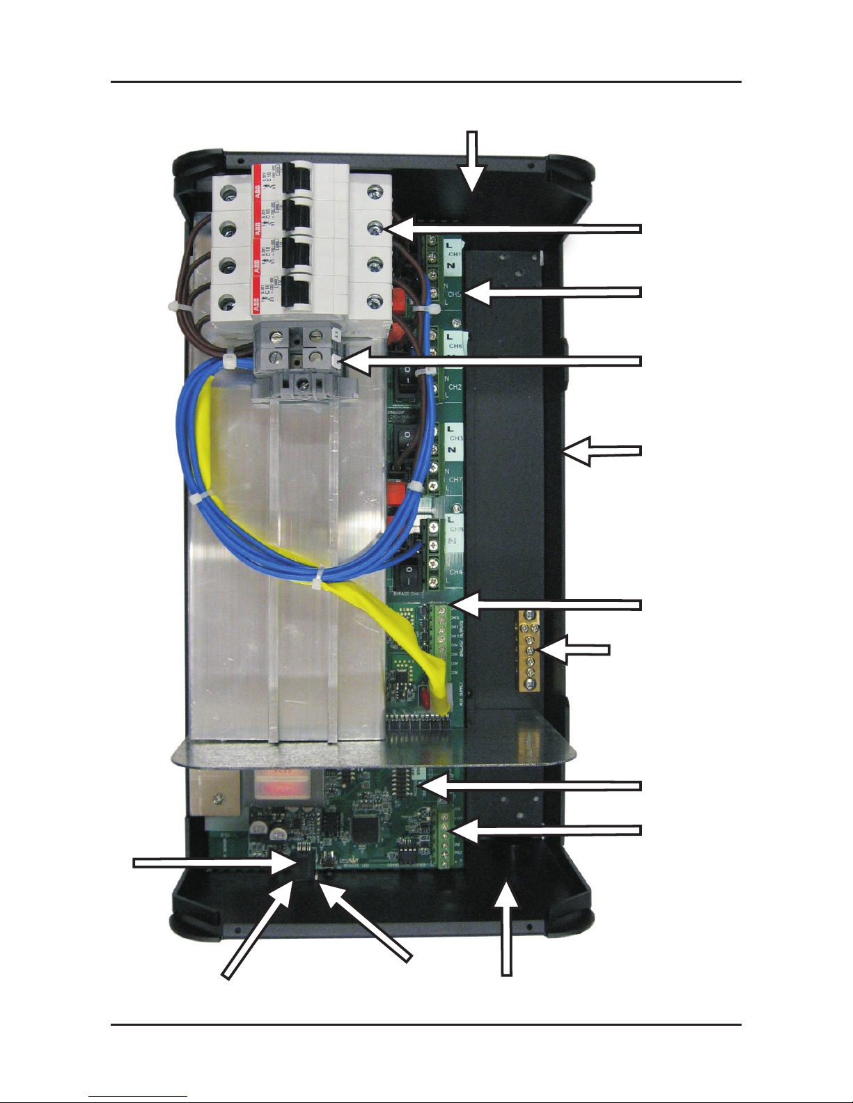
Internal View
SMD810 Instruction Manual - W4386A
Entry Gland Plate
for Load Cables
Circuit Breakers and
Emergency Lighting Line Outputs
Dimmed or
Switched 230V Outputs
40A Single Phase
Supply Connections
4 x Side Entry
Gland Knockouts
DALI Broadcast,
1-10V or DSI
Control Ouputs
Earth Link
Accessory Port
SceneSelect
Bus Terminations
Low Voltage
Cable Gland
Network
Socket
Service LED
Service Switch
Page 4

Mounting
4
SMD810 Instruction Manual - W4386A
DIMMER
CABLE TRAY OR
OTHER OBJECT
200mm MINIMUM GAP
200mm MINIMUM GAP
RISING HEAT
200mm MINIMUM GAP
200mm MINIMUM GAP
CABLE TRAY OR
OTHER OBJECT
SUPPLY CABLES
LV CONTROL CABLES
LESS THAN 200mm
Select a suitable location
This device is designed for indoor use only. If
installing in an external location, the device
must be housed in a suitable well-ventilated
enclosure. Choose a dry location, that will be
accessible after the installation is complete.
To ensure the cooling system functions
correctly, the device should only be mounted
vertically, the right way up. The device will
generate heat when operating, approximately
2 Watts per Amp of load, and requires an air
gap of 200mm on each side and at the top and
bottom of the device. This air gap is also
required to ensure serviceability of the device
without complete removal from the mounting
surface. This device may emit some
mechanical noise. Take this into account
when deciding the mounting location.
Fixing the Device
The device has integral mounting brackets
attached to the enclosure. The brackets are
designed to accommodate fixing screws up to
8mm diameter. The device can be fixed to the
wall without opening the cabinet or removing
the cover. Make sure no dust or other debris
enters the device during installation. Do not
leave the front cover off for any length of time.
Excessive dust and dirt can degrade the
cooling of internal components.
Allow For Cable Entry
Supply and Load cables should enter the
device at the top. If these cables are fed from
below the mounting position, they should be
routed around the device to enter at the top.
An alternative method is to stand the device off
from the mounting surface by mounting it on a
cable tray or a ‘Unistrut’ style product. The
cables can then be routed between the device
and the mounting surface, and enter the
device via the cutout provided on the mounting
face. The control cables enter at the bottom of
the device. Control cables should never be
run in the mains voltage sections of the device.
DIMMER
DIMMER
DIMMER
Page 5

Supply & Load Cable Connections
5
SMD810 Instruction Manual - W4386A
Supply Cables
The supply input terminals are located toward the
middle of the enclosure and consist of Earth, Neutral,
2
and Live, all of which will accept up to 10mm cables.
The supply cables should have a capacity of 40A to
allow the device to be loaded to its maximum capacity.
Load Cables
Load cables can be terminated on the 16-way load
terminal strip (one Live/Neutral pair for each channel)
and an Earth link located at the centre of the PCB.
2
These connectors will accept up to two 4mm cables. It
is important that an individual output circuit is not
overloaded. Calculate the intended load, and ensure
that it is below the maximum capacity of an individual
channel - Note that current for emergency lighting also
adds to the load at each breaker. Channels 1-4 are
dimmed channels with a maximum capacity of 10A per
channel. Channels 5-8 are switched channels, with a
maximum capacity of 10A per channel.
Note:
Channel 1 (leading edge phase control) & Channel 5
(switched output): Combined rating = 10A
Channel 2 & Channel 6: Combined rating = 10A
Channel 3 & Channel 7: Combined rating = 10A
Channel 4 & Channel 8: Combined rating = 10A
To ensure compliance with interference standards, the
load Neutral cables must be individually connected to
the neutral link terminals inside the cabinet. Never use
a common Neutral at a remote location.
Load Control Cables
Load Control cables can be terminated on the 8 way
terminal strips located directly below the Load
terminals. These terminals are labelled CH5 to CH8,
and can operate in tandem with the corresponding
Load Outputs, or can be programmed to operate
independently. 1-10V, DSI or DALI broadcast is
selected by reprogramming via computer. Install the
jumper for 1-10V operation (factory default). Note that
1-10V HF Fluorescent Ballast control wiring is polarity
conscious. DSI and DALI ballasts are not polarity
conscious.
Emergency Lighting Connections
Connect emergency lighting circuits to the load side on
the circuit breaker for the relevant channel, as
indicated by the labels next to the circuit breakers. Do
not remove any cables that may already be terminated
at this location.
Energising the Device
If it is necessary to energise load circuits before any
control cables are connected, it is acceptable to
replace the cover and power up the device
immediately, as the default factory programming is to
have all channels set to 100% output. If there is no
output on any or all channels, see the troubleshooting
section on page 9. This device should be powered
down before terminating the control and data cables.
Dimmed
Dimmed
Dimmed
Dimmed
Switched
Switched
Switched
Switched
2.
3.
1.
1.
4.
1. Supply Terminals
2. Emergency Lighting Terminals
3. Load Terminals
4. Ballast Control Terminals 1-10V,
DSI or DALI Broadcast
Page 6

Connecting Serial Control Cables
6
SMD810 Instruction Manual - W4386A
RJ12 Socket Connections
Connect Data Cable in a "Daisy Chain"
SceneSelect Bus Cable Connections
There is one bus port in the form of an RJ12
socket on the front panel. This is used for the
tem p o r a ry c o n n e cti o n o f a PC f o r
programming purposes. There are more
terminals on the main circuit board for
permanent connections. Use Category 5 FTP
(screened) cable as a minimum. It should be
segregated from mains cables by a minimum
distance of 300mm. Recommended cable
types include:
Belden 9503
RS Components 368-687
One pair is paralleled for GND, one pair
paralleled for +12V, and one pair used for
DATA+ and DATA -.
Recommended Cable Colour Coding
Green/White pair paralleled for GND
Orange/White pair paralleled for +12V
Blue/White pair Blue for DATA+
White for DATA-
The colour coding scheme used is not critical,
as long as the same scheme is used
throughout the installation.
The screen of the data cable must be
connected where there is a terminal
provided.
Bus Cable Connecting Method
All devices on the SceneSelect Bus should be
connected together via a 'daisy-chain'
arrangement. 'Spurs' or 'stubs' off the
SceneSelect Bus are not permitted. Devices
may be connected in any order ensuring that
the first and last devices on the system
terminate one SceneSelect Bus cable only see diagram, left. Should the cable run exceed
600 metres then SBE Bus Extenders should
be used.
SPARE
PLUS
DATA --
DATA +
GND
SPARE
Serial Cable Permanent Connections
INSTALLATION DETAILS
INPUT: 230 V 50-60Hz 10 A
OUTPUT: 1 x 230V 10A
MOUNT VERTICALLY
AGAINST WALL
ENSURE GOOD VENTILATION
FOLLOW INSTALLATION
INSTRUCTIONS
Unit 6-119/133 McEVOY St. Alexandria
NSW 2015 AUSTRALIA
Manufactured by:
ISOLATE FROM
MAINS SUPPLY BEFORE
REMOVING THIS COVER
NO USER SERVICEABLE PARTS INSIDE
SERVICE BY QUALIFIED PERSONNEL ONLY
WARNING
1 cable
2 cables
2 cables 2 cables
SceneSelect II
SceneSelect II
Page 7

SMD810 Instruction Manual - W4386A
AUX Input - This is a dry contact interface that is active low. The dry contact is connected between the AUX and
GND terminals on the SceneSelect bus connector strip. The function of the AUX input is programmable.
Ensure that the cable length between the dry contact and terminal strip is no longer than 2 metres.
Service LED - The Service LED has 3 signalling modes, which are useful for troubleshooting:
Blinking slowly (1Hz) = Normal Operation
Blinking fast (0.25Hz) = Network Activity Detected
On = Fault
Service Switch - The Service Switch has three functions:
1 push = Transmit Network ID
3 pushes = All Channels 100%
Push & hold for 4 sec = Reboot
7
Incandescent lamps are easily dimmed using all SceneSelect II dimmers. The
soft start and voltage limiting features will extend lamp life. Lamp life can be
further extended using the voltage limit adjustment.
Tungsten halogen and other transformer loads are easily dimmed using all
SceneSelect II dimmers. The soft start, cleanup and surge limiting features will
protect lamps against premature failure. Lamp life can be extended using the
voltage limit adjustment.
Can be dimmed to as low as 1% using a dimmable electronic ballast.
No de-rating is necessary with electronic ballasts. 1-10V, DSI and DALI
ballasts can be controlled.
Some types of 4 pin PL lamps can be successfully dimmed using dimmable
electronic ballasts.
Only argon filled neon lamps can be reliably dimmed. The power factor
capacitors need to be wired to the supply side of the dimmer. Cabling and
controllers should be de-rated by approx 60% to allow for reactive current. Any
open circuit monitoring on the neon transformer must be suitable for dimming.
Hardware Controls
Dimmable Lamps Chart
INCANDESCENT
LAMPS
TUNGSTEN HALOGEN
LAMPS
FLUORESCENT
LAMPS
COMPACT
FLUORESCENTS
NEON
Page 8

8
SMD810 Instruction Manual - W4386A
Changing Presets Using The Program Key
STEP 1:
Select Preset to be changed by pushing buttons 1–4. The button
LED will indicate current scene.
STEP 2:
Hold down the PROGRAM button for approximately five
seconds, and then release it. All scene buttons will be flashing.
STEP 3:
To increase or decrease the brightness of all channels at the
same time press the up, down or off button until the required
brightness is required. You can now go to STEP 6 if happy with
the new levels, or continue if individual channel adjustment is
required.
STEP 4:
To set the level of an individual channel, press 1–4. The button
LED will indicate which channel you have selected. When more
than 4 channels are to be set, press 1 twice for channel 5, press
2 twice to select channel 6, press 1 three times to get channel 9
etc. (each press of the button increases the active channel
number by 4).
STEP 5:
Press the up, down or off buttons until the lamps on the selected
channel reach the desired level. Select the next channel and
change in the same way.
STEP 6:
When all channels of the preset scene have been established,
press PROGRAM again and the levels will be stored to the
current preset. To program another preset, repeat steps 1 - 6.
NOTE
This method is applicable only to simple systems comprising of one dimming unit and one eight button
programming panel.
Page 9

SMD810 Instruction Manual - W4386A
9
Troubleshooting
Specification
SYMPTOM
Dimmer does not operate at all. No Service LED
activity. Power supply indicator LED on PCB not lit.
Power supply indicator LED lit, but no Service LED
activity.
Dimmer will not respond to control panel push
buttons.
Dimmer operates properly but circuit breakers keep
tripping.
Fluorescent lights won’t dim.
PROBABLE CAUSE
Incorrect connection of mains supply, or no power
available.
Supply voltage too low, short circuit on network.
Control PCB faulty.
Control panel incorrectly wired or incorrect
configuration.
Instant tripping:- short circuit on load.
Delayed tripping:- dimmer overloaded.
Wrong type of ballast or ballast incorrectly wired.
ACTION
Check power supply to dimmer. Check Line and
Neutral input connections.
Check supply voltage is at least 75% of rated
voltage. Check 5V & 12V terminal voltages, 5V
supply must be present. Disconnect network bus
and restore power. Replace control PCB.
Check operation of LEDs on control panel. Push
button on panel and study response of service LED.
Check load wiring for short circuits. Verify dimmer
loading with current tester (don’t forget to de-rate for
low power-factor loads and transformer losses).
Check that the breaker terminals are tight.
Check ballast type. Check actual wiring against
ballast manufacturer’s diagram. Check 1-10V/DSI
settings.
Check the following list. If you are still unable to rectify the situation, contact Ex-Or. Please ensure that you have completed the following
prior to calling our technical support department.
l
Check all symptomsin the Troubleshooting list
l
Check for anydeviations between the installationand the installationinstructions
l
Make a listof the modelnumbers of all devices used in thesystem
Supply: 230V, 50Hz single phase at 40A
Outputs: 4 x 10A dimmed (leading edge phase control) at 10A each
4 x 10A switched outputs
4 x HF ballast control outputs selectable to 1-10V DC, DSI or DALI broadcast
Protection: 4 x 10A 6kA single pole thermal magnetic circuit breakers
Regulating Device: Triac 600V, 40A nom. 400A surge
Switching Device: Relay 16A nom. up to 800A surge
Power Conditioning; Regulated outputs
Over voltage protection
Surge protection
Brownout/Sag protection
Spike protection
Soft Start
16 bit fade resolution (65535 steps)
Interference Suppression: Iron powder toroidal choke
Rise Time: 100µS at 230V
Control Inputs: 1 x SceneSelect bus serial port
1 x programmable dry contact AUX input
User Controls: Service Switch
Diagnostic LED
Override switch - All channels to 100%
Internal Controls: Programmable Logic Controller
SceneSelect Bus DC Supply: 200mA (supply for approximately 8 Control Panels)
Preset Scenes: 170
2
Supply Terminals: Live, Neutral 2 x 10mm max conductor size
Output Terminals: Live, Neutral for each channels 1-8
2
2 x 4mm max conductor size
Earth link bar provided
0V/DSI/DALI (broadcast) , +V/DSI for channels 9-12
2
1 x 2.5mm max conductor size
Cable Entries: Mains 8 x 25mm dia. knockout
Data 1 x 25mm dia. knockout
Compliance: CE, C-Tick
o
Ambient Temperature: 40 C max.
Construction: Alloy/Steel wall mount case with epoxy finish
Dimensions: Height 370mm x Width 215mm x Depth 170mm (excludes wall brackets)
Weight: 7.5 Kilograms (packed weight)
Page 10

Notes
 Loading...