

Page 1
LightSpot Luminaire Controllers
MSM2000D/DALI - Digital Control Module
DHW/DHS - Mini Detector Head
Installation and Commissioning
Instructions
Note: QuickSet Pro (or HP18*) required for commissioning
* Please note that the HP18 offers different/limited programming options
Page 2
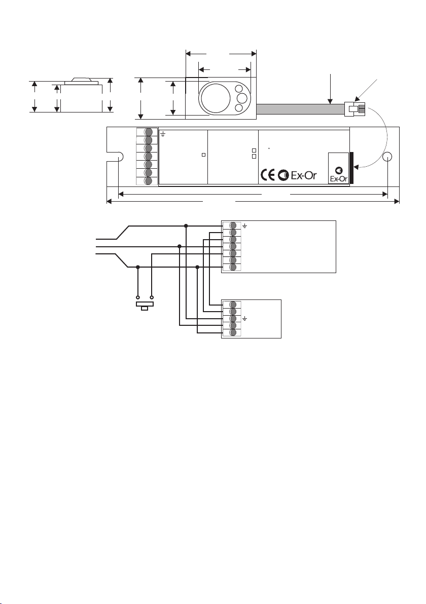
Electrical Connections
SIDE VIEW
18.8mm 17.5mm 21.3mm
Digital Control
Module
(Height = 21.3mm)
TOP VIEW
21.5mm
14.9mm
Polarity-free
}
Digital Output
Polarity-free
Neutral
}
Digital Output
OneSwitch Input
Neutral
N/C
Live
Live IN
32mm
21.5mm
0.5 - 1.5
0.5 - 1.5
Control Module Part No
Digital Control Module
Operating voltage 230V 50Hz 10%
MSM2000D
Control output: Digital
MSM2000DALI
Max 4 x DSI Ballast
Power consumption: <2W
tc 70 C
Read instructions prior to installation
Made in the EC
147.5mm
MSM2000D
Mini Detector
Head
Operating voltage 230V 50Hz 10%
Control output: Digital
MSM2000D
Max 4 x DSI or DALI Ballast
Power consumption: <2W
tc 70 C
+
-
Please read instructions
prior to installation
Made in the EC
135mm
800mm
Flying Lead
+
-
DHW/DHS
Detector
Connection
Connection
RJ12
Plug
Mains Supply
Polarity-free
}
Digital Output
Neutral
OneSwitch Input
N/C
Live IN
Digital Regulating Ballast(s)
Polarity-free
}
OneSwitch Input
for manual control
Digital Input
Neutral
Live IN
Mounting Details
The MSM2000 Control Module is designed to be mounted within the luminaire on fixing centres of 135mm.
Connections to the control module as shown above should be made using solid strand wire (0.5-1.5mm ).
2
The interconnect cable between the detector head and control module should be routed away from other
luminaire internal wiring and away from the lamp end-caps.
The recommended position for the detector is in the middle of the luminaire. Where this is not possible and the
detector is fitted near on end of the lamps, please ensure that the detector is at the ‘cold’ end of the lamps.
The DHW/S Mini Detector Head should be mounted such that only the raised front section of the bezel protrudes
through the cut out in the louvre or infill panel, constructed in accordance with the dimensions above.
Installation Guidelines
1. The Mini Detector Head must be mounted within the luminaire. Do not mount remotely.
2. The connecting cable must not be extended.
3. Artificial light illuminating the Mini Detector Head must only be reflected from the room - i.e. there must be no
direct illumination.
4. In order to receive satisfactory light-level regulating operation, a detector must observe a substantially greater
proportion of artificial light from the luminaire(s) under its control than from neighbouring luminaires not under its
control. This is particularly important when planning the installed layout of linear luminaires that have an integral
detector positioned at one end.
Page 3

Commissioning
Detectors are supplied factory pre-set which ensures the lighting will switch on automatically as soon as power
is applied. Final commissioning of the detectors requires the use of an infrared Programmer. The QuickSet Pro
gives access to the full range of parameters and options but limited programming functions can also be carried
out using an HP18.
Commissioning Detectors using the QuickSet Pro Programmer
It is important that the Programmer be held perpendicular between 0.5m and 2m from the sensor.
1. Switch on by pressing any button (and unlock with top left rectangular button).
2. Point the programmer at detector and press the DOWNLOAD button. The programmer will confirm the
product’s identity and call up the correct menu of parameters and their current settings.
3. Use a combination of UP, DOWN, FORWARD and BACK buttons to navigate the parameter menu,
selecting options for each shown.
4. When options for all parameters have been selected, point the programmer at the detector and press the
UPLOAD button. The luminaire(s) will switch off briefly during the programming process.
5. After a short period of inactivity (default 5 minutes), the programmer hibernates retaining the most recent
settings.
OneSwitch Dimming
OneSwitch dimming affords local control to the end-user whereby a simple, momentary, push-to-make wall
switch can be used to raise or lower the lighting level or to toggle the output ON/OFF. A press of less than
1 second will toggle the output status while a longer press will raise or lower the output. Each time the switch is
pressed, the direction of dimming reverses. If the switch has not been pressed for 5 seconds, the direction will
be up (brighter) - unless the output is already above 90% (dc 8V) in which case the direction is down.
To Test with Hand-held Controller
Once the LightSpot Luminaire Controllers have been installed within the luminaires, a Hand-held Controller or
Programmer (HC5A or HP18) may be used to dim and brighten luminaires and to switch them ON and OFF.
NB: See also ‘Important Additional Notes’ overleaf.
Page 4

Technical Data
MAXIMUM RECOMMENDED MOUNTING HEIGHT: 3.0m
RANGE: Cone-shaped detection pattern, diameter (at floor level) = 2.4 x mounting height
2.5m
6.0m
OPERATING VOLTAGE: 230V 50Hz (UK & Europe)
ta = 0 - 50 C
CAPACITY: Max 4 x DSI or DALI ballasts
INTERCONNECT CABLE TEMPERATURE RATING: 60 C
o
o
COLOUR: White (RAL9010) or silver bezel (DHW = White, DHS = Silver)
MATERIAL: UV stabilised polycarbonate (DHW/DHS)
Flame retardant PC/ABS (MSM2000D/DALI)
IP RATING: 20
DIMENSIONS: 32 (l) x 21 (w) x 18.6 (h) mm (DHW/DHS)
147 (l) x 30 (w) x 21 (h) mm (MSM2000D/DALI)
WEIGHT: 32g incl. 0.8m cable (DHW/DHS)
48g (MSM2000D/DALI)
Important Additional Notes
1. A means for disconnection must be incorporated in the fixed wiring in accordance with the current wiring regulations.
2. Although nominally 12V, the dimming output is not SELV and therefore should be treated with the same respect as mains
with regard to wiring practice. The 0V line of the dimming output is almost at Neutral potential.
3. The dimming control output should be connected only to the control input of the ballasts - never to other detectors.
4. This equipment should be used to control only those ballasts powered from the same phase as the detector.
5. Due to the fact that the photocell is on the ceiling looking down, it is not possible for measurements made with a lux meter on
the working plane to remain constant when daylight illuminates the ceiling and the working plane to a differing extent.
Therefore, products of this type should be regarded as capable of maintaining an APPROXIMATE light level only.
6. This equipment switches lights no more frequently than would a responsible human occupant. However, manufacturers of
some particular lighting types (e.g. ‘2D’ luminaires) may specify a maximum number of switching cycles in order to achieve a
predicted lamp life. Please check with the manufacturer of the luminaires to ensure that they are compatible with automatic
controls in this respect.
7. Some devices in this product range feature a silvered surface finish; this is intended for decorative purposes only. Care
should be taken to avoid accidental separation of the silvered coating from the product. If the unit is built into a luminaire
that is subsequently wrapped in film having adhesive properties, it is recommended that a layer of suitable packaging
material be used to protect the silvered area.
Honeywell Ex-Or
Albery House, Springfield Road,
Horsham, West Sussex RH12 2PQ
Tel: +44 (0)1942 719229
Fax: +44 (0)1942 508753
Email: technicalsales.ex-or@.com
www.ex-or.com
At the end of their useful life
the packaging and product
should be disposed of via a
suitable recycling centre.
Do not dispose of with normal
household waste.
Do not burn.
W4267H
 Loading...