

Page 1

IP65 BattenFit Sensor
MSB1001T - Switching
MSB1001PT - Switching with photocell
Installation and Commissioning
Instructions
Note: QuickSet Pro or HP18* required for commissioning
* Please note that the HP18 offers different/limited programming options
Page 2
IP65 BattenFit Sensor: MSB1001T - Switching
MSB1001PT - Switching with photocell
Only suitably qualified personnel should install this equipment.
This passive infrared presence detector is designed to be fitted to a batten-style luminaire.
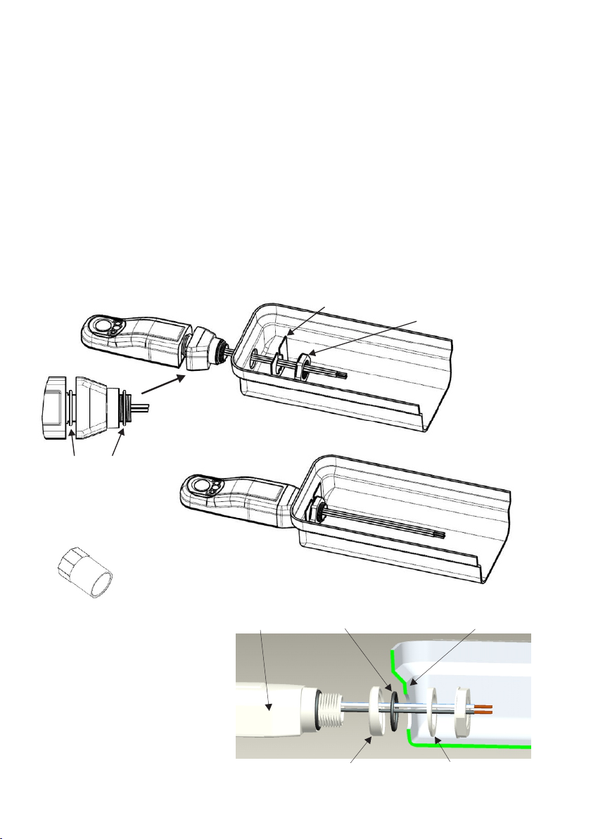
Installation
1. Remove the M20 knockout from the end cap of the luminaire.
2. Pass the sensor wires through from the outside and insert the threaded end of the sensor into the hole.
3. A polarising plate can be made in order to prevent rotation of the sensor - an example design is given on
page 3 (Fig.5).
4. If a polarising plate is to be used, pass the wires through the slot and position the polarising plate against
the inside face of the end cap. Ensure that the tab is positioned correctly i.e. at the ceiling side, away from
the lamp.
5. Fit and tighten the locknut.
6. Connect the wires in accordance with the wiring instructions.
OPTIONAL POLARISING PLATE
LOCKNUT
SENSOR
Fig. 1a
ENSURE THAT THE TWO O-RINGS
ARE FITTED AS SHOWN
If there is insufficient space for the locknut,
the adaptor shown below (Fig. 3) can be used.
20mm Female Adaptor
Fig. 3
Angled Washer Kit (supplied)
If the light fitting has an angled (drafted) end
face then use the kit provided as shown
(Fig. 4).
MK part number EFA/2
IP65 LIGHT FITTING
Fig. 2
IP65 SENSOR 20mm O-RING LUMINAIRE WITH ANGLED END FACE
Fig. 4
ANGLED SPACER ANGLED WASHER
Fig. 1
- 2 -
Page 3
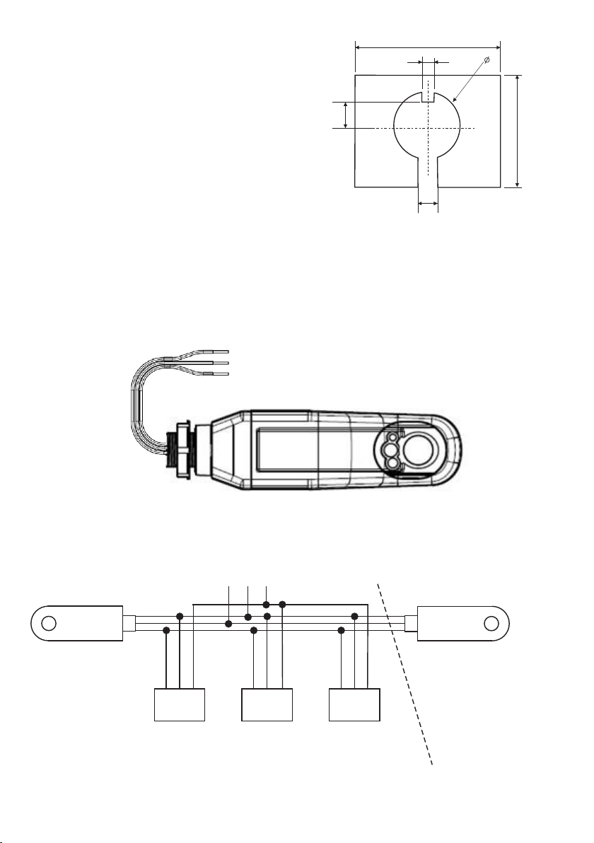
Polarising Plate (not supplied)
The purpose of the polarising plate is to ensure that the sensor does
not rotate from the correct position, i.e. pointing vertically
downwards, during transport or installation.
The two overall dimensions marked ‘SEE TEXT’ need to be made
such that when the plate is positioned against the inner face of the
luminaire end cap, it cannot rotate.
The 3.5mm ‘tab’ should be located closest to the ceiling (away from
the lamp). The 6.0mm slot is optional and is to allow the wires to
pass through for ease of assembly.
Material can be plastic sheet, minimum thicknesss 1.0mm,
recommended thickness 1.5-2.0mm, or mild/stainless steel sheet,
minimum thickness 0.6mm, recommended thickness 1.0-1.6mm.
Electrical Connections
Brown - Live
Blue
- Neutral
- Switched live
Black
SEE TEXT
3.5
7.3
6.0
20
SEE TEXT
Fig. 5
Fig. 6
Fig. 7
Blue
Brown
Black
SUPPLY
L N E
L N E
LOAD
L N E L N E
LOAD
Maximum Total Load not to exceed
that specified for a Single Detector
- 3 -
Always check product label before connecting.
Blue
Brown
Black
Multiple Detectors
may be connected
in parallel, as is
shown above, to
LOAD
control the same
Maximum Load
Page 4

Detection Profile
Plan View
Detection pattern is a 360 cone shape.
o
Diameter is 2.25 x the mounting height.
The squares show the arrangement
of the detection pattern.
Fig. 8
5m
Direction of most
commonly used
entry into detection
zone, i.e. start of
corridor or doorway
2.5m
o
97
DETECTION ZONE
5.6m
BATTEN LUMINAIRE
2.5m
5m
Fig. 9
- 4 -
Page 5

If the distance between the
bottom of the sensor and
the bottom of the end cap
exceeds 59mm (in the case
of square covers) or 82mm
(for rounded covers), there
may be a blind spot in the
detection zone.
Fig. 10
Walk Testing
In order to verify the installation, there is an inbuilt facility (Walk Test Mode) to temporarily reduce the time delay
to 10 seconds. A QuickSet Pro or HP18 Programmer is required to access this facility.
Using the HP18:
Press the ‘TEST’ button to enable walk test mode.
Move around the area that is being controlled, stopping for 10 seconds to allow the lights to switch off, before
moving and triggering the lights back on.
Re-programme the desired Off Delay once testing is complete (MSB1000PT only).
Using the QuickSet Pro:
Go to the Utilities menu, choose ‘LightSpot/MLS/LCM’ then ‘User Test’, place the cursor over ‘Walk Test’, point
the programmer at the detector and press OK.
Move around the area that is being controlled, stopping for 10 seconds to allow the lights to switch off, before
moving and triggering the lights back on.
After 5 minutes, the time-out will be restored to what it was before walk test was enabled.
Notes on Walk Testing:
l During walk test, after the lights have turned off, wait 5 seconds before moving again because the sensitivity
is deliberately reduced for a few seconds following switch off.
l Sensitivity is greater when approaching the circular footprint at a tangent rather than heading towards the
centre (see Fig. 8).
l Most luminaires take approximately 1 second to strike after presence has been detected.
l The detection pattern is cone-shaped which means that when standing at the very edge of the detection
footprint only a person’s feet will be visible (see Fig. 9).
- 5 -
Page 6

Photocell
The photocell (MSB1001PT only) can be programmed to operate in one of two ways: Active or Passive.
(Factory default setting is ‘Passive’.)
In all operating modes, the photocell can hold lights off as a vacant area becomes occupied, and if the light
level falls too low during the period of occupancy, the lights switch on. In ‘Passive Mode’ the lights do not
switch off whilst the area is occupied no matter how much light is measured. In ‘Active Mode’ the photocell is
able to switch the lights off whilst the area is occupied.
Setting the Photocell
1. If the lights are not already on, switch them on manually by pressing ‘Utilities / LightSpot/MLS/LCM / IR
Remote / Luminaire+ / OK’ [QuickSet Pro], or ‘On’ [HP18]. Fluorescent lights do not reach full output until up
to 15 minutes after being switched on, so ensure that the lights are fully warmed up before continuing. This
stage may be omitted if the intention is to operate the detector’s photocell in Passive Mode only [the detector
must have already been programmed to Passive Mode].
2. Wait until the time of day when the natural light level is at the point below which you would want the lights to
be on, and above which you would not want the lights to be on.
3. Start the internal self-programming mechanism by pressing ‘Utilities / LightSpot/MLS/LCM / Set Light Level /
OK’ [QuickSet Pro], or ‘Set’ [HP18]. The detector takes a measurement, adds a small amount and stores the
value in the Upper Threshold. Then it turns the lights off, makes another measurement and stores the value
in the Lower Threshold. The lights now switch on again to acknowledge a successful programming
operation.
The two switching thresholds have now been set, and the difference between them is equal to the contribution
made by the electric lighting; this is the perfect amount of hysteresis to ensure that the lights will not oscillate.
The thresholds may be read back and fine-tuned if necessary using the QuickSet Pro. Please note that the
values are non-specific units i.e. not lux.
Note: The light level perceived by the detector at the moment immediately prior to a Download operation
[QuickSet Pro only] is shown momentarily on the programmer’s screen following the Download; this is a useful
mechanism for troubleshooting.
Active Mode
Passive Mode
Upper Threshold
Lower Threshold
Occupancy
Natural
Light
Level
Fig. 11
Duration of
Off Delay
- 6 -
Lights ON = Lights OFF =
Note that when the natural light
level exceeds the ‘upper threshold’
value, the lights do not immediately
turn off. They will turn off only when
the upper threshold has been
exceeded for the duration of the
programmed Off Delay.
Area Occupied =
Area Unoccupied =
Page 7

Parameter Options - MSB1001PT only
Programming is carried out using an infrared programming tool. Please note that the full range of parameters is
accesible via the QuickSet Pro; the HP18 offers different/limited programming options.
Off Delay
The Off Delay may be set between 1 minute and 96 hours using the QuickSet Pro, or at 5, 10 or 20 minutes with
the HP18. A 10-second Off Delay is available for walk-testing the product. In a typical office environment, the
default 20-minute Off Delay is usually satisfactory.
Response (Automatic/Semi-Automatic)
Where absence detection is required (i.e. the user manually turns lights ON if required but lights still turn off
automatically once an area is vacated), semi-automatic operation can be set via the programmer.
Power Up Setting (On/Off)
Set to ON the detector will automatically switch its outputs on when Mains is applied. If set to OFF, the detector
will power up without turning its outputs on, wait for 30 seconds and THEN look for movement. Only if the area is
occupied will the output switch on at this time. The detector must be set to Power Up ON when used in
conjunction with semi-automatic operation.
Photocell Mode (Passive/Active/Disabled)
The MSB1000PT has an in-built photocell. The photocell has three modes of operation - Passive, Active and
Disabled. Its operational behaviour is governed by the setting chosen and by the values stored in the Upper and
Lower thresholds (see Fig. 11).
Passive - The photocell will inhibit turn-on of the controlled load if sufficient natural light is available. It will not turn
the load off whilst an area is occupied
Active - The photocell will turn the controlled load on and off as required whilst natural light levels fluctuate during
a period of occupancy. This mode of operation operates in conjunction with a passing cloud timer (PCT). The
PCT is asymmetrical in operation - the load will be switched on immediately that the light level falls below the
lower set point, however, the load switches off only if the light level exceeds the upper threshold continuously for
a period equal to the Off Delay.
Disabled - The photocell has no effect.
24 Hour Cycle (Yes/No)
Not applicable.
Defaults (Fixed on MSB1001T)
The units are supplied with factory default settings (Power-Up On, fully Automatic operation, a 20-minute Off
Delay, no 24 Hour Cycle, Passive Photocell).
- 7 -
Page 8

Dimensions
All dimensions in mm
Fig.12
M20 x 1.5
15
14
29
135580
Fig. 13
Fig. 12
40
Technical Data
MAXIMUM RECOMMENDED MOUNTING HEIGHT: 5 metres
OPERATING VOLTAGE: 230V~ 50Hz (UK & Europe)
POWER CONSUMPTION: <0.5W
CAPACITY: 2A Switching
MAXIMUM NUMBER OF BALLASTS: 4 (Electronic or HF Ballasts)
WEIGHT: 120g
COLOUR: White (RAL9010)
MATERIAL: Flame retardant PC
IP RATING: 65
Important Additional Notes
1. A means for disconnection must be incorporated in the fixed wiring in accordance with the current wiring regulations.
2. Due to the fact that the photocell (MSB1001PT) is on the ceiling looking down, it is not possible for measurements made
with a lux meter on the working plane to remain constant when daylight illuminates the ceiling and the working plane to a
differing extent. Therefore, products of this type should be regarded as capable of maintaining an APPROXIMATE light
level only.
3. This equipment switches lights no more frequently than would a responsible human occupant. However, manufacturers of
some particular lighting types (e.g. ‘2D’ luminaires) may specify a maximum number of switching cycles in order to achieve
a predicted lamp life. Please check with the manufacturer of the luminaires to ensure that they are compatible with
automatic controls in this respect.
Honeywell Ex-Or
Albery House, Springfield Road,
Horsham, West Sussex RH12 2PQ
Tel: +44 (0)1942 719229
Fax: +44 (0)1942 508753
Email: technicalsales.ex-or@.com
www.ex-or.com
At the end of their useful life
the packaging and product
should be disposed of via a
suitable recycling centre.
Do not dispose of with normal
household waste.
Do not burn.
W4483H
 Loading...