

Page 1

W4331B
Installation and Commissioning
Instructions
Ex-Or
Haydock Lane, Haydock, Merseyside WA11 9UJ
Tel: +44 (0)1942 719229
Fax: +44 (0)1942 272767
Email: technicalsales.ex-or@honeywell.com
www.ex-or.com
At the end of their useful life
the packaging and product
should be disposed of via a
suitable recycling centre.
Do not dispose of with normal
household waste.
Do not burn.
Technical Data
Nominal voltage: 220-240V, ~, +10%/-15%
Frequency: 50-60Hz
On/off switch delay: 0-20 min
Power consumption: ca. 3 VA
Contact material: AgSn0
2
Contact: phase-independent (zero-crossover switching)
Gap: <3mm (µ)
Switching capacity max: 16A, 250V~, cos j = 1
Switching capacity min: 10mA/230V AC
100mA/12V AC/DC
Switching capacity fluorescent lamps: 16 AX
Incandescent lamp load: 3600 W
Halogen lamp load: 3600 W
Fluorescent lamp loads - capacitive ballast:
uncorrected: 3600 VA
series corrected: 3600 VA
parallel corrected: 1200 VA (130µF)
dual circuit: 3600 VA
Fluorescent lamps - electronic ballast: 1200 VA
Mercury and sodium vapour lamps: series corrected: 1200 VA (130µF)
Compact fluorescent lamps - electronic ballast: 34x7 W, 27x11 W, 24 x 15 W, 22 x 23 W
o o
Permissible ambient temperature: -30 C ...+55 C (control unit)
o o
-40 C ... +70 C (sensor)
Protection class: II (light sensors III) for designated installation
Protection rating: IP20 (control unit), IP65 (sensor)
MP102 LightSpot Photocell
Page 2
W4331B
MP102 Two-part Photocell
Only suitably qualified personnel should assemble/install this equipment.
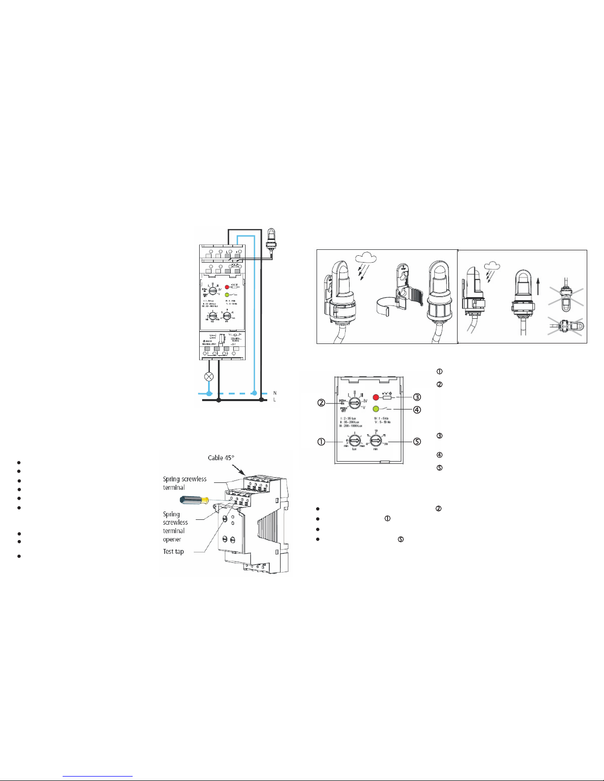
Potentiometer for setting the brightness threshold
Potentiometer for setting the brightness range:
and PERM ON/PERM OFF (test)
- I: 2-35 lx
- II: 35-200 lx
- III: 200-1,000 lx
- IV: 1,000-5,000 lx
- V: 5,000-50,000 lx
Immediate display of the switched condition by means of
a red LED
Display of channel condition by means of a green LED
Potentiometer for switch ON/switch OFF delay (0-20 min)
Connection/Assembly of light sensor
2 2
Note the length of the connecting cable: max 100m (2 x 1.5mm ), max 50m (2 x 0.75mm )
Avoid running the sensor line parallel to conductors.
Connection/Assembly
Danger of death through electric shock
Assembly may only be carried out by qualified electricians.
Disconnect power supply.
Ensure it is not turned on again.
Check power is off.
Earth and short-out.
Cover or shield any adjacent live parts.
Connect cable
Strip cable back to 8mm (max 9).
o
Insert cable in open terminal at 45 angle.
(2 cables per terminal position possible).
To open spring screwless terminal, press upwards
with screwdriver.
The MP102 is used for controlling the light facilities of streets,
external stairways, shop windows, entrances etc.
The device corresponds to EN 60669-2-1; it is designed for
installation on DIN top hat rails (in accordance with EN 50022).
The control unit is for use only in closed, dry rooms; the sensor is
intended for outdoor installation.
Display and control elements
*
*
Current connection required for smooth
zerocrossing switch operation
(see connection diagram)
Initial start-up
Set the desired range I-V on the potentiometer using a screwdriver.
Set the desired threshold .
The red LED will light up, if the set Lux value underruns the ambient brightness.
Recommendation: set a delay of at least 1 min, to avoid switching errors owing to lightening flashes, car
headlights etc.
 Loading...